EP1897831A2 - Procédé destiné au changement de rouleau dans un dispositif d'enroulement de rouleaux et dispositif d'enroulement de rouleaux pour l'enroulement d'une bande de matériau - Google Patents
Procédé destiné au changement de rouleau dans un dispositif d'enroulement de rouleaux et dispositif d'enroulement de rouleaux pour l'enroulement d'une bande de matériau Download PDFInfo
- Publication number
- EP1897831A2 EP1897831A2 EP07115501A EP07115501A EP1897831A2 EP 1897831 A2 EP1897831 A2 EP 1897831A2 EP 07115501 A EP07115501 A EP 07115501A EP 07115501 A EP07115501 A EP 07115501A EP 1897831 A2 EP1897831 A2 EP 1897831A2
- Authority
- EP
- European Patent Office
- Prior art keywords
- winding
- material web
- roll
- web
- separating
- Prior art date
- Legal status (The legal status is an assumption and is not a legal conclusion. Google has not performed a legal analysis and makes no representation as to the accuracy of the status listed.)
- Withdrawn
Links
Images


Classifications
-
- B—PERFORMING OPERATIONS; TRANSPORTING
- B65—CONVEYING; PACKING; STORING; HANDLING THIN OR FILAMENTARY MATERIAL
- B65H—HANDLING THIN OR FILAMENTARY MATERIAL, e.g. SHEETS, WEBS, CABLES
- B65H18/00—Winding webs
- B65H18/08—Web-winding mechanisms
- B65H18/14—Mechanisms in which power is applied to web roll, e.g. to effect continuous advancement of web
- B65H18/20—Mechanisms in which power is applied to web roll, e.g. to effect continuous advancement of web the web roll being supported on two parallel rollers at least one of which is driven
-
- B—PERFORMING OPERATIONS; TRANSPORTING
- B65—CONVEYING; PACKING; STORING; HANDLING THIN OR FILAMENTARY MATERIAL
- B65H—HANDLING THIN OR FILAMENTARY MATERIAL, e.g. SHEETS, WEBS, CABLES
- B65H19/00—Changing the web roll
- B65H19/22—Changing the web roll in winding mechanisms or in connection with winding operations
- B65H19/26—Cutting-off the web running to the wound web roll
-
- B—PERFORMING OPERATIONS; TRANSPORTING
- B65—CONVEYING; PACKING; STORING; HANDLING THIN OR FILAMENTARY MATERIAL
- B65H—HANDLING THIN OR FILAMENTARY MATERIAL, e.g. SHEETS, WEBS, CABLES
- B65H19/00—Changing the web roll
- B65H19/22—Changing the web roll in winding mechanisms or in connection with winding operations
- B65H19/28—Attaching the leading end of the web to the replacement web-roll core or spindle
- B65H19/286—Attaching the leading end of the web to the replacement web-roll core or spindle by applying adhesive to the web
-
- B—PERFORMING OPERATIONS; TRANSPORTING
- B65—CONVEYING; PACKING; STORING; HANDLING THIN OR FILAMENTARY MATERIAL
- B65H—HANDLING THIN OR FILAMENTARY MATERIAL, e.g. SHEETS, WEBS, CABLES
- B65H26/00—Warning or safety devices, e.g. automatic fault detectors, stop-motions, for web-advancing mechanisms
- B65H26/02—Warning or safety devices, e.g. automatic fault detectors, stop-motions, for web-advancing mechanisms responsive to presence of irregularities in running webs
- B65H26/025—Warning or safety devices, e.g. automatic fault detectors, stop-motions, for web-advancing mechanisms responsive to presence of irregularities in running webs responsive to web breakage
-
- B—PERFORMING OPERATIONS; TRANSPORTING
- B65—CONVEYING; PACKING; STORING; HANDLING THIN OR FILAMENTARY MATERIAL
- B65H—HANDLING THIN OR FILAMENTARY MATERIAL, e.g. SHEETS, WEBS, CABLES
- B65H2301/00—Handling processes for sheets or webs
- B65H2301/40—Type of handling process
- B65H2301/41—Winding, unwinding
- B65H2301/414—Winding
- B65H2301/4148—Winding slitting
Definitions
- the invention relates to a method for roll change in a roll winding device, in which at the end of a winding sequence wound with a web to a winding roll and stored in a winding bed formed by two axially parallel winding rollers winding sleeve is replaced with an empty winding tube, wherein the web over a the winding bed the end of the winding sequence, the material web is severed upon formation of a web tail and a material web start, the web end is then wound on the winding roll, then the winding roll is discharged from the winding bed formed by two axially parallel support rollers, thereafter the empty winding tube is introduced into the winding bed and then the web start and the attached web are wound onto the empty winding tube to form a winding roll.
- the invention relates to a roll winding device for winding a material web on at least one winding tube to at least one winding roll, which is mounted in a winding bed formed by a first and a second axially parallel support roller, wherein the material web runs over a winding bed remote from the partial peripheral surface of the first support roller and wherein an at least temporarily activatable release agent for web-wide severing of the material web in the region of the partial peripheral surface is provided when forming a material web end and a material web start.
- the roll winding device according to the invention is particularly suitable for carrying out the method according to the invention.
- a material web for example in the form of a paper or board web, is produced in a relatively large width of currently up to 12 m and virtually endless.
- the material web In order to be usable for a later consumer, for example a printing company, the material web must be subdivided into narrower webs, so-called material part webs. These narrower webs of material must then be wound into bobbins. For this purpose, a roll winder is used.
- the invention is also applicable to other webs, which also have to be wound into bobbins and handled in a similar manner, such as sheets of cardboard, plastic or metal foil, respectively.
- the support roller is usually provided with recesses open against its circumferential surface, so-called air discharge grooves. These recesses prevent, especially at high grammages, a safe separation of the web. For example, stay at grooved places like bars.
- the material web is held during its separation by means of negative pressure on the peripheral surface of the support roller to thereby reliably supply the material web start the winding tube set for the next roll set to be wound up.
- the negative pressure for the perforated over their entire roll shell away Carrier roller is produced with a vacuum fan.
- the achievable negative pressure is reduced such that grammages ⁇ 150 g / m 2 are no longer securely held.
- an excess of false air is caused by causing increased operating costs in the vacuum system.
- the use of a suction zone integrated in the carrier roll is also provided.
- the suction box forming the suction and arranged in the interior of the support roller suction box requires a complex supply and control / regulation system.
- various balancing measures have to be taken so that the reel winders can still be operated efficiently and safely even at higher machine speeds.
- the reel winder is delayed towards the end of the reel sequence from its machine speed.
- a counter-holder mounted during the winding sequence in a basic position is mechanically coupled to the first support roller, thus taken along by it and introduced between its part circumferential surface touched by the material web and the material web.
- a during the winding sequence stored in a basic position separating / bonding device is then applied over the material web on the anvil and at the same time, at least temporally overlapping or thereafter brought the roll winding device to a complete standstill, so that the anvil and the separating / bonding device in the Partial circumferential surface of the first support roller rest.
- the material web is severed by a release agent of the release / adhesive device during formation of a material web end and a material web start and applied both on the material web end and on the web start each at least one adhesive through the release / adhesive device.
- at least one web holder is also activated for the temporary retention of the material web beginning.
- the material web end provided with at least one adhesive is wound onto the winding roll when an end sheet bond is formed so that a finished winding roll is formed.
- the counter-holder is decoupled from the first support roller, preferably brought directly into its normal position and held during this Bring the web start of the release / adhesive device.
- the separating / gluing device is preferably brought directly into its basic position and held during this Bring the web beginning of the first support roller.
- the winding roller is discharged from the winding bed formed by the two paraxial support rollers and the empty winding tube is introduced into the winding bed. Subsequently, the material web start and the attached material web are wound in the formation of a Togethersblattverklebung on the empty winding tube to a winding roll. The winding sequence can now be continued again with the desired machine speed.
- the inventive method for roll change in a roll winder is characterized in particular by fast change times, since the Separation and the adhesive bonds of the two web web spaces can take place during the deceleration process.
- the inventive method is suitable for all types of material webs, including for material webs with higher grammages.
- the method according to the invention ensures a secure and optimal initial and final bonding of the two material web spaces.
- the release / adhesive device can also be used for the one splice after a tear in the material web.
- the roller winding device is preferably delayed to a speed in the range of 5 to 60 m / min, preferably from 8 to 30 m / min prior to the mechanical coupling of the preferably mounted about the first support roller counter-support with the first support roller.
- a speed range within this speed range, on the one hand, no damage is to be expected, on the other hand, it favors the desired fast changeover times.
- the first support roller, the web, the counterpart coupled to the first support roller and the entrained by the anvil separation / adhesive device are at least temporarily moved at the same speed.
- the same speeds also allow the achievement of increased process reliability.
- the material web is severed in a preferred embodiment by a displaceable in the direction of the center of the first support roller release agent, in particular cutting knife.
- the cutting blade in its working position web width or over the web width traversing effect.
- the at least one web holder for holding the material web start during its activation clamps the material web beginning or the attached material web with at least one further element, preferably one of the first support roller in the direction of the material web upstream roller. This reduces the complexity of clamping due to the use of an existing element with a reduced number of assemblies and parts with a reduced control effort.
- the at least one adhesive applied to the material web end as well as to the material web beginning by the release / adhesive device has an adhesive force which is greater on the two web web dimensions than on the release / adhesive device.
- the decoupled from the first support roller counter-holder can be brought in a first embodiment in a clockwise direction to its normal position. In a second embodiment, it can be brought counterclockwise after the application of the winding roll and before the introduction of the empty winding tube in its basic position. Both versions are characterized by their practical relevance, but the clockwise direction, taking into account temporal aspects, should be more advantageous.
- the material web beginning of the first support roller during the preferably direct Bring the release / adhesive device is held in its normal position preferably by an adhesive force or by a preferably controllable / controllable vacuum.
- the preferably controllable vacuum would be applied in a practical manner in the interior of the first support roller in the region of the material web beginning resting on the support roller.
- the final and initial reel bonding is preferably carried out during the reeling sequence prepared for the next roll change.
- the preparation may also provide for pivoting the separating / gluing device and equipping them with adhesives.
- the object of the invention is achieved in a roll winding device of the type mentioned in the first that during the winding sequence stored in a basic position counter-holder is provided so mechanically coupled to the end of a winding sequence with the first support roller, that it is taken from this and between their part of the web touched peripheral surface and the material web can be introduced.
- a mounted during the winding sequence in a basic position separating / bonding device is provided, which can be applied towards the end of a winding sequence on the web on the counter holder, the at least temporarily activatable release agent for web-wide severing of the web in the region of the partial peripheral surface in forming a material web end and Having a material web start and having at least one means for applying at least one adhesive to the material web end and the material web start.
- at least one web holder is provided for temporarily holding the material web start.
- the counter-holder pivotably mounted around the first support roller preferably has a U-shaped basic structure with two spaced bearing legs and an intermediate support part.
- the storage of the first support roller can also be used for storage of the counter-holder.
- the support part of the counter-holder preferably has a curved cross-sectional shape, wherein the inner radius of the curvature substantially corresponds to the radius of the first support roller.
- the mounting part has a groove, which is preferably mounted centrally in the cross-sectional shape, which allows the at least partially activatable release agent of the separating / adhesive device to be received.
- the separating / gluing device mounted so as to be pivotable about the first supporting roller preferably also has a U-shaped basic structure with two spaced bearing legs and a base part lying therebetween.
- the storage of the first support roller can be used in addition to the storage of the counter-holder for storage of the separating / bonding device.
- the base part of the separating / bonding device preferably has a curved cross-sectional shape, wherein the inner radius of the curvature substantially corresponds to the outer radius of the holding part of the counter-holder.
- the base preferably comprises at least three regions arranged in the direction of travel of the material web, wherein the first region has the means for applying at least one adhesive to the material web end, the second region following in the direction of travel of the web, the at least temporarily activatable release agent for web-wide severing of the material web in the region the partial circumferential surface has the formation of a material web end and a material web start and the third region following in the running direction of the material web has the means for applying at least one adhesive to the material web start.
- This arrangement of the three necessary areas claimed a minimum possible space for a given functionality of the separating / gluing device.
- the at least temporarily activatable release agent for web-wide severing of the material web is preferably a web-width or a cross-over the web width traversierende severing blade.
- a cutting knife is low in the acquisition and operating costs and constantly ensures the required cutting quality of the release agent.
- the separating / gluing device is preferably mechanically coupled with the counter-holder so that it is taken away from this at least temporarily. This allows a reduced number of assemblies and parts with a reduced control effort for the reel winder.
- the separating / gluing device is preferably pivotally mounted in its basic position.
- it can already be fitted with adhesives during the winding sequence.
- the at least one web holder for holding the material web start in a favorable embodiment is designed and arranged such that it during its activation the web start or the attached web with at least one further element, preferably one of the first support roller in the running direction of the web upstream roller clamps. This reduces due to the use of an existing element, the complexity of the clamping with a reduced number of assemblies and parts with a reduced control effort.
- a preferably controllable / controllable vacuum can be applied at least temporarily in the interior of the first support roller in the area of the material web beginning resting thereon.
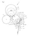
- the roll winding device 1 accordingly has a first axially parallel support roll 3 and a second axially parallel support roll 4, which form a winding bed 5 between them, in which an indicated winding roll 6 is arranged.
- the indicated winding roller 6 is shown here with diameters of different sizes in order to make the progress, ie the diameter increase, visible during winding.
- the material web 2 passes over a winding bed 5 facing away from the partial peripheral surface 7 of the first support roller 3 and is then wound onto the winding tube 16 to a winding roller 6.
- This type of web guide is referred to in professional circles as "upper web guide”.
- the partial circumferential surface 7 of the first support roller 3 is by definition the surface H which is formed between the contact point A of the material web 2 on the first support roller 3 and the discharge point B of the material web 2 from the first support roller 3 and the corresponding width of the material web 2.
- a supply station from which the material web 2 is withdrawn.
- This element is known per se in a roll winder.
- a plurality of winding rolls 6 can be arranged axially one behind the other in the winding bed 5 in the axial direction of the two support rolls 3, 4.
- the individual bobbins 6 are expediently distributed on both sides of the corresponding roller.
- such a roll winding device 1 is also provided with a longitudinal cutting device which divides the tapered material web 2 into a plurality of partial webs running parallel to one another.
- the partial webs may have a width in the range of about 0.3 to 4.8 m.
- a reel winder such as a back-up roll, also referred to as a rider or load roll, or drive motors for the support rolls 3, 4 are not shown.
- counter-holder 8 On the reel winder 1 a during the winding sequence in a basic position C1 (arrow) mounted counter-holder 8 is provided at the end of a winding sequence with the first support roller 3 mechanically coupled so that it is taken from this and touched between her from the web 2 Partial peripheral surface 7 and the material web 2 can be introduced.
- the counter-holder 8 can also be driven separately, in which case it would of course have to be electrically synchronized with the carrier roller 3 in a known manner.
- mounted separation / adhesive device 9 is provided on the reel winding device 1 during the winding sequence in a basic position D1 (arrow) mounted separation / adhesive device 9 . It is applied to the counter-holder 8 at the end of a winding sequence over the material web 2 and has an at least temporarily activatable release agent 10 for web-wide severing of the material web 2 in the region of the partial peripheral surface 7 of the first carrier roll 3 with formation of a material web end 2.E and a material web start 2 .A on (see Figure 3). Furthermore, it has at least one respective means 11.E, 11.A for applying at least one adhesive 12.E, 12.A to the material web end 2.E and the material web beginning 2.A (see again FIG.
- At least one web holder 13 is provided for the temporary support of the material web start 2.A on the reel winding device 1.
- the movable web holder 13 is arranged such that it during its activation the web start 2.A or the attached web 2 with at least one further element 14, preferably one of the first support roller 3 in the direction L (arrow) of the web 2 upstream roller 15 clamps .
- the web holder 13 may be formed, for example, as an illustrated roller 13.1 for linear clamping or as an unillustrated element with a flat surface for planar clamping.
- the roller 15 may also be the support roller 3 itself, so that a separate "upstream roller 15" could be dispensed with in the simplest version.
- FIG. 1 moreover shows the first stage of the method according to the invention for roll change in a roll winding device 1.
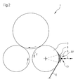
- the reel winding apparatus 1 is delayed towards the end of the winding sequence to a speed v (arrow) in the range of 5 to 60 m / min, preferably from 8 to 30 m / min. Thereafter, during the winding sequence in the basic position C1 (arrow) mounted counter-holder 8 is mechanically coupled to the first support roller 3, taken from this and consequently between their touched by the material web 2 peripheral surface 7 and the material web 2 is introduced (see Figure 2).
- FIG. 2 shows the next stage of the method according to the invention for roll change in a roll winding device 1.
- the basic position D1 (arrow) of the separating / gluing device 9 can be, for example, in the horizontal Z (double arrow).
- the first support roller 3, the material web 2, the counter support 8 coupled to the first support roller 3 and the separating / gluing device 9 entrained by the counter support 8 are moved at least at the same speed v (arrow) (see FIG.
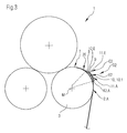
- FIG. 3 shows the third stage of the method according to the invention for roll change in a roll winding device 1.
- the roll winding device 1 is now brought to a standstill such that the counter-holder 8 and the separating / gluing device 9 rest in the region of the partial circumferential surface 7 of the first carrier roll 3.
- This rest position represents the working position C2 (arrow) for the counter-holder 8 and the working position D2 (arrow) for the separating / gluing device 9.
- the material web 2 is severed by the at least temporarily activatable release agent 10 of the release / adhesive device 9 in forming the material web end 2.E and the web start 2.A.
- the release agent 10 is displaceable out of a basic position E1 (arrow) (see FIG. 2) out in the direction of the midpoint M of the first carrier roller 3 into a working position E2 (arrow).
- the release agent 10 in the illustration is designed as a web-width or over the web width traversierende severing blade 10.1.
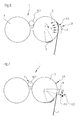
- FIG. 4 shows the following stage of the method according to the invention for roll change in a roll winding device 1.
- the web holder 13 Before, during or after the severing of the material web 2, the web holder 13 is activated for the temporary holding of the material web beginning 2.A. It is moved from a basic position F1 (arrow) (see Figure 1) out in a working position F2 (arrow) so that it the web start 2.A or the attached web 2 with the first support roller 3 in the direction L (arrow ) of the web 2 upstream roller 15 lines clamped.
- FIG. 5 shows the fifth stage of the method according to the invention for roll change in a roll winding device 1.
- the counter-holder 8 is decoupled from the first support roller 3 and preferably brought directly in a clockwise direction to its basic position C1 (arrow) (movement arrow J).
- the counter-holder 8 decoupled from the first support roller 3 can also be moved counterclockwise into its basic position C1 (arrow) after the application of the winding roller 6 from the winding bed 5 (see FIG. 1) and before the empty winding tube 16.1 (see FIG ) (dashed movement arrow K).
- FIG. 6 shows the following stage of the method according to the invention for roll change in a roll winding device 1.
- the separating / gluing device 9 is preferably brought directly into its basic position D1 (arrow) (movement arrow N), and during this bringing the material web beginning 2.A is held by the first support roller 3.
- the material web start 2.A is held by the first support roller 3 by a preferably controllable / controlled vacuum V, which is applied in the interior of the first support roller 3 in the region of the resting on the support roller 3 web start 2.A.
- the material web beginning 2.A can also be held by an adhesive force.
- the winding roller 6 (see Figure 1) from the winding axis 5 formed by the two axially parallel support rollers 3, 4 deployed and the empty winding tube 16.1 in the Winding bed 5 introduced.
- the application of the winding roll 6 takes place in a manner known to those skilled in the art, so that the corresponding device parts for the sake of clarity, are not explicitly shown.
- FIG. 7 shows the seventh process stage of the method according to the invention for roll change in a roll winding device 1.
- the material web beginning 2.A and the attached material web 2 are wound into a winding roller 6 in the formation of a Wegverklebung on the empty winding tube 16.1.
- the winding sequence of the reel winding device 1 can now be continued again with the desired machine speed.
- the final and initial sheet bonding can be prepared for the next roll change.
- the preparation can also provide pivoting (movement arrow G) of the separating / gluing device 9 and equipping it with adhesives 12.E, 12.A.
- the counter-holder 8 of the roll winding device 1 shown in FIG. 1 has a U-shaped basic structure 17 with two spaced bearing legs 18.1, 18.2 and an intermediate holding part 19.
- the holding part 19 has a curved cross-sectional shape Q.19, the inner radius R.20 of the Curvature 20 substantially corresponds to the radius R.3 of the first support roller 3.
- the holding part 19 has a groove 21 which is preferably mounted centrally in the cross-sectional shape Q.19 and which permits the at least temporarily activatable separating means 10 of the separating / gluing device 9 to be accommodated (see FIG.
- the separating / gluing device 9 of the roll winding device 1 shown in FIG. 1 has a U-shaped basic structure 22 with two spaced bearing legs 23.1, 23.2 and a base part 24 therebetween.
- the base part 24 again has a curved cross-sectional shape Q.24 the inner radius R.25 of the curvature 25 substantially corresponds to the outer radius R.19 of the holding part 19 of the counter-holder 8.
- the base 24 includes at least three in the direction L (arrow) of the web 2 arranged areas I, II, III.
- the first area I has the means 11.E for applying at least one adhesive 12.E to the material web end 2.E.
- the third region III following in the running direction L (arrow) of the material web 2 has the means 11.A for applying at least one adhesive 12.A1 to the material web beginning 2.A.
- the separating / bonding device 9 with the counter-holder 8 is mechanically coupled, that it is taken away from this at least temporarily.
- the invention provides both a method and a reel winder of the aforementioned types, with which a process improved, in particular temporally shortened separation of a web, in particular a web with a high grammage can be done.
Landscapes
- Replacement Of Web Rolls (AREA)
Applications Claiming Priority (1)
| Application Number | Priority Date | Filing Date | Title |
|---|---|---|---|
| DE200610042278 DE102006042278A1 (de) | 2006-09-08 | 2006-09-08 | Verfahren zum Rollenwechsel in einer Rollenwickeleinrichtung und Rollenwickelvorrichtung zur Aufwicklung einer Materialbahn |
Publications (2)
| Publication Number | Publication Date |
|---|---|
| EP1897831A2 true EP1897831A2 (fr) | 2008-03-12 |
| EP1897831A3 EP1897831A3 (fr) | 2009-07-01 |
Family
ID=38754759
Family Applications (1)
| Application Number | Title | Priority Date | Filing Date |
|---|---|---|---|
| EP07115501A Withdrawn EP1897831A3 (fr) | 2006-09-08 | 2007-09-03 | Procédé destiné au changement de rouleau dans un dispositif d'enroulement de rouleaux et dispositif d'enroulement de rouleaux pour l'enroulement d'une bande de matériau |
Country Status (2)
| Country | Link |
|---|---|
| EP (1) | EP1897831A3 (fr) |
| DE (1) | DE102006042278A1 (fr) |
Cited By (2)
| Publication number | Priority date | Publication date | Assignee | Title |
|---|---|---|---|---|
| WO2009126407A1 (fr) * | 2008-04-08 | 2009-10-15 | New Era Converting Machinery, Inc. | Enrouleur de transfert à extrémité libre |
| CN102544593A (zh) * | 2012-02-16 | 2012-07-04 | 深圳市赢合科技股份有限公司 | 一种自动换卷料装置 |
Family Cites Families (4)
| Publication number | Priority date | Publication date | Assignee | Title |
|---|---|---|---|---|
| AT373220B (de) * | 1979-07-27 | 1983-12-27 | Voith Gmbh J M | Doppeltragwalzenroller zum aufwickeln von materialbahnen |
| FI75788C (fi) * | 1985-11-28 | 1988-08-08 | Valmet Paper Machinery Inc | Foerfarande och anordning foer rullning av materialbana. |
| DE59309354D1 (de) * | 1993-08-24 | 1999-03-11 | Beloit Technologies Inc | Wickelmaschine zum Wickeln von Bahnen |
| DE19901112B4 (de) * | 1999-01-14 | 2004-04-01 | Voith Paper Patent Gmbh | Rollenwickelvorrichtung |
-
2006
- 2006-09-08 DE DE200610042278 patent/DE102006042278A1/de not_active Withdrawn
-
2007
- 2007-09-03 EP EP07115501A patent/EP1897831A3/fr not_active Withdrawn
Cited By (2)
| Publication number | Priority date | Publication date | Assignee | Title |
|---|---|---|---|---|
| WO2009126407A1 (fr) * | 2008-04-08 | 2009-10-15 | New Era Converting Machinery, Inc. | Enrouleur de transfert à extrémité libre |
| CN102544593A (zh) * | 2012-02-16 | 2012-07-04 | 深圳市赢合科技股份有限公司 | 一种自动换卷料装置 |
Also Published As
| Publication number | Publication date |
|---|---|
| EP1897831A3 (fr) | 2009-07-01 |
| DE102006042278A1 (de) | 2008-03-27 |
Similar Documents
| Publication | Publication Date | Title |
|---|---|---|
| DE60310943T2 (de) | Umwickelmaschine zur produktion von breitrollengewickelten bahnmaterials und dazugehöriges verfahren | |
| DE69507490T2 (de) | Verfahren und vorrichtung zum aufwickeln einer laufenden bahn in eine bahnrolle | |
| DE4003504A1 (de) | Verfahren und vorrichtung zum automatischen wechseln einer vollen wickelrolle gegen eine neue wickelhuelse | |
| EP0478719A1 (fr) | Procede et dispositif pour l'enroulement de bandes de materiau, en particulier les bandes de papier ou de carton. | |
| DE19710282A1 (de) | Wickelmaschine zum Aufwickeln einer Materialbahn | |
| DE4436719A1 (de) | Spleißer für bobinenartig aufgewickelte Verpackungsmaterialbahnen | |
| DE19808041A1 (de) | Verfahren zum Überleiten einer Materialbahn von einer Wickelrolle zu einer Wickelhülse und Wickelvorrichtung | |
| EP1798172B1 (fr) | Dispositif et méthode pour le déroulement d'une bande de matériau | |
| EP0963909B1 (fr) | Procédé et dispositif pour fabriquer un rouleau de matériau en bande emballée circonférenciellement, et un rouleau de matériau en bande | |
| DE4222880C2 (de) | Splicevorrichtung | |
| DE102008000475A1 (de) | Verfahren zum Aufwickeln einer laufenden Materialbahn sowie Wickelmaschine zur Durchführung des Verfahrens | |
| DE10139563B4 (de) | Vorrichtung und Verfahren zur Vorbereitung einer Vorratspapierbahnrolle für den fliegenden Rollenwechsel | |
| DE19734830C2 (de) | Wickelvorrichtung, insbesondere in einem Rollenschneider | |
| DE102006042217B4 (de) | In einem Rollenwechsler für eine Rollendruckmaschine durchgeführtes Verfahren zum Verbinden einer ersten Materialbahn mit einer zweiten Materialbahn | |
| DE102006042278A1 (de) | Verfahren zum Rollenwechsel in einer Rollenwickeleinrichtung und Rollenwickelvorrichtung zur Aufwicklung einer Materialbahn | |
| EP2082982B1 (fr) | Dispositif d'enroulement | |
| EP0438674A2 (fr) | Procédé à enrouler simultanément plusieurs bandes métalliques refendues | |
| EP2113479B1 (fr) | Procédé de transfert d'une bande de matériau déroulante et machine d'enroulement destinée à l'exécution du procédé | |
| EP0886620B1 (fr) | Dispositif d'enroulement continu de bandes de papier coupees longitudinalement avec changement automatique des rouleaux a vitesse de la machine | |
| DE60124366T2 (de) | Umfangsangetriebene Wickelmaschine und Verfahren zur Produktion von Rollen aus Bahnmaterial | |
| EP0957054A1 (fr) | Machine et procédé pour l'enroulement d'une bande de matière | |
| AT501666B1 (de) | Verfahren und wickelmaschine zum aufwickeln einer laufenden materialbahn | |
| EP1493699B1 (fr) | Procédé pour alimenter une bande, notamment une bande de papier ou de carton dans un dispositif pour enrouler des bandes et dispositif pour enrouler des bandes | |
| EP1652803B1 (fr) | Procédé d'enroulement | |
| EP2149528A2 (fr) | Dispositif d'enroulement, notamment dispositif d'enroulement de cylindres d'appui |
Legal Events
| Date | Code | Title | Description |
|---|---|---|---|
| PUAI | Public reference made under article 153(3) epc to a published international application that has entered the european phase |
Free format text: ORIGINAL CODE: 0009012 |
|
| AK | Designated contracting states |
Kind code of ref document: A2 Designated state(s): AT BE BG CH CY CZ DE DK EE ES FI FR GB GR HU IE IS IT LI LT LU LV MC MT NL PL PT RO SE SI SK TR |
|
| AX | Request for extension of the european patent |
Extension state: AL BA HR MK YU |
|
| PUAL | Search report despatched |
Free format text: ORIGINAL CODE: 0009013 |
|
| AK | Designated contracting states |
Kind code of ref document: A3 Designated state(s): AT BE BG CH CY CZ DE DK EE ES FI FR GB GR HU IE IS IT LI LT LU LV MC MT NL PL PT RO SE SI SK TR |
|
| AX | Request for extension of the european patent |
Extension state: AL BA HR MK RS |
|
| RIC1 | Information provided on ipc code assigned before grant |
Ipc: B65H 26/02 20060101ALI20090527BHEP Ipc: B65H 19/26 20060101ALI20090527BHEP Ipc: B65H 19/28 20060101AFI20071211BHEP |
|
| 17P | Request for examination filed |
Effective date: 20100104 |
|
| AKX | Designation fees paid |
Designated state(s): AT DE FI IT SE |
|
| GRAP | Despatch of communication of intention to grant a patent |
Free format text: ORIGINAL CODE: EPIDOSNIGR1 |
|
| RTI1 | Title (correction) |
Free format text: METHOD FOR REPLACING THE ROLL IN A ROLL WINDING DEVICE AND ROLL WINDING DEVICE FOR WINDING A WEB MATERIAL |
|
| STAA | Information on the status of an ep patent application or granted ep patent |
Free format text: STATUS: THE APPLICATION IS DEEMED TO BE WITHDRAWN |
|
| 18D | Application deemed to be withdrawn |
Effective date: 20110902 |