EP1898005A2 - Elément de gabion pour le montage de murs de soutènement ou analogues - Google Patents
Elément de gabion pour le montage de murs de soutènement ou analogues Download PDFInfo
- Publication number
- EP1898005A2 EP1898005A2 EP07017403A EP07017403A EP1898005A2 EP 1898005 A2 EP1898005 A2 EP 1898005A2 EP 07017403 A EP07017403 A EP 07017403A EP 07017403 A EP07017403 A EP 07017403A EP 1898005 A2 EP1898005 A2 EP 1898005A2
- Authority
- EP
- European Patent Office
- Prior art keywords
- wall part
- stone basket
- element according
- basket element
- retaining wall
- Prior art date
- Legal status (The legal status is an assumption and is not a legal conclusion. Google has not performed a legal analysis and makes no representation as to the accuracy of the status listed.)
- Granted
Links
- 239000004575 stone Substances 0.000 claims 33
- 230000003014 reinforcing effect Effects 0.000 claims 6
- 239000000463 material Substances 0.000 claims 5
- 230000001154 acute effect Effects 0.000 claims 1
- 238000004519 manufacturing process Methods 0.000 abstract 1
- 239000011435 rock Substances 0.000 abstract 1
Images

Classifications
-
- E—FIXED CONSTRUCTIONS
- E02—HYDRAULIC ENGINEERING; FOUNDATIONS; SOIL SHIFTING
- E02D—FOUNDATIONS; EXCAVATIONS; EMBANKMENTS; UNDERGROUND OR UNDERWATER STRUCTURES
- E02D29/00—Independent underground or underwater structures; Retaining walls
- E02D29/02—Retaining or protecting walls
- E02D29/0208—Gabions
-
- E—FIXED CONSTRUCTIONS
- E01—CONSTRUCTION OF ROADS, RAILWAYS, OR BRIDGES
- E01F—ADDITIONAL WORK, SUCH AS EQUIPPING ROADS OR THE CONSTRUCTION OF PLATFORMS, HELICOPTER LANDING STAGES, SIGNS, SNOW FENCES, OR THE LIKE
- E01F8/00—Arrangements for absorbing or reflecting air-transmitted noise from road or railway traffic
- E01F8/02—Arrangements for absorbing or reflecting air-transmitted noise from road or railway traffic specially adapted for sustaining vegetation or for accommodating plants ; Embankment-type or crib-type noise barriers; Retaining walls specially adapted to absorb or reflect noise
- E01F8/021—Arrangements for absorbing or reflecting air-transmitted noise from road or railway traffic specially adapted for sustaining vegetation or for accommodating plants ; Embankment-type or crib-type noise barriers; Retaining walls specially adapted to absorb or reflect noise with integral support structure
- E01F8/025—Gabion-type
-
- E—FIXED CONSTRUCTIONS
- E02—HYDRAULIC ENGINEERING; FOUNDATIONS; SOIL SHIFTING
- E02D—FOUNDATIONS; EXCAVATIONS; EMBANKMENTS; UNDERGROUND OR UNDERWATER STRUCTURES
- E02D29/00—Independent underground or underwater structures; Retaining walls
- E02D29/02—Retaining or protecting walls
- E02D29/0225—Retaining or protecting walls comprising retention means in the backfill
- E02D29/0241—Retaining or protecting walls comprising retention means in the backfill the retention means being reinforced earth elements
Definitions
- the present invention relates to a stone basket element for erecting retaining walls or the like according to the preamble of claim 1.
- Such stone basket elements are known. For example, goes from the DE 202 13 129 U1 a stone basket for constructing a noise barrier having wire mesh walls connected together such that the stone basket has at least a smaller compartment and a larger compartment, the larger compartment being filled with bricks and the smaller compartment being filled with noise insulation material.
- the object of the present invention is to provide a stone basket element that can be combined with other stone basket elements of this type to form retaining walls of different shapes and bends, wherein the individual stone basket elements of the retaining wall should have a firm and secure state.
- the essential advantage of the stone basket element according to the invention is that it is designed so that it can be assembled together with other such stone basket elements to support walls, in particular to embankment walls or the like, such that the walls are very flexible in terms of straight or arcuate curves can be designed.
- Another important advantage of the present invention is that the stone basket elements have a particularly good stability.
- the present Steinkorbetti are inexpensive to produce from standard wire mesh.
- the individual stone basket elements are particularly easy to connect to each other.
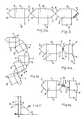
- a stone basket element 1 according to the invention according to FIG. 1 consists of a front wall part 7, a rear wall part 4 extending parallel thereto, right side wall parts 2, 3, left side wall parts 5, 6, a bottom wall part 8, a retaining wall part protruding outwards from the front wall part 7 9 and at least one, but preferably two the holding wall part 9 with the rear wall part 4 connecting holding rods 10, eleventh
- the stone basket element 1 consisting of the wall parts 2 to 8 has a cross-section in the form of an elongated hexagon when viewed from above (FIG. 2), wherein the front wall part 7 and the rear wall part 4 run parallel to one another.
- the right side wall parts 2 and 3 are each formed at an obtuse angle ⁇ 1, which is preferably about 135 °, to the corresponding outer edges of the front wall part 7 and the rear wall part 4 and connected at an angle ⁇ 2, which is preferably 90 ° ,
- the left side wall portions 5 and 6 are each connected to an outer edge of the front wall portion 7 and the rear wall portion 4 at the angle ⁇ 1 and connected to each other at the angle ⁇ 2.
- the wall parts 4 and 7 have the dimensions 50 or 75 or 100 by 100 cm
- the side wall parts 2 and 6 have the dimensions 16 by 50 or 75 or 100 cm
- the side wall parts 3 and 5 by the dimensions 23 by 50 or 75 or 100 cm
- the retaining wall part 9 approximately the dimensions 70 times 55 to 75 cm.
- Each wall part 2 to 8 preferably consists of a grid-shaped wire mesh.
- the individual bars of the wall parts 2 to 8 and the retaining wall part 9 at the respective crossovers are also welded together.
- the bottom wall part 8 is preferably formed integrally with the retaining wall part 9, wherein the area forming the bottom wall part 8 preferably extends over the whole or most of the length of the lower edges of the rear wall part 4 and the front wall part 7 and is connected to these edges.
- the bottom wall part 8 may also cover the entire bottom or base of the Seinkorbiatas.
- the integrally formed with the retaining wall part 9 bottom wall portion 8 is pivotally connected to its front wall portion 7 facing edge at the lower edge of the front wall portion 7, so that it to save space and easy handling during transport simply on the outside of the front wall part 7 can be pivoted.
- the region forming the retaining wall part 9 projects beyond the rear wall part 4 a predetermined length (eg 20 to 50 cm) towards the rear.
- a predetermined length eg 20 to 50 cm
- the upper ends of the support rods 10, 11 are preferably attached to the rear wall portion 4 by having their ends bent around a horizontal or vertical grid bar or about a crossing point of bars.
- the lower ends are preferably connected to the retaining wall parts 9, that their ends are bent around a parallel to the lower edge of the rear wall portion 4 extending bar or around a perpendicular to the lower edge of the rear wall portion 4 extending bar or around a cross point of bars.
- the length of the support rods 10, 11 is dimensioned such that the support wall part 9 extends in the plane of the bottom wall part 8 and perpendicular to the plane of the rear wall part 4.
- stones (not shown) are introduced from above into the space enclosed by the wall parts 2 to 8.
- the embankment forming earth and / or stone material is applied to the side of the embankment to be formed, which faces the rear wall portion 4.
- the stone basket elements 1 are configured in the illustrated hexagonal shape, resulting in accordance with the figures 3a, 3b any possibilities for the design of the walls formed from the Steinkorbelementen 1 or retaining walls.
- the stone basket elements 1 can be arranged in a row in a straight line next to each other to form a rectilinear retaining wall.
- the mutually facing end edges of the respective side wall parts 2, 3 and 5, 6 are preferably connected to each other in that two adjacent Steinkorb comprise 1 are pushed into each other in the region of their end edges, so that from above a connecting rod 12 in the overlapping region of Tip areas of the side wall parts 2, 3 and 5, 6 inserted and anchored in the ground can be. Slippage of stone basket elements 1 when filling with stones is prevented.
- the stone basket elements 1 placed against one another according to Fig. 3a can be pivoted against one another (for example around the connecting rod 12) to form an arcuate retaining wall.
- a connection of the individual stone basket elements 1 to each other is also possible in that in each tip region of the mutually facing side wall parts 2, 3 and 5, 6, a connecting rod 13, 14 is introduced or driven in the manner described above, in which case the two Connecting rods 13, 14 with the help of a surrounding ring member 15 (dotted line) are interconnected.
- This variant has the advantage that it allows the juxtaposition of two side wall parts 3, 5, as shown in Figure 3b right.
- the stone basket elements 1 resting against one another can in this case extend at an angle ⁇ 3 of 90 ° to one another.
- the individual bars are commercially available steel bars with a diameter of about 5 mm.
- the support rods 10, 11 preferably have about a diameter of about 8 mm.
- a retaining wall is preferably erected in the following manner.
- the empty stone basket elements 1 are put together in a manner corresponding to the desired shape of the wall to be created and connected to one another as explained above.
- the individual stone basket elements 1 are filled with stones.
- the embankment material or as mentioned above first a concrete layer 20 and applied thereon the embankment material. In this way creates an arbitrarily shaped and extremely stable wall.
- the stone basket element can on the top side by a not-shown cover part, which also consists of a lattice, be closed.
- a not-shown cover part which also consists of a lattice
- the rear wall part 4 and the front wall part 7 can be used be connected to one another by a plurality of reinforcing rods 16 to increase the stability, wherein the reinforcing rods 16 extend transversely to the longitudinal extent of the stone basket element 1.
- a plurality of reinforcing rods 16 are preferably provided one above the other.
- the one ends of the associated holding rods 10, 11 then preferably end in each case at the fastening locations of the reinforcing rods 16 facing them.
- the erection of the present Steinkorbelements takes place in the following manner.
- the retaining wall part 9 is placed on the ground.
- the retaining wall part 9 is hung on the front wall part 4 when the retaining wall part 9 at the same time also forms the bottom wall part 8 (see FIG. 5), or it is hung on the rear wall part 4 if the retaining wall part does not form the bottom wall part 8.
- the stone basket element is placed in the vertical position.
- the support rods 10, 11 are hooked (see Figure 1).
- the stone basket element can then be filled, backfilled and immediately loaded. It is also advantageously possible to deliver the stone basket elements with the retaining wall parts 9 already fastened.
- a further retaining wall part 9 ' in the case of particularly high stone basket elements whose height is, for example, 2 m, for example at half the height and to attach to the rear wall portion 4 in order to achieve a better grip of the stone basket element in the embankment material.
- slope material is applied and compacted onto the lower base wall part 8 so that the surface runs the compacted slope material in the fastening plane of the upper retaining wall part 9 '. This is then placed on the compacted embankment material and further embankment material is applied to the further bottom wall part 9 '.
- sound-absorbing materials eg. As mats can be arranged.
- the side wall parts 2 and 3 or 5 and 6 a side different lengths between their respective common connecting edges and the respective connecting edges with the front wall part 7 and with the rear wall part 4.
Landscapes
- Engineering & Computer Science (AREA)
- Civil Engineering (AREA)
- Structural Engineering (AREA)
- Environmental & Geological Engineering (AREA)
- Life Sciences & Earth Sciences (AREA)
- General Life Sciences & Earth Sciences (AREA)
- Mining & Mineral Resources (AREA)
- Paleontology (AREA)
- General Engineering & Computer Science (AREA)
- Architecture (AREA)
- Pit Excavations, Shoring, Fill Or Stabilisation Of Slopes (AREA)
- Revetment (AREA)
Applications Claiming Priority (1)
| Application Number | Priority Date | Filing Date | Title |
|---|---|---|---|
| DE200610041880 DE102006041880A1 (de) | 2006-09-06 | 2006-09-06 | Steinkorbelement zum Errichten von Stützmauern oder dergleichen |
Publications (3)
| Publication Number | Publication Date |
|---|---|
| EP1898005A2 true EP1898005A2 (fr) | 2008-03-12 |
| EP1898005A3 EP1898005A3 (fr) | 2009-01-28 |
| EP1898005B1 EP1898005B1 (fr) | 2012-08-08 |
Family
ID=38668651
Family Applications (1)
| Application Number | Title | Priority Date | Filing Date |
|---|---|---|---|
| EP20070017403 Not-in-force EP1898005B1 (fr) | 2006-09-06 | 2007-09-05 | Elément de gabion pour le montage de murs de soutènement ou analogues |
Country Status (2)
| Country | Link |
|---|---|
| EP (1) | EP1898005B1 (fr) |
| DE (1) | DE102006041880A1 (fr) |
Cited By (1)
| Publication number | Priority date | Publication date | Assignee | Title |
|---|---|---|---|---|
| ITVI20090265A1 (it) * | 2009-10-30 | 2011-04-30 | Gassa Gaetano Dalla | Elemento di armatura per il contenimento di terreni e struttura di contenimento realizzata utilizzando tali elementi di armatura |
Families Citing this family (1)
| Publication number | Priority date | Publication date | Assignee | Title |
|---|---|---|---|---|
| DE202008010662U1 (de) | 2008-08-12 | 2008-10-16 | Strobel, Meikel | Steinkorb |
Citations (5)
| Publication number | Priority date | Publication date | Assignee | Title |
|---|---|---|---|---|
| DE8608720U1 (de) | 1985-04-10 | 1986-06-05 | Füllemann + Co, Gossau | Steinkorb, insbesondere für Stütz- und Futtermauern |
| US5472297A (en) | 1989-04-07 | 1995-12-05 | Hesco Bastion Limited | Building and shoring blocks |
| WO2000040810A1 (fr) | 1999-01-08 | 2000-07-13 | Hesco Bastion Limited | Ameliorations de structures de cages |
| DE20213129U1 (de) | 2002-08-22 | 2002-11-14 | Bosshard + Staerkle Ag, Zug | Steinkorb zur Errichtung einer Lärmschutzwand |
| US20050286980A1 (en) | 2004-06-23 | 2005-12-29 | Hilfiker Harold K | Compressible welded wire retaining wall and rock face for earthen formations |
Family Cites Families (9)
| Publication number | Priority date | Publication date | Assignee | Title |
|---|---|---|---|---|
| JPS58178726A (ja) * | 1982-04-12 | 1983-10-19 | Furii Kogyo Kk | 法面保護方法 |
| FR2601399B3 (fr) * | 1986-07-10 | 1988-08-12 | Fullemann Co | Corbeille d'empierrement, notamment pour la realisation de murs de soutenement et de revetement. |
| IT1264876B1 (it) * | 1993-06-22 | 1996-10-17 | Rdb Plastotecnica Spa | Procedimento per la realizzazione di una stuttura a celle per il contenimento di materiale incoerente per la stabilizzazione ed il |
| JP3495781B2 (ja) * | 1994-05-30 | 2004-02-09 | 株式会社ジオシステム | 植生土留構造 |
| DE29802378U1 (de) * | 1998-02-12 | 1998-06-25 | Nacken, Hubert, 78256 Steißlingen | Vorrichtung zum Befüllen von Körben, insbesondere von Gabionenkörben |
| AU6457799A (en) * | 1998-11-20 | 2000-06-13 | Sytec Bausysteme Ag | Support wall system |
| FR2807456B1 (fr) * | 2000-04-10 | 2004-09-03 | Joseph Golcheh | Dispositif de soutenement et/ou de stabilisation de mur, merlon, talus |
| FR2825392B3 (fr) * | 2001-05-31 | 2003-03-21 | Pierre Roger Yvon Cuisset | Protection vis-a-vis de l'incendie par gabions grillages ancres des ouvrages de terres renforces par des geotextiles ou produits assimiles |
| DE20218701U1 (de) * | 2002-11-25 | 2003-02-13 | Rothfuss, Thomas, 71735 Eberdingen | Gabionenwand |
-
2006
- 2006-09-06 DE DE200610041880 patent/DE102006041880A1/de not_active Withdrawn
-
2007
- 2007-09-05 EP EP20070017403 patent/EP1898005B1/fr not_active Not-in-force
Patent Citations (5)
| Publication number | Priority date | Publication date | Assignee | Title |
|---|---|---|---|---|
| DE8608720U1 (de) | 1985-04-10 | 1986-06-05 | Füllemann + Co, Gossau | Steinkorb, insbesondere für Stütz- und Futtermauern |
| US5472297A (en) | 1989-04-07 | 1995-12-05 | Hesco Bastion Limited | Building and shoring blocks |
| WO2000040810A1 (fr) | 1999-01-08 | 2000-07-13 | Hesco Bastion Limited | Ameliorations de structures de cages |
| DE20213129U1 (de) | 2002-08-22 | 2002-11-14 | Bosshard + Staerkle Ag, Zug | Steinkorb zur Errichtung einer Lärmschutzwand |
| US20050286980A1 (en) | 2004-06-23 | 2005-12-29 | Hilfiker Harold K | Compressible welded wire retaining wall and rock face for earthen formations |
Cited By (1)
| Publication number | Priority date | Publication date | Assignee | Title |
|---|---|---|---|---|
| ITVI20090265A1 (it) * | 2009-10-30 | 2011-04-30 | Gassa Gaetano Dalla | Elemento di armatura per il contenimento di terreni e struttura di contenimento realizzata utilizzando tali elementi di armatura |
Also Published As
| Publication number | Publication date |
|---|---|
| EP1898005B1 (fr) | 2012-08-08 |
| EP1898005A3 (fr) | 2009-01-28 |
| DE102006041880A1 (de) | 2008-03-27 |
Similar Documents
| Publication | Publication Date | Title |
|---|---|---|
| EP1925738B1 (fr) | Mur fait de panneaux et de poteaux délimitant un volume remplissable | |
| EP1321585B1 (fr) | Treillis, notamment pour des gabions | |
| EP1064433A1 (fr) | Paroi, notamment paroi protectrice | |
| DE8916082U1 (de) | Schotterkorb-Bausatz | |
| AT414000B (de) | Auflageleiste, heiz- bzw. kühlregister sowie flächiger bauteil aus aushärtbarem werkstoff | |
| EP1898005B1 (fr) | Elément de gabion pour le montage de murs de soutènement ou analogues | |
| DE202007011315U1 (de) | Schalungselement | |
| CH707356A2 (de) | Betonfertigbauteil zur Erstellung einer Schutzwand. | |
| EP2385189B1 (fr) | Elément de coffrage | |
| EP2292846B1 (fr) | Agencement de gabion | |
| EP1131498A1 (fr) | Ensemble paroi de soutenement | |
| DE202006017921U1 (de) | Wand aus einen Füllraum begrenzenden Tafeln und Pfosten | |
| DE4409538A1 (de) | Einrichtung zum Erstellen vorzugsweise begrünbarer Böschungen | |
| EP1932978B1 (fr) | Elément d'armature pour l'absorption de forces dans des plaques de béton dans la zone d'éléments d'appui | |
| AT503358A2 (de) | Anschlusskorb für vorfabrizierte doppelwandelemente | |
| EP2312062B1 (fr) | Gabione | |
| DE29823733U1 (de) | Gitterkonstruktion zum Hinterfüllen mit Schüttmaterial | |
| DE202005003420U1 (de) | Gabionenzaundrahtgeflecht | |
| DE20207327U1 (de) | Vorbau für Fassaden von Gebäuden | |
| EP2336430A1 (fr) | Gabion | |
| DE102009041731A1 (de) | Pfosten einer Wand aus einen Füllraum begrenzenden Tafeln und Pfosten | |
| EP0566539A1 (fr) | Armature pour maçonnerie | |
| DE202013011136U1 (de) | Betonfertigbauteil zur Erstellung einer Schutzwand | |
| EP1987211A1 (fr) | Element de construction | |
| DE202017106103U1 (de) | Drahtkorb und Schutzwand gegen Lärm und/oder Hochwasser |
Legal Events
| Date | Code | Title | Description |
|---|---|---|---|
| PUAI | Public reference made under article 153(3) epc to a published international application that has entered the european phase |
Free format text: ORIGINAL CODE: 0009012 |
|
| AK | Designated contracting states |
Kind code of ref document: A2 Designated state(s): AT BE BG CH CY CZ DE DK EE ES FI FR GB GR HU IE IS IT LI LT LU LV MC MT NL PL PT RO SE SI SK TR |
|
| AX | Request for extension of the european patent |
Extension state: AL BA HR MK YU |
|
| PUAL | Search report despatched |
Free format text: ORIGINAL CODE: 0009013 |
|
| AK | Designated contracting states |
Kind code of ref document: A3 Designated state(s): AT BE BG CH CY CZ DE DK EE ES FI FR GB GR HU IE IS IT LI LT LU LV MC MT NL PL PT RO SE SI SK TR |
|
| AX | Request for extension of the european patent |
Extension state: AL BA HR MK RS |
|
| 17P | Request for examination filed |
Effective date: 20090723 |
|
| AKX | Designation fees paid |
Designated state(s): AT BE BG CH CY CZ DE DK EE ES FI FR GB GR HU IE IS IT LI LT LU LV MC MT NL PL PT RO SE SI SK TR |
|
| 17Q | First examination report despatched |
Effective date: 20090915 |
|
| GRAP | Despatch of communication of intention to grant a patent |
Free format text: ORIGINAL CODE: EPIDOSNIGR1 |
|
| GRAS | Grant fee paid |
Free format text: ORIGINAL CODE: EPIDOSNIGR3 |
|
| GRAA | (expected) grant |
Free format text: ORIGINAL CODE: 0009210 |
|
| AK | Designated contracting states |
Kind code of ref document: B1 Designated state(s): AT BE BG CH CY CZ DE DK EE ES FI FR GB GR HU IE IS IT LI LT LU LV MC MT NL PL PT RO SE SI SK TR |
|
| REG | Reference to a national code |
Ref country code: GB Ref legal event code: FG4D Free format text: NOT ENGLISH |
|
| REG | Reference to a national code |
Ref country code: AT Ref legal event code: REF Ref document number: 569878 Country of ref document: AT Kind code of ref document: T Effective date: 20120815 Ref country code: CH Ref legal event code: EP |
|
| REG | Reference to a national code |
Ref country code: IE Ref legal event code: FG4D Free format text: LANGUAGE OF EP DOCUMENT: GERMAN |
|
| REG | Reference to a national code |
Ref country code: DE Ref legal event code: R096 Ref document number: 502007010330 Country of ref document: DE Effective date: 20120927 |
|
| REG | Reference to a national code |
Ref country code: NL Ref legal event code: VDEP Effective date: 20120808 |
|
| REG | Reference to a national code |
Ref country code: LT Ref legal event code: MG4D Effective date: 20120808 |
|
| PG25 | Lapsed in a contracting state [announced via postgrant information from national office to epo] |
Ref country code: FI Free format text: LAPSE BECAUSE OF FAILURE TO SUBMIT A TRANSLATION OF THE DESCRIPTION OR TO PAY THE FEE WITHIN THE PRESCRIBED TIME-LIMIT Effective date: 20120808 Ref country code: CY Free format text: LAPSE BECAUSE OF FAILURE TO SUBMIT A TRANSLATION OF THE DESCRIPTION OR TO PAY THE FEE WITHIN THE PRESCRIBED TIME-LIMIT Effective date: 20120808 Ref country code: LT Free format text: LAPSE BECAUSE OF FAILURE TO SUBMIT A TRANSLATION OF THE DESCRIPTION OR TO PAY THE FEE WITHIN THE PRESCRIBED TIME-LIMIT Effective date: 20120808 Ref country code: IS Free format text: LAPSE BECAUSE OF FAILURE TO SUBMIT A TRANSLATION OF THE DESCRIPTION OR TO PAY THE FEE WITHIN THE PRESCRIBED TIME-LIMIT Effective date: 20121208 |
|
| PG25 | Lapsed in a contracting state [announced via postgrant information from national office to epo] |
Ref country code: PL Free format text: LAPSE BECAUSE OF FAILURE TO SUBMIT A TRANSLATION OF THE DESCRIPTION OR TO PAY THE FEE WITHIN THE PRESCRIBED TIME-LIMIT Effective date: 20120808 Ref country code: GR Free format text: LAPSE BECAUSE OF FAILURE TO SUBMIT A TRANSLATION OF THE DESCRIPTION OR TO PAY THE FEE WITHIN THE PRESCRIBED TIME-LIMIT Effective date: 20121109 Ref country code: LV Free format text: LAPSE BECAUSE OF FAILURE TO SUBMIT A TRANSLATION OF THE DESCRIPTION OR TO PAY THE FEE WITHIN THE PRESCRIBED TIME-LIMIT Effective date: 20120808 Ref country code: SE Free format text: LAPSE BECAUSE OF FAILURE TO SUBMIT A TRANSLATION OF THE DESCRIPTION OR TO PAY THE FEE WITHIN THE PRESCRIBED TIME-LIMIT Effective date: 20120808 Ref country code: SI Free format text: LAPSE BECAUSE OF FAILURE TO SUBMIT A TRANSLATION OF THE DESCRIPTION OR TO PAY THE FEE WITHIN THE PRESCRIBED TIME-LIMIT Effective date: 20120808 Ref country code: PT Free format text: LAPSE BECAUSE OF FAILURE TO SUBMIT A TRANSLATION OF THE DESCRIPTION OR TO PAY THE FEE WITHIN THE PRESCRIBED TIME-LIMIT Effective date: 20121210 |
|
| REG | Reference to a national code |
Ref country code: CH Ref legal event code: NV Representative=s name: SCHLUEP | DEGEN RECHTSANWAELTE, CH |
|
| PG25 | Lapsed in a contracting state [announced via postgrant information from national office to epo] |
Ref country code: NL Free format text: LAPSE BECAUSE OF FAILURE TO SUBMIT A TRANSLATION OF THE DESCRIPTION OR TO PAY THE FEE WITHIN THE PRESCRIBED TIME-LIMIT Effective date: 20120808 |
|
| BERE | Be: lapsed |
Owner name: STOLL, JOHANN Effective date: 20120930 |
|
| PG25 | Lapsed in a contracting state [announced via postgrant information from national office to epo] |
Ref country code: RO Free format text: LAPSE BECAUSE OF FAILURE TO SUBMIT A TRANSLATION OF THE DESCRIPTION OR TO PAY THE FEE WITHIN THE PRESCRIBED TIME-LIMIT Effective date: 20120808 Ref country code: EE Free format text: LAPSE BECAUSE OF FAILURE TO SUBMIT A TRANSLATION OF THE DESCRIPTION OR TO PAY THE FEE WITHIN THE PRESCRIBED TIME-LIMIT Effective date: 20120808 Ref country code: DK Free format text: LAPSE BECAUSE OF FAILURE TO SUBMIT A TRANSLATION OF THE DESCRIPTION OR TO PAY THE FEE WITHIN THE PRESCRIBED TIME-LIMIT Effective date: 20120808 Ref country code: MC Free format text: LAPSE BECAUSE OF NON-PAYMENT OF DUE FEES Effective date: 20120930 Ref country code: ES Free format text: LAPSE BECAUSE OF FAILURE TO SUBMIT A TRANSLATION OF THE DESCRIPTION OR TO PAY THE FEE WITHIN THE PRESCRIBED TIME-LIMIT Effective date: 20121119 Ref country code: CZ Free format text: LAPSE BECAUSE OF FAILURE TO SUBMIT A TRANSLATION OF THE DESCRIPTION OR TO PAY THE FEE WITHIN THE PRESCRIBED TIME-LIMIT Effective date: 20120808 |
|
| PG25 | Lapsed in a contracting state [announced via postgrant information from national office to epo] |
Ref country code: IT Free format text: LAPSE BECAUSE OF FAILURE TO SUBMIT A TRANSLATION OF THE DESCRIPTION OR TO PAY THE FEE WITHIN THE PRESCRIBED TIME-LIMIT Effective date: 20120808 Ref country code: SK Free format text: LAPSE BECAUSE OF FAILURE TO SUBMIT A TRANSLATION OF THE DESCRIPTION OR TO PAY THE FEE WITHIN THE PRESCRIBED TIME-LIMIT Effective date: 20120808 |
|
| PLBE | No opposition filed within time limit |
Free format text: ORIGINAL CODE: 0009261 |
|
| STAA | Information on the status of an ep patent application or granted ep patent |
Free format text: STATUS: NO OPPOSITION FILED WITHIN TIME LIMIT |
|
| REG | Reference to a national code |
Ref country code: IE Ref legal event code: MM4A |
|
| REG | Reference to a national code |
Ref country code: FR Ref legal event code: ST Effective date: 20130531 |
|
| 26N | No opposition filed |
Effective date: 20130510 |
|
| GBPC | Gb: european patent ceased through non-payment of renewal fee |
Effective date: 20121108 |
|
| PG25 | Lapsed in a contracting state [announced via postgrant information from national office to epo] |
Ref country code: BG Free format text: LAPSE BECAUSE OF FAILURE TO SUBMIT A TRANSLATION OF THE DESCRIPTION OR TO PAY THE FEE WITHIN THE PRESCRIBED TIME-LIMIT Effective date: 20121108 Ref country code: BE Free format text: LAPSE BECAUSE OF NON-PAYMENT OF DUE FEES Effective date: 20120930 Ref country code: IE Free format text: LAPSE BECAUSE OF NON-PAYMENT OF DUE FEES Effective date: 20120905 |
|
| PG25 | Lapsed in a contracting state [announced via postgrant information from national office to epo] |
Ref country code: FR Free format text: LAPSE BECAUSE OF NON-PAYMENT OF DUE FEES Effective date: 20121008 |
|
| REG | Reference to a national code |
Ref country code: DE Ref legal event code: R097 Ref document number: 502007010330 Country of ref document: DE Effective date: 20130510 |
|
| PGFP | Annual fee paid to national office [announced via postgrant information from national office to epo] |
Ref country code: CH Payment date: 20130925 Year of fee payment: 7 |
|
| PG25 | Lapsed in a contracting state [announced via postgrant information from national office to epo] |
Ref country code: GB Free format text: LAPSE BECAUSE OF NON-PAYMENT OF DUE FEES Effective date: 20121108 Ref country code: MT Free format text: LAPSE BECAUSE OF FAILURE TO SUBMIT A TRANSLATION OF THE DESCRIPTION OR TO PAY THE FEE WITHIN THE PRESCRIBED TIME-LIMIT Effective date: 20120808 |
|
| PG25 | Lapsed in a contracting state [announced via postgrant information from national office to epo] |
Ref country code: TR Free format text: LAPSE BECAUSE OF FAILURE TO SUBMIT A TRANSLATION OF THE DESCRIPTION OR TO PAY THE FEE WITHIN THE PRESCRIBED TIME-LIMIT Effective date: 20120808 |
|
| PG25 | Lapsed in a contracting state [announced via postgrant information from national office to epo] |
Ref country code: LU Free format text: LAPSE BECAUSE OF NON-PAYMENT OF DUE FEES Effective date: 20120905 |
|
| PG25 | Lapsed in a contracting state [announced via postgrant information from national office to epo] |
Ref country code: HU Free format text: LAPSE BECAUSE OF FAILURE TO SUBMIT A TRANSLATION OF THE DESCRIPTION OR TO PAY THE FEE WITHIN THE PRESCRIBED TIME-LIMIT Effective date: 20070905 |
|
| PGFP | Annual fee paid to national office [announced via postgrant information from national office to epo] |
Ref country code: AT Payment date: 20140930 Year of fee payment: 8 |
|
| REG | Reference to a national code |
Ref country code: CH Ref legal event code: PL |
|
| PG25 | Lapsed in a contracting state [announced via postgrant information from national office to epo] |
Ref country code: CH Free format text: LAPSE BECAUSE OF NON-PAYMENT OF DUE FEES Effective date: 20140930 Ref country code: LI Free format text: LAPSE BECAUSE OF NON-PAYMENT OF DUE FEES Effective date: 20140930 |
|
| REG | Reference to a national code |
Ref country code: AT Ref legal event code: MM01 Ref document number: 569878 Country of ref document: AT Kind code of ref document: T Effective date: 20150905 |
|
| PG25 | Lapsed in a contracting state [announced via postgrant information from national office to epo] |
Ref country code: AT Free format text: LAPSE BECAUSE OF NON-PAYMENT OF DUE FEES Effective date: 20150905 |
|
| PGFP | Annual fee paid to national office [announced via postgrant information from national office to epo] |
Ref country code: DE Payment date: 20181129 Year of fee payment: 12 |
|
| REG | Reference to a national code |
Ref country code: DE Ref legal event code: R119 Ref document number: 502007010330 Country of ref document: DE |
|
| PG25 | Lapsed in a contracting state [announced via postgrant information from national office to epo] |
Ref country code: DE Free format text: LAPSE BECAUSE OF NON-PAYMENT OF DUE FEES Effective date: 20200401 |