EP1898042A2 - Rohrförmige Antriebsvorrichtung zum Auf- und Abwickeln einer Verdunkelungsvorrichtung, insbesondere eines Rollladens oder dergleichen - Google Patents
Rohrförmige Antriebsvorrichtung zum Auf- und Abwickeln einer Verdunkelungsvorrichtung, insbesondere eines Rollladens oder dergleichen Download PDFInfo
- Publication number
- EP1898042A2 EP1898042A2 EP07016233A EP07016233A EP1898042A2 EP 1898042 A2 EP1898042 A2 EP 1898042A2 EP 07016233 A EP07016233 A EP 07016233A EP 07016233 A EP07016233 A EP 07016233A EP 1898042 A2 EP1898042 A2 EP 1898042A2
- Authority
- EP
- European Patent Office
- Prior art keywords
- drive device
- electric motor
- housing
- inner sleeve
- winding tube
- Prior art date
- Legal status (The legal status is an assumption and is not a legal conclusion. Google has not performed a legal analysis and makes no representation as to the accuracy of the status listed.)
- Granted
Links
Images

Classifications
-
- E—FIXED CONSTRUCTIONS
- E06—DOORS, WINDOWS, SHUTTERS, OR ROLLER BLINDS IN GENERAL; LADDERS
- E06B—FIXED OR MOVABLE CLOSURES FOR OPENINGS IN BUILDINGS, VEHICLES, FENCES OR LIKE ENCLOSURES IN GENERAL, e.g. DOORS, WINDOWS, BLINDS, GATES
- E06B9/00—Screening or protective devices for wall or similar openings, with or without operating or securing mechanisms; Closures of similar construction
- E06B9/56—Operating, guiding or securing devices or arrangements for roll-type closures; Spring drums; Tape drums; Counterweighting arrangements therefor
- E06B9/68—Operating devices or mechanisms, e.g. with electric drive
- E06B9/72—Operating devices or mechanisms, e.g. with electric drive comprising an electric motor positioned inside the roller
- E06B2009/725—Operating devices or mechanisms, e.g. with electric drive comprising an electric motor positioned inside the roller with epicyclic or planetary gear train
Definitions
- the invention relates to a tubular drive device for winding and unwinding of a darkening device, in particular a roller shutter or the like., Comprising one or the like in the winding tube of the shutter.
- usable housing in which an electric motor is integrated with an adjoining gear.
- the device for switching off the drive in its respective positions has the disadvantage that after leaving the limit switch, the position of the roller shutter can not be detected by the controller. There is thus no obstacle monitoring, at least not when driving down the Roller shutter. Only after reaching one of the limit switches, the controller recognizes the current position again.
- the invention is therefore an object of the invention to provide a drive device of the type specified, which is relatively compact, which requires relatively few items and thus also reduces the friction and the manufacturing costs, which includes a displacement measurement for detecting the instantaneous position of the shutter and the Assembly is ensured with relatively little effort.
- the drive device according to the invention is characterized in particular by the fact that the use of a 24V electric motor and the subsequent compact transmission, a compact unit is created, which even allows the integration of the controller in the drive device, the overall length of the entire drive device, however, much shorter is than in conventional drive devices or tubular motors.
- Retrofitting a drive device for shutters, which were previously brought by hand on a webbing and a Gurtwickler in their respective position is relatively easy. Due to the interchangeability of the bearing pin of the same can be replaced by a bearing pin, as he was present before installation of the drive device. This is inventively made possible by the fact that a separate torque arm is provided.
- tubular drive device 1 for winding and unwinding a Dimming device for winding and unwinding a Dimming device, in particular a roller shutter or the like.
- a Dimming device in particular a roller shutter or the like.
- usable housing 3 in which an electric motor 4 is integrated with an adjoining transmission 5.
- the housing 3 is non-positively and / or positively connected to the winding tube 2 and freely rotatably mounted on an inner sleeve 6 coaxially.
- the inner sleeve 6 is secured on its side facing to one of the side bearings 7 of the winding tube 2 side 8 via a torque arm 9 against rotation. On the torque arm 9 will be discussed later again.
- the electric motor 4 is inserted on the side 11 of the inner sleeve 6 facing away from the lateral support 7 of the winding sleeve 2 and connected to the inner sleeve 6.
- the electric motor 4, which is acted upon by a voltage of 24 volts, drives via the transmission 5, which is designed as a planetary gear, the housing 3 with the winding tube 2 and the shutter.
- the gear 5 or planetary gear consists of a mounted on the drive shaft 12 of the electric motor 4 and driven by the same sun gear 13, which drives at least two planetary gears 14.
- three planet gears 14 are provided.
- the one 22 of the two sprockets 22, 23rd firmly connected to the inner sleeve 6 and the other ring gear 23 fixedly connected to the housing 3 and drives the housing 3 and thus the winding tube 2 to the shutter.
- the other ring gear 23 is inserted in a coaxial bore 24 of the housing 3 and secured in the bore 24 along grooves 25 like a spline with the housing 3 against rotation.
- Against longitudinal displacement of the other sprocket 23 is connected via radially inserted screws 26 with the housing 3, wherein the winding tube 2 is connected via at least one further radially inserted screw 27 with the housing 3 and possibly the other sprocket 23.
- the controller 28 of the drive device 1 is inserted in the inner sleeve 6 on the directed to the bearing 7 of the winding tube 2 side 8 in the longitudinal center bore 10 of the inner sleeve 6.
- the longitudinal center bore 10 of the inner sleeve 6 has longitudinal grooves 29 into which the controller 28 is inserted via a circuit board 30 into the longitudinal center bore 10.
- the board 30 extends to the rear end 31 of the electric motor 4.
- Anschlußflachstecker (not shown) are provided which are pushed upon insertion of the board 30 to fixed (also not shown) mating connector of the electric motor 4 and record this, whereby the direct connection of the electric motor 4 ensures is.
- the drive shaft 12 of the electric motor 4 protrudes on both sides of the housing 36 of the electric motor 4, wherein on the part 37 of the drive shaft 12 which is located on the side facing away from the transmission 3 side 38 of the electric motor 4, a pulse generator 39 is arranged, the one on the board 30 arranged sensor 40 or the like. is provided for measuring the distance of the roller shutter. Due to the pulse generator 39 and the associated sensor 40 or the like. in connection with the controller 28, the control is informed of the exact position of the shutter, the accuracy being ⁇ 2 mm.
- a holding brake 41 is preferably arranged on the part 37 of the drive shaft 12, which is located on the side facing away from the transmission 3 side 38 of the electric motor 4, a holding brake 41 is preferably arranged.
- This holding brake 41 ensures that the roller shutter is held securely, especially in intermediate positions.
- the holding brake 41 can be designed as a mechanical brake, as a magnet-operated brake and as a spring-actuated brake. But it can also serve as an electrical position control as a brake, wherein the previously described pulse generator 39 and the sensor 40 or the like. in conjunction with the controller 28 find an additional application.
- the already mentioned torque arm 9, which secures the inner sleeve 6 with the electric motor 4 against rotation, on the one hand on the longitudinal central bore 10 occlusive cover 33 is fixed non-positively.
- a bearing pin 42 is arranged interchangeable as a lateral support 7 of the winding tube 2.
- This bearing pin 42 can in the common designs (see Fig. 1 and 2) may be formed, so that a simple change of manually operated shutters on electric motor driven shutters is very easily possible without changing the wall-side storage.
- the electrical connection of the drive device 1 is relatively simple, since the controller is already in the drive device 1. There is only one power supply to be created.
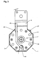
- a cable 43 is attached to the board 30, which is led out via a rubber grommet 44 from the lid 33. In a slot 45 (Fig. 3) of the torque arm 9, the cable 43 may be additionally guided.
- the drive device 1 can optionally be controlled by means of a radio remote control. But it is also possible to control via mounted in or on the wall switch. For this purpose, only control lines must be led to the switch.
- the roller shutter After assembly of the drive device 1, the roller shutter is raised to "teach in” the controller 28.
- the controller recognizes how much power is required when moving up and down in each position. If during later operation at a certain point the current deviates by a certain value, the electric motor 4 is switched off. This can be the case, for example, when the roller shutter jams in its guide rail.
Landscapes
- Engineering & Computer Science (AREA)
- Structural Engineering (AREA)
- Architecture (AREA)
- Civil Engineering (AREA)
- Operating, Guiding And Securing Of Roll- Type Closing Members (AREA)
- Preliminary Treatment Of Fibers (AREA)
- Blinds (AREA)
Abstract
Description
- Die Erfindung bezieht sich auf eine rohrförmige Antriebsvorrichtung zum Auf- und Abwickeln einer Verdunkelungsvorrichtung, insbesondere eines Rollladens o.dgl., bestehend aus einem in die Wickelhülse des Rollladens o.dgl. einsetzbaren Gehäuse, in dem ein Elektromotor mit einem daran anschließenden Getriebe integriert ist.
- Übliche bekannte Antriebsvorrichtungen bzw. Rohrmotore sind aufgrund ihrer Konstruktion sehr lang ausgebildet. Dies kommt daher, dass zum einen die Antriebsseite einen Motor mit mehreren hintereinander angeordneten Getriebesätzen mit entsprechend hohen Reibungsverlusten aufweist, wobei zusätzlich auch noch ein Kondensator für den Motor benötigt wird. Zum anderen ist eine Einrichtung vorgesehen, die den Rohrmotor in dessen Endlagen abschaltet. Dazu wird z.B. eine Spindel mit Mutter verwendet, wobei Endschalter vorgesehen sind, die die beiden Endlagen des Antriebs bilden und diesen abschalten. Sämtliche Komponenten sind hintereinander angeordnet, wodurch sich die Länge der Antriebsvorrichtung bzw. des Rohrmotors ergibt.
- Außerdem weist die Einrichtung zum Abschalten des Antriebs in seinen jeweiligen Positionen den Nachteil auf, dass nach dem Verlassen der Endschalter die Position des Rollladen nicht von der Steuerung erkannt werden kann. Es gibt somit auch keine Hindernisüberwachung, zumindest nicht beim Runterfahren des Rollladens. Erst nach dem Erreichen eines der Endschalter erkennt die Steuerung wieder die augenblickliche Position.
- Der Erfindung liegt daher die Aufgabe zugrunde, eine Antriebsvorrichtung der angegebenen Gattung zu schaffen, die relativ kompakt ausgebildet ist, die relativ wenig Einzelteile benötigt und somit auch die Reibleistung und die Herstellkosten verringert, die eine Wegmessung zur Erfassung der augenblicklichen Position des Rollladens beinhaltet und dessen Montage mit relativ geringem Aufwand gewährleistet ist.
- Diese Aufgabe wird erfindungsgemäß durch eine Antriebsvorrichtung mit den Kennzeichnungsmerkmalen des Patentanspruchs 1 gelöst.
- Zweckmäßige Weiterbildungen der Erfindung sind in den Unteransprüchen gekennzeichnet.
- Die erfindungsgemäße Antriebsvorrichtung zeichnet sich vor allem dadurch aus, dass durch die Verwendung eines 24V-Elektromotors und des daran anschließenden kompakten Getriebes eine kompakte Baueinheit entsteht, die sogar noch die Integration der Steuerung in die Antriebsvorrichtung ermöglicht, wobei die Baulänge der gesamten Antriebsvorrichtung trotzdem wesentlich kürzer ist als bei herkömmlichen Antriebsvorrichtungen bzw. Rohrmotoren.
- Durch die relativ geringe Anzahl von Einzelteilen werden die Herstellkosten einer solchen Antriebsvorrichtung wesentlich verringert, da auch die Montagezeit wesentlich reduziert ist. Die integrierte Wegmessung ermöglicht der Steuerung, die genaue Position des Rollladens zu erkennen.
- Eine Nachrüstung einer Antriebsvorrichtung bei Rollläden, die zuvor von Hand über ein Gurtband und einen Gurtwickler in ihre jeweilige Position gebracht wurden, ist relativ einfach möglich. Durch die Auswechselbarkeit des Lagerbolzens kann derselbe durch einen Lagerbolzen ersetzt werden, wie er vor Einbau der Antriebsvorrichtung vorhanden war. Dies wird erfindungsgemäß dadurch ermöglicht, dass eine separate Drehmomentstütze vorgesehen ist.
- Weitere Vorteile der Erfindung ergeben sich aus der nachfolgenden Beschreibung anhand eines die Erfindung wiedergebenden und in der Zeichnung dargestellten Ausführungsbeispieles. Dabei zeigt
- Fig. 1
- einen Längsschnitt einer erfindungsgemäßen Antriebsvorrichtung,
- Fig. 2
- den Ausschnitt II in Fig. 1 mit einem anderen Ausführungsbeispiel eines Lagerbolzens,
- Fig. 3
- eine vergrößerte Ansicht in Richtung des Pfeiles III in Fig. 1,
- Fig. 4
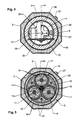
- einen vergrößerten Schnitt IV-IV in Fig. 1;
- Fig. 5
- einen vergrößerten Schnitt V-V in Fig. 1;
- Fig. 6
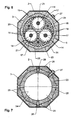
- einen vergrößerten Schnitt VI-VI in Fig. 1 und
- Fig. 7
- einen vergrößerten Schnitt VII-VII in Fig. 1.
- Die in den Figuren dargestellte rohrförmige Antriebsvorrichtung 1 zum Auf- und Abwickeln einer Verdunkelungsvorrichtung, insbesondere eines Rollladens o.dgl. besteht aus einem in eine Wickelhülse 2 des Rollladens o.dgl. einsetzbaren Gehäuse 3, in dem ein Elektromotor 4 mit einem daran anschließenden Getriebe 5 integriert ist.
- Das Gehäuse 3 ist kraft- und/oder formschlüssig mit der Wickelhülse 2 verbunden und frei drehbar auf einer Innenhülse 6 koaxial gelagert ist. Dabei ist die Innenhülse 6 an ihrer zu einer der seitlichen Lagerungen 7 der Wickelhülse 2 gerichteten Seite 8 über eine Drehmomentstütze 9 gegen Drehung gesichert. Auf die Drehmomentstütze 9 wird später nochmals eingegangen.
- In einer koaxialen Längsmittelbohrung 10 der Innenhülse 6 ist auf der von der seitlichen Lagerung 7 der Wickelhülse 2 abgewandten Seite 11 der Innenhülse 6 der Elektromotor 4 eingesetzt und mit der Innenhülse 6 verbunden. Der Elektromotor 4, der mit einer Spannung von 24 Volt beaufschlagt wird, treibt über das Getriebe 5, das als Planetengetriebe ausgebildet ist, das Gehäuse 3 mit der Wickelhülse 2 und dem Rollladen an.
- Das Getriebe 5 bzw. Planetengetriebe besteht aus einem auf die Antriebswelle 12 des Elektromotors 4 aufgesetzten und durch dieselbe angetriebenen Sonnenrad 13, das mindestens zwei Planetenräder 14 antreibt. In dem hier beschriebenen Ausführungsbeispiel sind drei Planetenräder 14 vorgesehen. Die Planetenräder 14, die in zwei Lagerhalbschalen 15, 16 ihrerseits um Lagerbolzen 17 drehbar gelagert sind, bestehen jeweils aus zwei hintereinander angeordneten, koaxial miteinander verbundenen (in Fig. 1 einstückig dargestellt), unterschiedliche Teilkreise und unterschiedliche Anzahl von Zähnen 18, 19 aufweisenden Zähnrädern 20, 21, die sich wiederum jeweils in zwei koaxial innenverzahnten, getrennten Zahnkränzen 22, 23 abwälzen. Dabei ist der eine 22 der beiden Zahnkränze 22, 23 fest mit der Innenhülse 6 verbunden und der andere Zahnkranz 23 fest mit dem Gehäuse 3 verbunden und treibt das Gehäuse 3 und somit die Wickelhülse 2 mit dem Rollladen an.
- Der andere Zahnkranz 23 ist in einer koaxialen Bohrung 24 des Gehäuses 3 eingesetzt und über in der Bohrung 24 längsverlaufende Nuten 25 keilwellenartig mit dem Gehäuse 3 gegen Verdrehen gesichert. Gegen Längsverschiebung ist der andere Zahnkranz 23 über radial eingesetzte Schrauben 26 mit dem Gehäuse 3 verbunden, wobei auch die Wickelhülse 2 über mindestens eine weitere radial eingesetzte Schraube 27 mit dem Gehäuse 3 und ggf. dem anderen Zahnkranz 23 verbunden ist.
- Die Steuerung 28 der Antriebsvorrichtung 1 ist in der Innenhülse 6 auf der zu der Lagerung 7 der Wickelhülse 2 gerichteten Seite 8 in die Längsmittelbohrung 10 der Innenhülse 6 eingesetzt. Dazu weist die Längsmittelbohrung 10 der Innenhülse 6 Längsnuten 29 auf, in die die Steuerung 28 über eine Platine 30 in die Längsmittelbohrung 10 eingeschoben ist. Dabei erstreckt sich die Platine 30 bis zum hinteren Ende 31 des Elektromotors 4. Für einen sicheren Halt der Platine 30 mit der Steuerung 28 ist die Platine 30 zwischen einem die Öffnung 32 der Längsmittelbohrung 10 der Innenhülse 6 verschließenden Deckel 33 und den Enden 34 der Längsnuten 29 eingespannt.
- Auf der dem Elektromotor 4 zugewandten Seite 35 der Platine 30 sind Anschlussflachstecker (nicht dargestellt) vorgesehen, die beim Einschieben der Platine 30 auf feststehende (ebenfalls nicht dargestellte) Gegenstecker des Elektromotors 4 aufgeschoben werden und diese aufnehmen, wodurch der direkte Anschluss des Elektromotors 4 gewährleistet ist.
- Die Antriebswelle 12 des Elektromotors 4 ragt beiderseits aus dem Gehäuse 36 des Elektromotors 4 heraus, wobei auf dem Teil 37 der Antriebswelle 12, der auf der vom Getriebe 3 abgewandten Seite 38 des Elektromotors 4 liegt, ein Impulsgeber 39 angeordnet ist, der über einen auf der Platine 30 angeordneten Sensor 40 o.dgl. zur Wegmessung des Rollladens vorgesehen ist. Aufgrund des Impulsgebers 39 und des zugehörigen Sensors 40 o.dgl. im Zusammenhang mit der Steuerung 28 wird der Steuerung die genaue Position des Rollladens übermittelt, wobei die Genauigkeit ±2 mm beträgt.
- Auf dem Teil 37 der Antriebswelle 12, der auf der vom Getriebe 3 abgewandten Seite 38 des Elektromotors 4 liegt, ist vorzugsweise auch eine Haltebremse 41 angeordnet. Diese Haltebremse 41 sorgt dafür, dass der Rollladen vor allem in Zwischenpositionen sicher gehalten wird. Die Haltebremse 41 kann als mechanische Bremse, als magnetbetätigte Bremse sowie als federkraftbetätigte Bremse ausgebildet sein. Es kann aber auch eine elektrische Lageregelung als Bremse dienen, wobei der zuvor beschriebene Impulsgeber 39 und der Sensor 40 o.dgl. in Verbindung mit der Steuerung 28 eine zusätzliche Anwendung finden.
- Die bereits erwähnte Drehmomentstütze 9, die die Innenhülse 6 mit dem Elektromotor 4 gegen Verdrehen sichert, ist einerseits auf dem die Längsmittelbohrung 10 verschließenden Deckel 33 kraftschlüssig befestigt. Andererseits wird die Drehmomentstütze 9 beispielsweise an der seitlichen Wand des jeweiligen Rollladenkastens mittels Schrauben o.dgl. befestigt.
- An der Drehmomentstütze 9 ist ein Lagerbolzen 42 als seitliche Lagerung 7 der Wickelhülse 2 auswechselbar angeordnet. Dieser Lagerbolzen 42 kann in den gängigen Ausführungen (siehe Fig. 1 und 2) ausgebildet sein, so dass ein einfaches Wechseln von handbetriebenen Rollläden auf elektromotorisch angetriebene Rollläden sehr leicht ohne Änderung der wandseitigen Lagerung möglich ist.
- Auch der elektrische Anschluss der Antriebsvorrichtung 1 gestaltet sich relativ einfach, da sich die Steuerung bereits in der Antriebsvorrichtung 1 befindet. Es muß lediglich eine Stromzufuhr geschaffen werden. Dazu ist an der Platine 30 ein Kabel 43 angebracht, das über eine Gummitülle 44 aus dem Deckel 33 herausgeführt wird. In einem Schlitz 45 (Fig. 3) der Drehmomentstütze 9 kann das Kabel 43 zusätzlich geführt sein. Über ein entsprechendes Modul in der Steuerung 28 kann die Antriebsvorrichtung 1 ggf. mittels einer Funkfernbedienung gesteuert werden. Es ist aber auch eine Steuerung über in oder an der Wand befestigte Schalter möglich. Dazu müssen lediglich Steuerleitungen zu dem Schalter geführt werden.
- Nach der Montage der Antriebsvorrichtung 1 wird der Rollladen zum "Einlernen" der Steuerung 28 hochgefahren. Dabei erkennt die Steuerung, wie viel Strom beim Rauf- und Runterfahren in den jeweiligen Positionen benötigt wird. Wenn beim späteren Betrieb an einer bestimmten Stelle der Strom um einen bestimmten Wert abweicht, wird der Elektromotor 4 abgeschaltet. Dies kann z.B. der Fall sein, wenn der Rollladen in seiner Führungsschiene verklemmt.
-
- 1
- rohrförmige Antriebsvorrichtung
- 2
- Wickelhülse für Rollladen
- 3
- Gehäuse von 1
- 4
- Elektromotor von 1
- 5
- Getriebe von 1
- 6
- Innenhülse von 1
- 7
- Lagerungen von 2
- 8
- zu 7 gerichtete Seite von 6
- 9
- Drehmomentstütze von 1 bzw. 6
- 10
- Längsmittelbohrung von 6
- 11
- von 7 abgewandte Seite von 6
- 12
- Antriebswelle von 5
- 13
- Sonnenrad auf 12 von 5
- 14
- Planetenräder von 5
- 15
- Lagerhalbschale für 14
- 16
- Lagerhalbschale für 14
- 17
- Lagerbolzen für 14
- 18
- Zähne von 20
- 19
- Zähne von 21
- 20
- Zahnrad von 14
- 21
- Zahnrad von 14
- 22
- Zahnkranz an 6 für 20
- 23
- Zahnkranz in 3 für 21
- 24
- koaxiale Bohrung in 3 für 23
- 25
- längsverlaufende Nuten in 24
- 26
- Schrauben in 6 und 23
- 27
- Schraube in 2, 6 und 23
- 28
- Steuerung von 1
- 29
- Längsnuten in 10
- 30
- Platine von 28
- 31
- hinteres Ende von 4
- 32
- Öffnung von 10 bei 11
- 33
- Deckel für 32
- 34
- Enden von 29
- 35
- zu 4 gerichtete Seite von 30
- 36
- Gehäuse von 4
- 37
- Teil von 12 bei 38
- 38
- von 3 abgewandte Seite von 4
- 39
- Impulsgeber auf 37
- 40
- Sensor auf 30
- 41
- Haltebremse auf 37
- 42
- Lagerbolzen
- 43
- Kabel an 30
- 44
- Gummitülle in 33
- 45
- Schlitz in 9 für 42
Claims (10)
- Rohrförmige Antriebsvorrichtung zum Auf- und Abwickeln einer Verdunkelungsvorrichtung, insbesondere eines Rollladens o.dgl., bestehend aus einem in die Wickelhülse des Rollladens o.dgl. einsetzbaren Gehäuse, in dem ein Elektromotor mit einem daran anschließenden Getriebe integriert ist, dadurch gekennzeichnet, dass das Gehäuse (3) kraft- und/oder formschlüssig mit der Wickelhülse (2) verbunden und frei drehbar auf einer Innenhülse (6) koaxial gelagert ist, wobei die Innenhülse (6) an ihrer zu einer der seitlichen Lagerungen (7) der Wickelhülse (2) gerichteten Seite (8) über eine Drehmomentstütze (9) gegen Drehung gesichert ist, dass in einer koaxialen Längsmittelbohrung (10) der Innenhülse (6) auf der von der seitlichen Lagerung (7) der Wickelhülse (2) abgewandten Seite (11) der Innenhülse (6) der Elektromotor (4) eingesetzt ist, der über das Getriebe (5), das als Planetengetriebe ausgebildet ist, das Gehäuse (3) mit der Wickelhülse (2) und den Rollladen antreibt, und dass die Steuerung (28) der Antriebsvorrichtung (1) in der Innenhülse (6) auf der der Lagerung (7) der Wickelhülse (2) zugewandten Seite (8) in die Längsmittelbohrung (10) der Innenhülse (6) eingesetzt ist.
- Antriebsvorrichtung nach Anspruch 1, dadurch gekennzeichnet, dass das Getriebe (3) bzw. Planetengetriebe aus einem auf die Antriebswelle (12) des Elektromotors (4) aufgesetzten und durch dieselbe angetriebenen Sonnenrad (13) besteht, das mindestens zwei Planetenräder (14) antreibt, die jeweils aus zwei hintereinander angeordneten, koaxial miteinander verbundenen, unterschiedliche Teilkreise und unterschiedliche Anzahl der Zähne (18, 19) aufweisenden Zahnrädern (20, 21) bestehen, die sich wiederum jeweils in zwei koaxial innenverzahnten, getrennten Zahnkränzen (22, 23) abwälzen, wobei der eine (22) der beiden Zahnkränze (22, 23) fest mit der Innenhülse (6) verbunden ist und der andere Zahnkranz (23) fest mit dem Gehäuse (3) verbunden ist und dieses antreibt.
- Antriebsvorrichtung nach Anspruch 1 oder 2, dadurch gekennzeichnet, dass der andere Zahnkranz (23) in einer koaxialen Bohrung (24) des Gehäuses (3) eingesetzt und über in der Bohrung (24) längsverlaufende Nuten (25) keilwellenartig mit dem Gehäuse (3) gegen Verdrehen gesichert ist.
- Antriebsvorrichtung nach einem der Ansprüche 1 bis 3, dadurch gekennzeichnet, dass der andere Zahnkranz (23) gegen Längsverschiebung über radial eingesetzte Schrauben (26) mit dem Gehäuse (3) verbunden ist.
- Antriebsvorrichtung nach einem der Ansprüche 1 bis 4, dadurch gekennzeichnet, dass die Steuerung (28) über eine Platine (30) in Längsnuten (29) in der Längsmittelbohrung (10) der Innenhülse (6) eingesetzt ist, wobei sich die Platine (30) bis zum hinteren Ende (31) des Elektromotors (4) erstreckt und zwischen einem die Öffnung (32) der Längsmittelbohrung (10) der Innenhülse (6) verschließenden Deckel (33) und den Enden (34) der Längsnuten (29) eingespannt ist.
- Antriebsvorrichtung nach einem der Ansprüche 1 bis 5, dadurch gekennzeichnet, dass auf der zu dem Elektromotor (4) zugewandten Seite (35) der Platine (30) Anschlussflachstecker vorgesehen sind, die entsprechende feststehende Gegenstecker des Elektromotors (4) aufnehmen.
- Antriebsvorrichtung nach einem der Ansprüche 1 bis 6, dadurch gekennzeichnet, dass der Elektromotor (4) mit einer Spannung von 24 Volt beaufschlagt wird.
- Antriebsvorrichtung nach einem der Ansprüche 1 bis 7, dadurch gekennzeichnet, dass die Antriebswelle (12) beiderseits aus dem Gehäuse (3) des Elektromotors (4) ragt, wobei auf dem Teil (37) der Antriebswelle (12), der auf der vom Getriebe (3) abgewandten Seite (38) des Elektromotors (4) liegt, ein Impulsgeber (39) angeordnet ist, der über einen auf der Platine (30) angeordneten Sensor (40) o.dgl. zur Wegmessung des Rollladens vorgesehen ist.
- Antriebsvorrichtung nach einem der Ansprüche 1 bis 8, dadurch gekennzeichnet, dass auf dem Teil (37) der Antriebswelle (12), der auf der dem Getriebe (3) abgewandten Seite (38) des Elektromotors (4) liegt, eine Haltebremse (41) angeordnet ist.
- Antriebsvorrichtung nach einem der Ansprüche 1 bis 9, dadurch gekennzeichnet, dass die Drehmomentstütze (9) auf dem die Längsmittelbohrung (10) verschließenden Deckel (33) kraftschlüssig befestigt ist und dass an der Drehmomentstütze (9) ein Lagerbolzen (42) als seitliche Lagerung (7) der Wickelhülse (2) auswechselbar angeordnet ist.
Applications Claiming Priority (1)
| Application Number | Priority Date | Filing Date | Title |
|---|---|---|---|
| DE202006013201U DE202006013201U1 (de) | 2006-08-28 | 2006-08-28 | Rohrförmige Antriebsvorrichtung zum Auf- und Abwickeln einer Verdunkelungsvorrichtung, insbesondere eines Rollladens o.dgl. |
Publications (3)
| Publication Number | Publication Date |
|---|---|
| EP1898042A2 true EP1898042A2 (de) | 2008-03-12 |
| EP1898042A3 EP1898042A3 (de) | 2009-07-22 |
| EP1898042B1 EP1898042B1 (de) | 2011-06-15 |
Family
ID=37388302
Family Applications (1)
| Application Number | Title | Priority Date | Filing Date |
|---|---|---|---|
| EP07016233A Not-in-force EP1898042B1 (de) | 2006-08-28 | 2007-08-18 | Rohrförmige Antriebsvorrichtung zum Auf- und Abwickeln einer Verdunkelungsvorrichtung, insbesondere eines Rollladens oder dergleichen |
Country Status (4)
| Country | Link |
|---|---|
| EP (1) | EP1898042B1 (de) |
| AT (1) | ATE513114T1 (de) |
| DE (1) | DE202006013201U1 (de) |
| ES (1) | ES2368007T3 (de) |
Cited By (6)
| Publication number | Priority date | Publication date | Assignee | Title |
|---|---|---|---|---|
| US20150075732A1 (en) * | 2013-09-18 | 2015-03-19 | Lutron Electronics Co., Inc. | Quiet motorized window treatment system |
| US20150300088A1 (en) * | 2012-06-13 | 2015-10-22 | Somfy Sas | Motorized manoeuvring device intended to manoeuvre a moving windable fabric screen of a window or projection screen cover device |
| US9722220B2 (en) | 2012-06-13 | 2017-08-01 | Somfy Sas | Element for mounting a battery in a winding tube of a home-automation screen |
| FR3049304A1 (fr) * | 2016-03-23 | 2017-09-29 | Zurfluh Feller | Actionneur d'une installation de fermeture, installation de fermeture comprenant un tel actionneur et procede de montage |
| CN109494937A (zh) * | 2018-12-21 | 2019-03-19 | 日电产伺服电机(常州)有限公司 | 一种自动预设位置控制电机 |
| US10597940B2 (en) | 2012-06-13 | 2020-03-24 | Somfy Sas | Motor-driven control device for controlling a movable screen consisting of a windable canvas of a window-covering device or projection screen |
Families Citing this family (10)
| Publication number | Priority date | Publication date | Assignee | Title |
|---|---|---|---|---|
| DE102007006396A1 (de) * | 2007-02-05 | 2008-08-07 | Provita Gmbh | Vorrichtung zur Stillstandssteuerung einer motorischen Antriebseinrichtung |
| ATE480688T1 (de) | 2007-06-07 | 2010-09-15 | Vkr Holding As | Wickelwelle mit rohrmotor und elektronischem bewegungssensor |
| DE202007008562U1 (de) | 2007-06-20 | 2007-08-23 | Alfred Schellenberg Gmbh | Nachrüstbarer elektrischer Antrieb für Markisen mit manueller Drehvorrichtung |
| DE202008010951U1 (de) | 2008-08-16 | 2008-10-23 | Alfred Schellenberg Gmbh | Nachrüstbarer elektrischer Antrieb für Markisen mit manueller Drehvorrichtung |
| AU2010101382B4 (en) * | 2010-02-24 | 2011-06-16 | Automatic Technology (Australia) Pty Ltd | Roller Door Drive Assembly |
| DE102011075250A1 (de) | 2011-05-04 | 2012-11-08 | Alfred Schellenberg Gmbh | Antriebsvorrichtung zum Auf- und Abwickeln einer Verdunkelungsvorrichtung, insbesondere eines Rollladens o.dgl. |
| DE102011085788B4 (de) | 2011-11-04 | 2019-09-05 | Alfred Schellenberg Gmbh | Antriebsvorrichtung zum Auf- und Abwickeln einer Verdunkelungsvorrichtung, insbesondere eines Rollladens o.dgl. |
| DE102012200037B4 (de) | 2012-01-03 | 2018-08-02 | Alfred Schellenberg Gmbh | Antriebsvorrichtung zum Auf- und Abwickeln einer Verdunkelungsvorrichtung |
| DE102012200035B4 (de) | 2012-01-03 | 2016-06-09 | Alfred Schellenberg Gmbh | Antriebsvorrichtung zum Auf- und Abwickeln einer Verdunkelungsvorrichtung, insbesondere eines Rollladens o.dgl. |
| CA2907143A1 (en) * | 2013-03-15 | 2014-09-18 | Springs Window Fashions, Llc | Window covering motorized lift and control operating system |
Citations (2)
| Publication number | Priority date | Publication date | Assignee | Title |
|---|---|---|---|---|
| US4651940A (en) | 1984-11-06 | 1987-03-24 | Sm Industrial Co., Ltd. | Screen-taking-up device |
| DE4442102A1 (de) | 1994-11-25 | 1996-07-04 | Becker Antriebe Gmbh | Antrieb für Rolladen, Rolltore, Beschattungsanlagen u. dgl. |
Family Cites Families (1)
| Publication number | Priority date | Publication date | Assignee | Title |
|---|---|---|---|---|
| DE7825175U1 (de) * | 1978-08-24 | 1987-12-17 | Goetzberger, Adolf, Prof. Dr., 7802 Merzhausen | Elektrisch betriebenes Rollo oder Rolladen |
-
2006
- 2006-08-28 DE DE202006013201U patent/DE202006013201U1/de not_active Expired - Lifetime
-
2007
- 2007-08-18 ES ES07016233T patent/ES2368007T3/es active Active
- 2007-08-18 AT AT07016233T patent/ATE513114T1/de active
- 2007-08-18 EP EP07016233A patent/EP1898042B1/de not_active Not-in-force
Patent Citations (2)
| Publication number | Priority date | Publication date | Assignee | Title |
|---|---|---|---|---|
| US4651940A (en) | 1984-11-06 | 1987-03-24 | Sm Industrial Co., Ltd. | Screen-taking-up device |
| DE4442102A1 (de) | 1994-11-25 | 1996-07-04 | Becker Antriebe Gmbh | Antrieb für Rolladen, Rolltore, Beschattungsanlagen u. dgl. |
Cited By (8)
| Publication number | Priority date | Publication date | Assignee | Title |
|---|---|---|---|---|
| US20150300088A1 (en) * | 2012-06-13 | 2015-10-22 | Somfy Sas | Motorized manoeuvring device intended to manoeuvre a moving windable fabric screen of a window or projection screen cover device |
| US9722220B2 (en) | 2012-06-13 | 2017-08-01 | Somfy Sas | Element for mounting a battery in a winding tube of a home-automation screen |
| US10597940B2 (en) | 2012-06-13 | 2020-03-24 | Somfy Sas | Motor-driven control device for controlling a movable screen consisting of a windable canvas of a window-covering device or projection screen |
| US10934773B2 (en) * | 2012-06-13 | 2021-03-02 | Somfy Activites Sa | Motorized manoeuvring device intended to manoeuvre a moving windable fabric screen of a window or projection screen cover device |
| US20150075732A1 (en) * | 2013-09-18 | 2015-03-19 | Lutron Electronics Co., Inc. | Quiet motorized window treatment system |
| US10689905B2 (en) | 2013-09-18 | 2020-06-23 | Lutron Technology Company Llc | Quiet motorized window treatment system |
| FR3049304A1 (fr) * | 2016-03-23 | 2017-09-29 | Zurfluh Feller | Actionneur d'une installation de fermeture, installation de fermeture comprenant un tel actionneur et procede de montage |
| CN109494937A (zh) * | 2018-12-21 | 2019-03-19 | 日电产伺服电机(常州)有限公司 | 一种自动预设位置控制电机 |
Also Published As
| Publication number | Publication date |
|---|---|
| EP1898042A3 (de) | 2009-07-22 |
| EP1898042B1 (de) | 2011-06-15 |
| ES2368007T3 (es) | 2011-11-11 |
| DE202006013201U1 (de) | 2006-10-26 |
| ATE513114T1 (de) | 2011-07-15 |
Similar Documents
| Publication | Publication Date | Title |
|---|---|---|
| EP1898042B1 (de) | Rohrförmige Antriebsvorrichtung zum Auf- und Abwickeln einer Verdunkelungsvorrichtung, insbesondere eines Rollladens oder dergleichen | |
| DE3110079C2 (de) | ||
| DE2823134C3 (de) | Getriebe für Rolladen und Markisen | |
| DE19750715C1 (de) | Rollovorrichtung für ein Fahrzeugdach mit transparenter Dachscheibe | |
| EP2385210B1 (de) | Planetenradgetriebe für Antriebsmotoren | |
| DE60216414T2 (de) | Kompakt-Aktuator | |
| DE69602476T2 (de) | Vorrichtung zur Befestigung einer Rolladenwelle | |
| WO2008006758A1 (de) | Antriebsbaueinheit für sonnenschutzeinrichtungen, wie rollläden, markisen und dergleichen | |
| DE1303844C2 (de) | Elektrische antriebsvorrichtung fuer rollaeden, jalousien od. dgl | |
| DE3636855A1 (de) | Untersetzungsgetriebe, insbesondere zum einbau in einen gurtkasten eines elektromotorisch angetriebenen gurtwicklers fuer einen rolladen od. dgl. | |
| EP2565364B1 (de) | Rohrförmige Antriebsvorrichtung mit einem Adapter für die Abtriebswelle zum Auf- und Abwickeln einer Verdunkelungsvorrichtung | |
| DE3220441A1 (de) | Auf eine welle aufwickelbares rollo | |
| DE3608988A1 (de) | Vorrichtung zur handbetaetigung einer elektromotorisch antreibbaren wickelwelle z.b. eines rolladens | |
| DE102006041689A1 (de) | Rohrförmige Antriebsvorrichtung zum Auf- und Abwickeln einer Verdunkelungsvorrichtung, insbesondere eines Rollladens o.dgl. | |
| DE202007002959U1 (de) | Fahrzeugfensterrollo | |
| EP2520754A2 (de) | Antrieb für einen Rolladengurt mit mehrstufigem Getriebe | |
| EP1201370B1 (de) | Elektrisch betätigbare Werkstück-Spannvorrichtung | |
| DE2803496C2 (de) | Vorrichtung zum Betätigen eines Rolladens | |
| DE10257057A1 (de) | Getriebe einer Antriebsvorrichtung einer Jalousie oder dergleichen | |
| DE102024107399B3 (de) | Antrieb für eine Tür oder ein Fenster mit verbessertem Wirkungsgrad | |
| DE69723645T2 (de) | Rolladen mit elektrischem Antrieb und ein Reduktionsgetriebe für einen solchen Rolladen | |
| DE102017116435A1 (de) | Linearantrieb mit rückensteifer Kette | |
| DE202007005514U1 (de) | Antriebssystem für eine Lamellenanordnung | |
| EP1120536A2 (de) | Motoreinheit für den Antrieb einer Jalousie | |
| DE60105626T2 (de) | Mechanisches, selbstsicherndes Getriebe, insbesondere für eine Winde |
Legal Events
| Date | Code | Title | Description |
|---|---|---|---|
| PUAI | Public reference made under article 153(3) epc to a published international application that has entered the european phase |
Free format text: ORIGINAL CODE: 0009012 |
|
| AK | Designated contracting states |
Kind code of ref document: A2 Designated state(s): AT BE BG CH CY CZ DE DK EE ES FI FR GB GR HU IE IS IT LI LT LU LV MC MT NL PL PT RO SE SI SK TR |
|
| AX | Request for extension of the european patent |
Extension state: AL BA HR MK YU |
|
| PUAL | Search report despatched |
Free format text: ORIGINAL CODE: 0009013 |
|
| AK | Designated contracting states |
Kind code of ref document: A3 Designated state(s): AT BE BG CH CY CZ DE DK EE ES FI FR GB GR HU IE IS IT LI LT LU LV MC MT NL PL PT RO SE SI SK TR |
|
| AX | Request for extension of the european patent |
Extension state: AL BA HR MK RS |
|
| 17P | Request for examination filed |
Effective date: 20100105 |
|
| 17Q | First examination report despatched |
Effective date: 20100202 |
|
| AKX | Designation fees paid |
Designated state(s): AT BE BG CH CY CZ DE DK EE ES FI FR GB GR HU IE IS IT LI LT LU LV MC MT NL PL PT RO SE SI SK TR |
|
| GRAP | Despatch of communication of intention to grant a patent |
Free format text: ORIGINAL CODE: EPIDOSNIGR1 |
|
| GRAS | Grant fee paid |
Free format text: ORIGINAL CODE: EPIDOSNIGR3 |
|
| GRAA | (expected) grant |
Free format text: ORIGINAL CODE: 0009210 |
|
| AK | Designated contracting states |
Kind code of ref document: B1 Designated state(s): AT BE BG CH CY CZ DE DK EE ES FI FR GB GR HU IE IS IT LI LT LU LV MC MT NL PL PT RO SE SI SK TR |
|
| REG | Reference to a national code |
Ref country code: GB Ref legal event code: FG4D Free format text: NOT ENGLISH Ref country code: CH Ref legal event code: EP |
|
| REG | Reference to a national code |
Ref country code: IE Ref legal event code: FG4D Free format text: LANGUAGE OF EP DOCUMENT: GERMAN |
|
| REG | Reference to a national code |
Ref country code: DE Ref legal event code: R096 Ref document number: 502007007416 Country of ref document: DE Effective date: 20110728 |
|
| REG | Reference to a national code |
Ref country code: NL Ref legal event code: VDEP Effective date: 20110615 |
|
| PG25 | Lapsed in a contracting state [announced via postgrant information from national office to epo] |
Ref country code: SE Free format text: LAPSE BECAUSE OF FAILURE TO SUBMIT A TRANSLATION OF THE DESCRIPTION OR TO PAY THE FEE WITHIN THE PRESCRIBED TIME-LIMIT Effective date: 20110615 Ref country code: LT Free format text: LAPSE BECAUSE OF FAILURE TO SUBMIT A TRANSLATION OF THE DESCRIPTION OR TO PAY THE FEE WITHIN THE PRESCRIBED TIME-LIMIT Effective date: 20110615 |
|
| REG | Reference to a national code |
Ref country code: ES Ref legal event code: FG2A Ref document number: 2368007 Country of ref document: ES Kind code of ref document: T3 Effective date: 20111111 |
|
| PG25 | Lapsed in a contracting state [announced via postgrant information from national office to epo] |
Ref country code: SI Free format text: LAPSE BECAUSE OF FAILURE TO SUBMIT A TRANSLATION OF THE DESCRIPTION OR TO PAY THE FEE WITHIN THE PRESCRIBED TIME-LIMIT Effective date: 20110615 Ref country code: FI Free format text: LAPSE BECAUSE OF FAILURE TO SUBMIT A TRANSLATION OF THE DESCRIPTION OR TO PAY THE FEE WITHIN THE PRESCRIBED TIME-LIMIT Effective date: 20110615 Ref country code: LV Free format text: LAPSE BECAUSE OF FAILURE TO SUBMIT A TRANSLATION OF THE DESCRIPTION OR TO PAY THE FEE WITHIN THE PRESCRIBED TIME-LIMIT Effective date: 20110615 Ref country code: GR Free format text: LAPSE BECAUSE OF FAILURE TO SUBMIT A TRANSLATION OF THE DESCRIPTION OR TO PAY THE FEE WITHIN THE PRESCRIBED TIME-LIMIT Effective date: 20110916 Ref country code: CY Free format text: LAPSE BECAUSE OF FAILURE TO SUBMIT A TRANSLATION OF THE DESCRIPTION OR TO PAY THE FEE WITHIN THE PRESCRIBED TIME-LIMIT Effective date: 20110615 |
|
| PG25 | Lapsed in a contracting state [announced via postgrant information from national office to epo] |
Ref country code: MT Free format text: LAPSE BECAUSE OF FAILURE TO SUBMIT A TRANSLATION OF THE DESCRIPTION OR TO PAY THE FEE WITHIN THE PRESCRIBED TIME-LIMIT Effective date: 20110615 Ref country code: NL Free format text: LAPSE BECAUSE OF FAILURE TO SUBMIT A TRANSLATION OF THE DESCRIPTION OR TO PAY THE FEE WITHIN THE PRESCRIBED TIME-LIMIT Effective date: 20110615 |
|
| REG | Reference to a national code |
Ref country code: IE Ref legal event code: FD4D |
|
| PG25 | Lapsed in a contracting state [announced via postgrant information from national office to epo] |
Ref country code: EE Free format text: LAPSE BECAUSE OF FAILURE TO SUBMIT A TRANSLATION OF THE DESCRIPTION OR TO PAY THE FEE WITHIN THE PRESCRIBED TIME-LIMIT Effective date: 20110615 Ref country code: CZ Free format text: LAPSE BECAUSE OF FAILURE TO SUBMIT A TRANSLATION OF THE DESCRIPTION OR TO PAY THE FEE WITHIN THE PRESCRIBED TIME-LIMIT Effective date: 20110615 Ref country code: PT Free format text: LAPSE BECAUSE OF FAILURE TO SUBMIT A TRANSLATION OF THE DESCRIPTION OR TO PAY THE FEE WITHIN THE PRESCRIBED TIME-LIMIT Effective date: 20111017 Ref country code: IE Free format text: LAPSE BECAUSE OF FAILURE TO SUBMIT A TRANSLATION OF THE DESCRIPTION OR TO PAY THE FEE WITHIN THE PRESCRIBED TIME-LIMIT Effective date: 20110615 Ref country code: IS Free format text: LAPSE BECAUSE OF FAILURE TO SUBMIT A TRANSLATION OF THE DESCRIPTION OR TO PAY THE FEE WITHIN THE PRESCRIBED TIME-LIMIT Effective date: 20111015 |
|
| BERE | Be: lapsed |
Owner name: ALFRED SCHELLENBERG G.M.B.H. Effective date: 20110831 |
|
| PG25 | Lapsed in a contracting state [announced via postgrant information from national office to epo] |
Ref country code: RO Free format text: LAPSE BECAUSE OF FAILURE TO SUBMIT A TRANSLATION OF THE DESCRIPTION OR TO PAY THE FEE WITHIN THE PRESCRIBED TIME-LIMIT Effective date: 20110615 Ref country code: PL Free format text: LAPSE BECAUSE OF FAILURE TO SUBMIT A TRANSLATION OF THE DESCRIPTION OR TO PAY THE FEE WITHIN THE PRESCRIBED TIME-LIMIT Effective date: 20110615 Ref country code: SK Free format text: LAPSE BECAUSE OF FAILURE TO SUBMIT A TRANSLATION OF THE DESCRIPTION OR TO PAY THE FEE WITHIN THE PRESCRIBED TIME-LIMIT Effective date: 20110615 |
|
| PG25 | Lapsed in a contracting state [announced via postgrant information from national office to epo] |
Ref country code: MC Free format text: LAPSE BECAUSE OF NON-PAYMENT OF DUE FEES Effective date: 20110831 |
|
| REG | Reference to a national code |
Ref country code: CH Ref legal event code: PL |
|
| PLBE | No opposition filed within time limit |
Free format text: ORIGINAL CODE: 0009261 |
|
| STAA | Information on the status of an ep patent application or granted ep patent |
Free format text: STATUS: NO OPPOSITION FILED WITHIN TIME LIMIT |
|
| PG25 | Lapsed in a contracting state [announced via postgrant information from national office to epo] |
Ref country code: LI Free format text: LAPSE BECAUSE OF NON-PAYMENT OF DUE FEES Effective date: 20110831 Ref country code: CH Free format text: LAPSE BECAUSE OF NON-PAYMENT OF DUE FEES Effective date: 20110831 |
|
| 26N | No opposition filed |
Effective date: 20120316 |
|
| GBPC | Gb: european patent ceased through non-payment of renewal fee |
Effective date: 20110915 |
|
| PG25 | Lapsed in a contracting state [announced via postgrant information from national office to epo] |
Ref country code: BE Free format text: LAPSE BECAUSE OF NON-PAYMENT OF DUE FEES Effective date: 20110831 |
|
| PG25 | Lapsed in a contracting state [announced via postgrant information from national office to epo] |
Ref country code: DK Free format text: LAPSE BECAUSE OF FAILURE TO SUBMIT A TRANSLATION OF THE DESCRIPTION OR TO PAY THE FEE WITHIN THE PRESCRIBED TIME-LIMIT Effective date: 20110615 |
|
| REG | Reference to a national code |
Ref country code: DE Ref legal event code: R097 Ref document number: 502007007416 Country of ref document: DE Effective date: 20120316 |
|
| PG25 | Lapsed in a contracting state [announced via postgrant information from national office to epo] |
Ref country code: GB Free format text: LAPSE BECAUSE OF NON-PAYMENT OF DUE FEES Effective date: 20110915 |
|
| PG25 | Lapsed in a contracting state [announced via postgrant information from national office to epo] |
Ref country code: LU Free format text: LAPSE BECAUSE OF NON-PAYMENT OF DUE FEES Effective date: 20110818 |
|
| PG25 | Lapsed in a contracting state [announced via postgrant information from national office to epo] |
Ref country code: BG Free format text: LAPSE BECAUSE OF FAILURE TO SUBMIT A TRANSLATION OF THE DESCRIPTION OR TO PAY THE FEE WITHIN THE PRESCRIBED TIME-LIMIT Effective date: 20110915 |
|
| PG25 | Lapsed in a contracting state [announced via postgrant information from national office to epo] |
Ref country code: TR Free format text: LAPSE BECAUSE OF FAILURE TO SUBMIT A TRANSLATION OF THE DESCRIPTION OR TO PAY THE FEE WITHIN THE PRESCRIBED TIME-LIMIT Effective date: 20110615 |
|
| REG | Reference to a national code |
Ref country code: AT Ref legal event code: MM01 Ref document number: 513114 Country of ref document: AT Kind code of ref document: T Effective date: 20120831 |
|
| PG25 | Lapsed in a contracting state [announced via postgrant information from national office to epo] |
Ref country code: AT Free format text: LAPSE BECAUSE OF NON-PAYMENT OF DUE FEES Effective date: 20120831 Ref country code: HU Free format text: LAPSE BECAUSE OF FAILURE TO SUBMIT A TRANSLATION OF THE DESCRIPTION OR TO PAY THE FEE WITHIN THE PRESCRIBED TIME-LIMIT Effective date: 20110615 |
|
| PGFP | Annual fee paid to national office [announced via postgrant information from national office to epo] |
Ref country code: ES Payment date: 20130828 Year of fee payment: 7 |
|
| PGFP | Annual fee paid to national office [announced via postgrant information from national office to epo] |
Ref country code: FR Payment date: 20130820 Year of fee payment: 7 |
|
| REG | Reference to a national code |
Ref country code: DE Ref legal event code: R082 Ref document number: 502007007416 Country of ref document: DE Representative=s name: GH-PATENT PATENTANWALTSKANZLEI, DE Ref country code: DE Ref legal event code: R082 Ref document number: 502007007416 Country of ref document: DE |
|
| PGFP | Annual fee paid to national office [announced via postgrant information from national office to epo] |
Ref country code: IT Payment date: 20130823 Year of fee payment: 7 |
|
| PG25 | Lapsed in a contracting state [announced via postgrant information from national office to epo] |
Ref country code: IT Free format text: LAPSE BECAUSE OF NON-PAYMENT OF DUE FEES Effective date: 20140818 |
|
| REG | Reference to a national code |
Ref country code: FR Ref legal event code: ST Effective date: 20150430 |
|
| PG25 | Lapsed in a contracting state [announced via postgrant information from national office to epo] |
Ref country code: FR Free format text: LAPSE BECAUSE OF NON-PAYMENT OF DUE FEES Effective date: 20140901 |
|
| PG25 | Lapsed in a contracting state [announced via postgrant information from national office to epo] |
Ref country code: ES Free format text: LAPSE BECAUSE OF NON-PAYMENT OF DUE FEES Effective date: 20140819 |
|
| REG | Reference to a national code |
Ref country code: DE Ref legal event code: R082 Ref document number: 502007007416 Country of ref document: DE Representative=s name: ARROBA GBR, DE |
|
| PGFP | Annual fee paid to national office [announced via postgrant information from national office to epo] |
Ref country code: DE Payment date: 20240802 Year of fee payment: 18 |
|
| REG | Reference to a national code |
Ref country code: DE Ref legal event code: R119 Ref document number: 502007007416 Country of ref document: DE |