EP1898048A1 - Rotor für dampfturbine und verfahren zu dessen herstellung - Google Patents
Rotor für dampfturbine und verfahren zu dessen herstellung Download PDFInfo
- Publication number
- EP1898048A1 EP1898048A1 EP06757200A EP06757200A EP1898048A1 EP 1898048 A1 EP1898048 A1 EP 1898048A1 EP 06757200 A EP06757200 A EP 06757200A EP 06757200 A EP06757200 A EP 06757200A EP 1898048 A1 EP1898048 A1 EP 1898048A1
- Authority
- EP
- European Patent Office
- Prior art keywords
- coating layer
- low alloy
- alloy steel
- journal
- coating
- Prior art date
- Legal status (The legal status is an assumption and is not a legal conclusion. Google has not performed a legal analysis and makes no representation as to the accuracy of the status listed.)
- Granted
Links
Images


Classifications
-
- C—CHEMISTRY; METALLURGY
- C23—COATING METALLIC MATERIAL; COATING MATERIAL WITH METALLIC MATERIAL; CHEMICAL SURFACE TREATMENT; DIFFUSION TREATMENT OF METALLIC MATERIAL; COATING BY VACUUM EVAPORATION, BY SPUTTERING, BY ION IMPLANTATION OR BY CHEMICAL VAPOUR DEPOSITION, IN GENERAL; INHIBITING CORROSION OF METALLIC MATERIAL OR INCRUSTATION IN GENERAL
- C23C—COATING METALLIC MATERIAL; COATING MATERIAL WITH METALLIC MATERIAL; SURFACE TREATMENT OF METALLIC MATERIAL BY DIFFUSION INTO THE SURFACE, BY CHEMICAL CONVERSION OR SUBSTITUTION; COATING BY VACUUM EVAPORATION, BY SPUTTERING, BY ION IMPLANTATION OR BY CHEMICAL VAPOUR DEPOSITION, IN GENERAL
- C23C4/00—Coating by spraying the coating material in the molten state, e.g. by flame, plasma or electric discharge
- C23C4/04—Coating by spraying the coating material in the molten state, e.g. by flame, plasma or electric discharge characterised by the coating material
- C23C4/06—Metallic material
- C23C4/08—Metallic material containing only metal elements
-
- C—CHEMISTRY; METALLURGY
- C22—METALLURGY; FERROUS OR NON-FERROUS ALLOYS; TREATMENT OF ALLOYS OR NON-FERROUS METALS
- C22C—ALLOYS
- C22C38/00—Ferrous alloys, e.g. steel alloys
- C22C38/18—Ferrous alloys, e.g. steel alloys containing chromium
- C22C38/40—Ferrous alloys, e.g. steel alloys containing chromium with nickel
- C22C38/44—Ferrous alloys, e.g. steel alloys containing chromium with nickel with molybdenum or tungsten
-
- C—CHEMISTRY; METALLURGY
- C22—METALLURGY; FERROUS OR NON-FERROUS ALLOYS; TREATMENT OF ALLOYS OR NON-FERROUS METALS
- C22C—ALLOYS
- C22C38/00—Ferrous alloys, e.g. steel alloys
- C22C38/18—Ferrous alloys, e.g. steel alloys containing chromium
- C22C38/40—Ferrous alloys, e.g. steel alloys containing chromium with nickel
- C22C38/46—Ferrous alloys, e.g. steel alloys containing chromium with nickel with vanadium
-
- C—CHEMISTRY; METALLURGY
- C22—METALLURGY; FERROUS OR NON-FERROUS ALLOYS; TREATMENT OF ALLOYS OR NON-FERROUS METALS
- C22C—ALLOYS
- C22C38/00—Ferrous alloys, e.g. steel alloys
- C22C38/18—Ferrous alloys, e.g. steel alloys containing chromium
- C22C38/40—Ferrous alloys, e.g. steel alloys containing chromium with nickel
- C22C38/48—Ferrous alloys, e.g. steel alloys containing chromium with nickel with niobium or tantalum
-
- C—CHEMISTRY; METALLURGY
- C22—METALLURGY; FERROUS OR NON-FERROUS ALLOYS; TREATMENT OF ALLOYS OR NON-FERROUS METALS
- C22C—ALLOYS
- C22C38/00—Ferrous alloys, e.g. steel alloys
- C22C38/18—Ferrous alloys, e.g. steel alloys containing chromium
- C22C38/40—Ferrous alloys, e.g. steel alloys containing chromium with nickel
- C22C38/52—Ferrous alloys, e.g. steel alloys containing chromium with nickel with cobalt
-
- C—CHEMISTRY; METALLURGY
- C23—COATING METALLIC MATERIAL; COATING MATERIAL WITH METALLIC MATERIAL; CHEMICAL SURFACE TREATMENT; DIFFUSION TREATMENT OF METALLIC MATERIAL; COATING BY VACUUM EVAPORATION, BY SPUTTERING, BY ION IMPLANTATION OR BY CHEMICAL VAPOUR DEPOSITION, IN GENERAL; INHIBITING CORROSION OF METALLIC MATERIAL OR INCRUSTATION IN GENERAL
- C23C—COATING METALLIC MATERIAL; COATING MATERIAL WITH METALLIC MATERIAL; SURFACE TREATMENT OF METALLIC MATERIAL BY DIFFUSION INTO THE SURFACE, BY CHEMICAL CONVERSION OR SUBSTITUTION; COATING BY VACUUM EVAPORATION, BY SPUTTERING, BY ION IMPLANTATION OR BY CHEMICAL VAPOUR DEPOSITION, IN GENERAL
- C23C30/00—Coating with metallic material characterised only by the composition of the metallic material, i.e. not characterised by the coating process
-
- C—CHEMISTRY; METALLURGY
- C23—COATING METALLIC MATERIAL; COATING MATERIAL WITH METALLIC MATERIAL; CHEMICAL SURFACE TREATMENT; DIFFUSION TREATMENT OF METALLIC MATERIAL; COATING BY VACUUM EVAPORATION, BY SPUTTERING, BY ION IMPLANTATION OR BY CHEMICAL VAPOUR DEPOSITION, IN GENERAL; INHIBITING CORROSION OF METALLIC MATERIAL OR INCRUSTATION IN GENERAL
- C23C—COATING METALLIC MATERIAL; COATING MATERIAL WITH METALLIC MATERIAL; SURFACE TREATMENT OF METALLIC MATERIAL BY DIFFUSION INTO THE SURFACE, BY CHEMICAL CONVERSION OR SUBSTITUTION; COATING BY VACUUM EVAPORATION, BY SPUTTERING, BY ION IMPLANTATION OR BY CHEMICAL VAPOUR DEPOSITION, IN GENERAL
- C23C4/00—Coating by spraying the coating material in the molten state, e.g. by flame, plasma or electric discharge
- C23C4/04—Coating by spraying the coating material in the molten state, e.g. by flame, plasma or electric discharge characterised by the coating material
- C23C4/06—Metallic material
-
- C—CHEMISTRY; METALLURGY
- C23—COATING METALLIC MATERIAL; COATING MATERIAL WITH METALLIC MATERIAL; CHEMICAL SURFACE TREATMENT; DIFFUSION TREATMENT OF METALLIC MATERIAL; COATING BY VACUUM EVAPORATION, BY SPUTTERING, BY ION IMPLANTATION OR BY CHEMICAL VAPOUR DEPOSITION, IN GENERAL; INHIBITING CORROSION OF METALLIC MATERIAL OR INCRUSTATION IN GENERAL
- C23C—COATING METALLIC MATERIAL; COATING MATERIAL WITH METALLIC MATERIAL; SURFACE TREATMENT OF METALLIC MATERIAL BY DIFFUSION INTO THE SURFACE, BY CHEMICAL CONVERSION OR SUBSTITUTION; COATING BY VACUUM EVAPORATION, BY SPUTTERING, BY ION IMPLANTATION OR BY CHEMICAL VAPOUR DEPOSITION, IN GENERAL
- C23C4/00—Coating by spraying the coating material in the molten state, e.g. by flame, plasma or electric discharge
- C23C4/12—Coating by spraying the coating material in the molten state, e.g. by flame, plasma or electric discharge characterised by the method of spraying
- C23C4/129—Flame spraying
-
- C—CHEMISTRY; METALLURGY
- C23—COATING METALLIC MATERIAL; COATING MATERIAL WITH METALLIC MATERIAL; CHEMICAL SURFACE TREATMENT; DIFFUSION TREATMENT OF METALLIC MATERIAL; COATING BY VACUUM EVAPORATION, BY SPUTTERING, BY ION IMPLANTATION OR BY CHEMICAL VAPOUR DEPOSITION, IN GENERAL; INHIBITING CORROSION OF METALLIC MATERIAL OR INCRUSTATION IN GENERAL
- C23C—COATING METALLIC MATERIAL; COATING MATERIAL WITH METALLIC MATERIAL; SURFACE TREATMENT OF METALLIC MATERIAL BY DIFFUSION INTO THE SURFACE, BY CHEMICAL CONVERSION OR SUBSTITUTION; COATING BY VACUUM EVAPORATION, BY SPUTTERING, BY ION IMPLANTATION OR BY CHEMICAL VAPOUR DEPOSITION, IN GENERAL
- C23C4/00—Coating by spraying the coating material in the molten state, e.g. by flame, plasma or electric discharge
- C23C4/18—After-treatment
-
- F—MECHANICAL ENGINEERING; LIGHTING; HEATING; WEAPONS; BLASTING
- F01—MACHINES OR ENGINES IN GENERAL; ENGINE PLANTS IN GENERAL; STEAM ENGINES
- F01D—NON-POSITIVE DISPLACEMENT MACHINES OR ENGINES, e.g. STEAM TURBINES
- F01D5/00—Blades; Blade-carrying members; Heating, heat-insulating, cooling or antivibration means on the blades or the members
- F01D5/02—Blade-carrying members, e.g. rotors
-
- F—MECHANICAL ENGINEERING; LIGHTING; HEATING; WEAPONS; BLASTING
- F05—INDEXING SCHEMES RELATING TO ENGINES OR PUMPS IN VARIOUS SUBCLASSES OF CLASSES F01-F04
- F05D—INDEXING SCHEME FOR ASPECTS RELATING TO NON-POSITIVE-DISPLACEMENT MACHINES OR ENGINES, GAS-TURBINES OR JET-PROPULSION PLANTS
- F05D2220/00—Application
- F05D2220/30—Application in turbines
- F05D2220/31—Application in turbines in steam turbines
-
- F—MECHANICAL ENGINEERING; LIGHTING; HEATING; WEAPONS; BLASTING
- F05—INDEXING SCHEMES RELATING TO ENGINES OR PUMPS IN VARIOUS SUBCLASSES OF CLASSES F01-F04
- F05D—INDEXING SCHEME FOR ASPECTS RELATING TO NON-POSITIVE-DISPLACEMENT MACHINES OR ENGINES, GAS-TURBINES OR JET-PROPULSION PLANTS
- F05D2230/00—Manufacture
- F05D2230/30—Manufacture with deposition of material
- F05D2230/31—Layer deposition
- F05D2230/311—Layer deposition by torch or flame spraying
-
- F—MECHANICAL ENGINEERING; LIGHTING; HEATING; WEAPONS; BLASTING
- F05—INDEXING SCHEMES RELATING TO ENGINES OR PUMPS IN VARIOUS SUBCLASSES OF CLASSES F01-F04
- F05D—INDEXING SCHEME FOR ASPECTS RELATING TO NON-POSITIVE-DISPLACEMENT MACHINES OR ENGINES, GAS-TURBINES OR JET-PROPULSION PLANTS
- F05D2230/00—Manufacture
- F05D2230/90—Coating; Surface treatment
-
- F—MECHANICAL ENGINEERING; LIGHTING; HEATING; WEAPONS; BLASTING
- F05—INDEXING SCHEMES RELATING TO ENGINES OR PUMPS IN VARIOUS SUBCLASSES OF CLASSES F01-F04
- F05D—INDEXING SCHEME FOR ASPECTS RELATING TO NON-POSITIVE-DISPLACEMENT MACHINES OR ENGINES, GAS-TURBINES OR JET-PROPULSION PLANTS
- F05D2300/00—Materials; Properties thereof
- F05D2300/10—Metals, alloys or intermetallic compounds
- F05D2300/13—Refractory metals, i.e. Ti, V, Cr, Zr, Nb, Mo, Hf, Ta, W
- F05D2300/132—Chromium
-
- Y—GENERAL TAGGING OF NEW TECHNOLOGICAL DEVELOPMENTS; GENERAL TAGGING OF CROSS-SECTIONAL TECHNOLOGIES SPANNING OVER SEVERAL SECTIONS OF THE IPC; TECHNICAL SUBJECTS COVERED BY FORMER USPC CROSS-REFERENCE ART COLLECTIONS [XRACs] AND DIGESTS
- Y10—TECHNICAL SUBJECTS COVERED BY FORMER USPC
- Y10T—TECHNICAL SUBJECTS COVERED BY FORMER US CLASSIFICATION
- Y10T428/00—Stock material or miscellaneous articles
- Y10T428/12—All metal or with adjacent metals
- Y10T428/12493—Composite; i.e., plural, adjacent, spatially distinct metal components [e.g., layers, joint, etc.]
- Y10T428/12771—Transition metal-base component
- Y10T428/12861—Group VIII or IB metal-base component
- Y10T428/12951—Fe-base component
- Y10T428/12958—Next to Fe-base component
- Y10T428/12965—Both containing 0.01-1.7% carbon [i.e., steel]
-
- Y—GENERAL TAGGING OF NEW TECHNOLOGICAL DEVELOPMENTS; GENERAL TAGGING OF CROSS-SECTIONAL TECHNOLOGIES SPANNING OVER SEVERAL SECTIONS OF THE IPC; TECHNICAL SUBJECTS COVERED BY FORMER USPC CROSS-REFERENCE ART COLLECTIONS [XRACs] AND DIGESTS
- Y10—TECHNICAL SUBJECTS COVERED BY FORMER USPC
- Y10T—TECHNICAL SUBJECTS COVERED BY FORMER US CLASSIFICATION
- Y10T428/00—Stock material or miscellaneous articles
- Y10T428/12—All metal or with adjacent metals
- Y10T428/12493—Composite; i.e., plural, adjacent, spatially distinct metal components [e.g., layers, joint, etc.]
- Y10T428/12771—Transition metal-base component
- Y10T428/12861—Group VIII or IB metal-base component
- Y10T428/12951—Fe-base component
- Y10T428/12972—Containing 0.01-1.7% carbon [i.e., steel]
- Y10T428/12979—Containing more than 10% nonferrous elements [e.g., high alloy, stainless]
Definitions
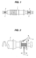
- the present invention relates to a rotor for a steam turbine and a method of manufacturing the same.
- Non-patent document No. 1 9 - 13% Cr heat resistance steels have excellent mechanical properties as a rotor material, the sliding characteristics are poor. It is reported that a destruction accident at a position between a journal part and a bearing metal tends to occur (Non-patent document No. 1).
- a cause of the damage in the journal is thought as the inclusion of a foreign matter between the journal and the bearing metal.
- the 9-13% Cr heat resistance steel has small thermal conductivity, local sticking may occur when the foreign matter enters.
- the amount of Cr is large, Cr carbides may be produced when temperature elevates at the time of the foreign matter enters so that the carbides become another foreign matter, which promotes further damage of the journal.
- the deposit welding layer is composed of upper and lower layers, in which the lower welding layer has a lower tensile strength and a larger coefficient of thermal expansion than those of the upper welding layer so that a residual stress remaining in the welding layers is made small (Patent document No. 2).
- the low alloy steel contains a smaller amount of Cr and has better sliding characteristics than the 9-13% Cr heat resisting steel, since the thermal expansion coefficient of the 9-13% Cr heat resisting steel is smaller than that of the low alloy steel, there remains a tensile residual stress in the surface of the deposit welding layer.
- a Cr content of the deposit welding layer increases due to dissolution of Cr (dilution) at welding from the base material, i.e. 9-13% Cr heat resting steel.
- the present invention was thus conceived to provide a steam turbine rotor made of 9-13% Cr heat resisting steel and a method of manufacturing the turbine rotor wherein the rotor with improved sliding characteristics, does not generate welding cracks and has no need of post heat treatment.
- the present invention is featured by a steam turbine rotor made of 9-13% Cr heat resisting steel wherein a coating of a low alloy steel containing Cr of 3wt% or less is formed on a sliding surface of the journal.
- the present invention is mainly featured by forming a coating layer of a low alloy steel being better in sliding characteristics than 9-13% Cr heat resisting steel, containing 3 wt% or less and an area rate of defects including voids and oxides in an arbitral cross-section thereof being 3 - 15%, on a sliding surface 3 of a journal 2 of a steam turbine rotor shaft 1 made of the 9 - 13% Cr heat resisting steel, by a method of high velocity flame spray method (HVOF; high velocity Oxy-Fuel).
- HVOF high velocity flame spray method
- the steam turbine rotor 1 of the present invention made of 9-13% Cr heat resisting steel is provided with the low alloy steel coating layer on the journal surface 3 in order to improve sliding characteristics of the journal surface 3 by the high velocity spray method, which is employed in place of the conventional deposit welding for forming the deposit welding layer on the journal surface 3.
- the steam turbine rotor made of the 9-13% Cr heat resisting steel hardly generates cracks in the low alloy steel coating layer and may eliminate post heat treatment.
- the thickness of the low alloy steel coating layer can be made thin, because there is no dilution of Cr from the base material.
- the purpose for improving the sliding characteristics of the journal of the steam turbine rotor made of the 9-13% Cr heat resisting steel was realized by the high velocity flame spray method with a low thermal energy thereby to achieve high reliability in a simple way, compared with the conventional deposit welding method.
- the method of the present invention may eliminate the cracks in the coating and post heat treatment.
- the steam turbine rotor made of the 9-13% Cr heat resisting steel is provided with the low alloy steel coating layer formed on the surface of the journal so that the sliding characteristics are remarkably improved.
- the low alloy steels utilized in the present invention contains preferably 3wt% or less of Cr. A reason for that if the amount of Cr exceeded 3 wt%, the sliding characteristics may be degraded to reduce a thermal conductivity.
- low alloy steel containing 0.5 to 2.5% of Cr - 0.4 to 1.1% of Mo, the balance being Fe or a low alloy steel containing 2.0 to 2.5% of Cr, 0.9 to 1,1% of Mo - 0.3% or less of V, the balance being Fe.
- These low alloy steels have balanced coating strength and sliding characteristics, but the coating material is not limited to the above steels. Persons skilled in the art may select other appropriate materials based on their experience and knowledge.
- a thickness of the coating of the low alloy steel is preferably 0.5 to 5mm. The reason for that is that if the thickness were less than 0. 5mm, the surface of the 9-13% Cr heat resisting steel may be exposed within a short period of time when a foreign matter, etc is included in the sliding portions, and the coating is subjected to abrasion. This is a problem for achieving the long service life of the rotor shaft.
- the compression residual stress which is an advantage of the high velocity flame spray method decreases gradually, cracks or peeling off of the coating may take place in the coating.
- the thickness of the spray coating itself is an effective coating thickness because there is no influence by the dilution of Cr from the base material, which was observed in the conventional deposit welding method, effects of the coating are achieved by a 1/2 or less thickness of the conventional deposit welding coating. Accordingly, it is not economical to form an excessively thick coating, because it tales a long time to perform the process.
- the low alloy steel coating layer should preferably contain defects including pores and oxides in an area rate in an arbitral cross section should preferably be 3 to 15%.
- Fig. 3 shows an example of a microscopic photograph of the low alloy steel.
- the coating 5 having a thickness of about 1. 5mm, which is made of the low alloy steel coating is formed on the base material 4 of the 9-13% Cr heat resisting steel.
- Black network patterns are found in the low alloying element coating 5 in the sectional structure photograph.
- the patterns are of defects formed in the spray coating layer, the defects being pores and/or oxides (Fe oxides, small amounts of alloying element oxides other than Fe) formed on the surface of the powder of the low alloy steel during that the powder particles fly in the high velocity flame when the low alloy steel layer 5 is formed by the high velocity flame spray coating method.
- the area rate of the defects (the network patterns) in the sectional area of the coating was measured by an image analysis to be about 10%.
- these defects including oxides and pores function as fine pores in the coating, they store a lubricant therein. As a result, the coating hardly generates lubricant loss and prevents sticking.
- the lubricant holding effect is insufficient if the defect rate is less than 3%, but if the defect rate exceeds 15%, reduction in strength of the coating layer takes place.
- strength of the coating layer depends on a status or distribution structure of the defects. Even if the defect rate is the same, strength of the coating is higher if fine defects are homogeneously dispersed than the case where coarse defects are partially or locally deposit. Thus, the strength of 40MPa or more is preferable. If the strength is less than 40MPa, peeling-off of the inner destruction of the coating layer tend to take place.
- the most preferable coating layer of the low alloy steel for the steam turbine rotor made of the 9-13% Cr heat resisting steel should have a Cr content of 3% by weight or les, a thickness of 0.5 to 5mm, the area rate of defects including pores and oxides in an arbitral sectional structure is 3 to 15%, and a peeling-strength is 40MPa or more.
- the high velocity flame spray coating method is most preferable for forming the above-described coating layer.
- material such as a plasma spray coating method, flame spray coating method, arc spray coating method, etc
- material is melted at high temperature and sprayed to rapidly quench and solidify the sprayed material thereby to form a coating layer.
- the high velocity flame spray coating method powder is sprayed at a high velocity to form a coating layer by utilizing plastic deformation of the base material and powder at collision caused by dynamic energy of the powder.
- the coating layer of the high velocity spray coating is excellent in adhesion strength and strength of the coating, and hardly generates cracks and peeling-off.
- Fig. 4 shows a schematic view of a sliding testing device for evaluation of the low alloying element coating layer.
- the device has a sliding testing section constituted by a testing journal 25 disposed at one end of a shaft 23 supported pivotally on two rolling bearing 22 and a sliding bearing.
- Lubricant is supplied from a lubricant supply mechanism (not shown) to the sliding bearing 24.
- the sliding bearing 24 is fixed on a base 26, which is capable of up and down movement.
- the other end of the shaft 23 is connected to a rotary shaft 21 of an electric rotating machine (not shown), thereby to rotate the shaft 23 of the electric rotating machine.
- the bearing test is carried out wherein the device imparts a suitable surface pressure to a sliding face between the test journal 25 and the sliding bearing 24 by lifting the base 25.
- a low alloy steel coating 5 was formed on the test journal of a rotor shaft made of 12% Cr heat resisting steel having a composition of 11% of Cr - 2.6% of W- 0,2% of Mo- 2.5% of Co - 0.5% of Ni - 0.5% of Mn - 0.2% of V - 0.05% of Si - 0.1% of C - 0.1% of Nb- 0.03% of N - 0.02% of B, the balance being Fe.
- a groove having a depth 32 of 2mm was formed in the test journal 25. Both ends of the groove had an inclined angle 33 of 30°.
- the purpose of forming the inclined groove walls is to prevent defects formed between the spray coating layer and the base material at the ends of the groove thereby preventing lowering of adhesion.
- the groove angle 33 is preferably within a range of 15 to 45° .
- the numeral 31 denotes a shaft diameter.
- the surface including the groove to be treated was subjected to de-fatting treatment, followed by surface-roughening treatment by a blasting treatment using alumina grid. Thereafter, The spray powder of a low alloy steel having a composition of 1.3% of Cr - 0.5% of Mo- the balance being Fe and having a particle size of 25 to 63 ⁇ m was sprayed with a HVOF apparatus (manufactured by TAFA) on the surface of the 12% Cr mother material.
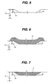
- the resulting coating layer 5 had a thickness of about 1 mm larger than the groove depth 33, as shown in Fig. 6 .
- the numeral 31 denotes a shaft diameter and 33 an inclined angle.
- a cross sectional structure of the low alloy steel coating layer on the 12% Cr heat resisting steel obtained in substantially the same conditions as above was observed and the defect rate was measured by the image analysis.
- the area rate of the defects was about 10%.
- the tensile adhesion strength was measured. As a result, a value was not measured because breakage took place at the adhesive, but the adhesion strength should be 70MPa or higher because the strength of the adhesive was about 70MPa.
- the spray coating was finished by machining and polishing to be a predetermined diameter 31.
- the numeral 5 denotes the low alloy steel coating layer, numeral 32 a depth of the groove, and numeral 33 an inclination angle.
- the 12% Cr heat resisting steel shaft 23 having the low alloying element coating layer 5 on the journal 25 was installed in the testing apparatus shown in Fig. 4 to conduct the bearing test.
- the test conditions were as follows.
- the shaft was rotated at a circumferential speed of 50m/sec under a bearing load of 30kg/cm 2 , iron powder having a particle size of 125 to 300 ⁇ m was added as a foreign matter to a lubricant at a rate of about 1g/min for ten minutes so as to investigate damage of the shafts and bearings.
- temperatures of the bearing metals in the tests were measured. When lubrication is degraded by lubricant loss between the shaft and the bearing metal, which may be caused by inclusion of the foreign matter, the temperature elevates by friction between the metals. The lower the temperature rise of the bearing metal, the better the sliding characteristics are achieved.
- Fig. 8 shows a temperature change of the bearing metal during the test.
- the test of the 12% Cr heat resisting steel shaft provided with the low alloy steel coating layer showed a sudden temperature rise after inclusion of the foreign matter was observed, but it lowered within a short period of time. The temperature in the stable period was reached about 80°C.
- the conventional deposit welding layer was formed on the journal of the 12% Cr heat resisting steel, after the foreign matter inclusion, the sudden temperature rise was observed for a while and lowered within a short period of time as same as in the shaft of the present invention.
- the rotor made of the 12% Cr heat resisting steel having the low alloy steel coating layer exhibited remarkably improved bearing characteristics, compared with the 12% Cr heat resisting steel shaft having no low alloy steel coating layer. Further, it was revealed that the bearing characteristics of the shaft of the present invention were superior to the conventional deposit welding coating layer.
- Fig. 9 shows a schematic cross sectional view of a high pressure stem turbine comprising a turbine rotor shaft 48 made of 12% Cr heat resisting steel (11% of Cr - 2.6% of W - 0.2% of Mo - 2.5% of Co - 0.5% of Ni - 0.5% of Mn - 0.2% V - 0.05% of Si - 0.1% of C - 0.01% of Nb - 0.03% of N - 0.02% of B -the balance being Fe), a high pressure partition plate 44 , a high pressure blade 45, a high pressure inner nozzle 46, a high pressure outer nozzle 47, a main stem entrance port 49, a steam discharge port 50, etc.
- the low alloy steel coating layers of the present invention were applied to sliding sections of a first bearing 41, second bearing 42 and thrust bearing 43 disposed to the turbine rotor shaft 48.
- the process of forming the coating layer was the same as in Example 1. At first, a groove was formed having a depth of 3mm prior to the process. Both ends of the beveling had inclination angle of 30°. Next, the surface including the groove to be processed was subjected to de-fatting, followed by roughening treatment by blasting with alumina grid. Thereafter, the low alloy steel coating layer was formed using spray powder of the low alloying element powder (1.3% of Cr - 0.5% of Mo - the balance being Fe) on the surface having a thickness of about 1mm larger than the depth of the groove by means of the JP5000 type HVOF apparatus (manufactured by TAFA).
- the high pressure steam turbine that utilized the turbine rotor shaft 48 having the sliding bearing to which the low alloy steel coating layer was applied was operated from one year.
- the sliding bearing of the turbine rotor shaft 48 of the high pressure steam turbine was inspected after the one year operation. It was found that the sliding bearing and the bearing metal were both sound.
- the present invention can improve durability of the bearing of the steam turbine rotor shaft.
Landscapes
- Chemical & Material Sciences (AREA)
- Engineering & Computer Science (AREA)
- Mechanical Engineering (AREA)
- Materials Engineering (AREA)
- Metallurgy (AREA)
- Organic Chemistry (AREA)
- Chemical Kinetics & Catalysis (AREA)
- Physics & Mathematics (AREA)
- Plasma & Fusion (AREA)
- General Engineering & Computer Science (AREA)
- Coating By Spraying Or Casting (AREA)
- Turbine Rotor Nozzle Sealing (AREA)
Applications Claiming Priority (2)
| Application Number | Priority Date | Filing Date | Title |
|---|---|---|---|
| JP2005177112 | 2005-06-17 | ||
| PCT/JP2006/311577 WO2006134831A1 (ja) | 2005-06-17 | 2006-06-09 | 蒸気タービン用ロータとその製造方法 |
Publications (4)
| Publication Number | Publication Date |
|---|---|
| EP1898048A1 true EP1898048A1 (de) | 2008-03-12 |
| EP1898048A8 EP1898048A8 (de) | 2008-05-14 |
| EP1898048A4 EP1898048A4 (de) | 2009-12-02 |
| EP1898048B1 EP1898048B1 (de) | 2011-03-09 |
Family
ID=37532194
Family Applications (1)
| Application Number | Title | Priority Date | Filing Date |
|---|---|---|---|
| EP06757200A Revoked EP1898048B1 (de) | 2005-06-17 | 2006-06-09 | Rotor für dampfturbine und verfahren zu dessen herstellung |
Country Status (6)
| Country | Link |
|---|---|
| US (1) | US8485788B2 (de) |
| EP (1) | EP1898048B1 (de) |
| JP (1) | JP4584999B2 (de) |
| CN (1) | CN101198768B (de) |
| DE (1) | DE602006020567D1 (de) |
| WO (1) | WO2006134831A1 (de) |
Cited By (5)
| Publication number | Priority date | Publication date | Assignee | Title |
|---|---|---|---|---|
| EP2108476A1 (de) * | 2008-04-09 | 2009-10-14 | Siemens Aktiengesellschaft | Verfahren zur Beschichtung eines metallischen Substrats mit einer Schicht aus niedrig legiertem Stahl |
| DE102009039824A1 (de) * | 2009-09-02 | 2011-03-03 | Siemens Aktiengesellschaft | Rotorwelle für eine Dampfturbine |
| EP2444516A1 (de) * | 2010-10-25 | 2012-04-25 | United Technologies Corporation | Thermisches Aufspritzbeschichtungsverfahren für Verdichterwellen |
| EP3015644A1 (de) * | 2014-10-29 | 2016-05-04 | Alstom Technology Limited | Dampfturbinenrotor |
| EP3199659A1 (de) * | 2016-01-28 | 2017-08-02 | Rolls-Royce plc | Verfahren zur herstellung eines zylindrischen hochtemperaturbauteils für einen gasturbinenmotor |
Families Citing this family (9)
| Publication number | Priority date | Publication date | Assignee | Title |
|---|---|---|---|---|
| ATE544704T1 (de) * | 2008-07-14 | 2012-02-15 | Sulzer Metco Coatings Gmbh | Tauchbadrolle und verfahren zum herstellen einer tauchbadrolle |
| JP5355343B2 (ja) * | 2009-10-15 | 2013-11-27 | 株式会社東芝 | タービン装置補修方法 |
| JP5578893B2 (ja) * | 2010-03-12 | 2014-08-27 | 株式会社日立製作所 | 蒸気タービンの摺動部を有する部材 |
| US8961144B2 (en) * | 2011-06-30 | 2015-02-24 | General Electric Company | Turbine disk preform, welded turbine rotor made therewith and methods of making the same |
| EP2821772A4 (de) * | 2012-02-29 | 2015-10-21 | Nsk Ltd | Verfahren zur bewertung der festigkeit eines gussprodukts und gussprodukt |
| WO2013130169A1 (en) * | 2012-02-29 | 2013-09-06 | Chevron U.S.A. Inc. | Coating compositions, applications thereof, and methods of forming |
| US9316341B2 (en) | 2012-02-29 | 2016-04-19 | Chevron U.S.A. Inc. | Coating compositions, applications thereof, and methods of forming |
| EP2767616A1 (de) | 2013-02-15 | 2014-08-20 | Alstom Technology Ltd | Turbomaschinenkomponente mit einem erosions- und korrosionsbeständigen Beschichtungssystem und Verfahren zur Herstellung solch einer Komponente |
| CN110230050A (zh) * | 2019-04-25 | 2019-09-13 | 浙江工业大学 | 一种激光熔覆用铁基合金粉末及其制备方法与应用 |
Family Cites Families (12)
| Publication number | Priority date | Publication date | Assignee | Title |
|---|---|---|---|---|
| JPS57137456A (en) * | 1981-02-19 | 1982-08-25 | Toshiba Corp | Turbine rotor |
| JPS57165603A (en) | 1981-04-03 | 1982-10-12 | Hitachi Ltd | Rotor shaft for steam turbine |
| JPS61112702A (ja) | 1984-11-06 | 1986-05-30 | Fuji Electric Co Ltd | 蒸気タ−ビンロ−タの被覆層形成方法 |
| JPH06272503A (ja) | 1993-03-17 | 1994-09-27 | Japan Steel Works Ltd:The | 5〜13%Cr系タービンロータ及び該ロータジャーナル部の肉盛溶接方法 |
| DE4442186C2 (de) * | 1994-11-26 | 1999-03-04 | Glyco Metall Werke | Schichtwerkstoff und Verfahren zu seiner Herstellung |
| JP3911730B2 (ja) * | 1995-09-20 | 2007-05-09 | 株式会社日立プラントテクノロジー | ポンプ及びその製造方法 |
| US6190124B1 (en) * | 1997-11-26 | 2001-02-20 | United Technologies Corporation | Columnar zirconium oxide abrasive coating for a gas turbine engine seal system |
| JP3793667B2 (ja) * | 1999-07-09 | 2006-07-05 | 株式会社日立製作所 | 低圧蒸気タービン最終段動翼の製造方法 |
| US6234755B1 (en) * | 1999-10-04 | 2001-05-22 | General Electric Company | Method for improving the cooling effectiveness of a gaseous coolant stream, and related articles of manufacture |
| JP4199500B2 (ja) | 2002-09-12 | 2008-12-17 | トヨタ自動車株式会社 | シリンダブロック |
| JP4000075B2 (ja) * | 2003-02-27 | 2007-10-31 | 株式会社東芝 | ロータの補修方法 |
| EP1798302A4 (de) | 2004-08-23 | 2009-12-02 | Toshiba Kk | Verfahren und vorrichtung zur reparatur eines rotors |
-
2006
- 2006-06-09 EP EP06757200A patent/EP1898048B1/de not_active Revoked
- 2006-06-09 DE DE602006020567T patent/DE602006020567D1/de active Active
- 2006-06-09 WO PCT/JP2006/311577 patent/WO2006134831A1/ja not_active Ceased
- 2006-06-09 CN CN2006800212776A patent/CN101198768B/zh not_active Expired - Fee Related
- 2006-06-09 JP JP2007521261A patent/JP4584999B2/ja not_active Expired - Fee Related
- 2006-06-09 US US11/917,547 patent/US8485788B2/en not_active Expired - Fee Related
Cited By (10)
| Publication number | Priority date | Publication date | Assignee | Title |
|---|---|---|---|---|
| EP2108476A1 (de) * | 2008-04-09 | 2009-10-14 | Siemens Aktiengesellschaft | Verfahren zur Beschichtung eines metallischen Substrats mit einer Schicht aus niedrig legiertem Stahl |
| DE102009039824A1 (de) * | 2009-09-02 | 2011-03-03 | Siemens Aktiengesellschaft | Rotorwelle für eine Dampfturbine |
| DE102009039824A8 (de) * | 2009-09-02 | 2011-06-01 | Siemens Aktiengesellschaft | Rotorwelle für eine Dampfturbine |
| WO2011026715A3 (de) * | 2009-09-02 | 2011-10-20 | Siemens Aktiengesellschaft | Rotorwelle für eine dampfturbine |
| DE102009039824B4 (de) * | 2009-09-02 | 2014-10-16 | Siemens Aktiengesellschaft | Rotorwelle für eine Dampfturbine |
| EP2444516A1 (de) * | 2010-10-25 | 2012-04-25 | United Technologies Corporation | Thermisches Aufspritzbeschichtungsverfahren für Verdichterwellen |
| EP3015644A1 (de) * | 2014-10-29 | 2016-05-04 | Alstom Technology Limited | Dampfturbinenrotor |
| US10533421B2 (en) | 2014-10-29 | 2020-01-14 | General Electric Technology Gmbh | Steam turbine rotor |
| US11053799B2 (en) | 2014-10-29 | 2021-07-06 | General Electric Technology Gmbh | Steam turbine rotor |
| EP3199659A1 (de) * | 2016-01-28 | 2017-08-02 | Rolls-Royce plc | Verfahren zur herstellung eines zylindrischen hochtemperaturbauteils für einen gasturbinenmotor |
Also Published As
| Publication number | Publication date |
|---|---|
| JPWO2006134831A1 (ja) | 2009-01-08 |
| US20090311103A1 (en) | 2009-12-17 |
| US8485788B2 (en) | 2013-07-16 |
| EP1898048B1 (de) | 2011-03-09 |
| JP4584999B2 (ja) | 2010-11-24 |
| CN101198768B (zh) | 2011-12-28 |
| DE602006020567D1 (de) | 2011-04-21 |
| CN101198768A (zh) | 2008-06-11 |
| EP1898048A8 (de) | 2008-05-14 |
| WO2006134831A1 (ja) | 2006-12-21 |
| EP1898048A4 (de) | 2009-12-02 |
Similar Documents
| Publication | Publication Date | Title |
|---|---|---|
| EP1898048B1 (de) | Rotor für dampfturbine und verfahren zu dessen herstellung | |
| CA2653070C (en) | Thermal spray coated work rolls | |
| Jafarlou et al. | Influence of cold sprayed Cr3C2-Ni coating on fracture characteristics of additively manufactured 15Cr-5Ni stainless steel | |
| Zhang et al. | High performance tin-based Babbitt coatings deposited by high-pressure cold spraying | |
| Hajare et al. | Comparative study of wear behaviour of Thermal Spray HVOF coating on 304 SS | |
| Swain et al. | Investigation of tribological behavior of plasma sprayed NiTi coating for aerospace application | |
| Liu et al. | Feasibility exploration of superalloys for AISI 4140 steel repairing using laser engineered net shaping | |
| US20060260125A1 (en) | Method for repairing a gas turbine engine airfoil part using a kinetic metallization process | |
| Amanov | Surface engineering-controlled tribological behavior and adhesion strength of Ni-Cr coating sprayed onto carburized AISI 4340 steel substrate | |
| Chang et al. | Effect of heat treatment on residual stress and wear resistance of CX stainless steel manufactured by Selective Laser Melting | |
| Verwimp et al. | Applications of laser cladded WC-based wear resistant coatings | |
| US20050152805A1 (en) | Method for forming a wear-resistant hard-face contact area on a workpiece, such as a gas turbine engine part | |
| US20060039788A1 (en) | Hardface alloy | |
| Mohassel et al. | Effect of shot peening on tribological behaviors of molybdenum-thermal spray coating using HVOF method | |
| Rodriguez et al. | Heat treated twin wire arc spray AISI 420 coatings under dry and wet abrasive wear | |
| Singh et al. | A REVIEW ON THE ROLE OF BURNISHING TECHNIQUES ON COMBATING SOLID PARTICLE EROSION OF THERMAL SPRAY COATINGS | |
| Rakhadilov et al. | Study of compressed air pressure on the properties of coatings obtained by supersonic metallization | |
| Zhang et al. | The characterization of soft antifriction coating on the tin bronze by electro-spark alloying | |
| Panwariya et al. | Evaluation of hardness and wear resistance of nitride layer on Ti-6Al-4V titanium alloy by tungsten inert gas (TIG) melting process | |
| Zhao et al. | Effect of rolling process on microstructure and wear properties of high carbon equivalent gray cast iron | |
| RU2826632C1 (ru) | Способ получения износостойкого антифрикционного покрытия на подложке из стали, никелевого или титанового сплава | |
| Idir et al. | Study of wear resistance in dry and lubricated regime of molybdenum coating obtained by thermal spraying | |
| Lehtovaara et al. | FRETTING BEHAVIOUR OF THERMAL SPRAYED HARDMETAL COATINGS AGAINST QUENCHED AND TEMPERED STEEL | |
| Nagabhushana et al. | Erosion studies of plasma-sprayed NiCrBSi, Mo and flyash cenosphere coating | |
| Qi et al. | Abrasive wear mechanisms of VPS‐and HVOF‐sprayed TiC‐Ni based nanocrystalline coatings |
Legal Events
| Date | Code | Title | Description |
|---|---|---|---|
| PUAI | Public reference made under article 153(3) epc to a published international application that has entered the european phase |
Free format text: ORIGINAL CODE: 0009012 |
|
| 17P | Request for examination filed |
Effective date: 20080117 |
|
| AK | Designated contracting states |
Kind code of ref document: A1 Designated state(s): AT BE BG CH CY CZ DE DK EE ES FI FR GB GR HU IE IS IT LI LT LU LV MC NL PL PT RO SE SI SK TR |
|
| RBV | Designated contracting states (corrected) |
Designated state(s): DE FR GB |
|
| DAX | Request for extension of the european patent (deleted) | ||
| RIN1 | Information on inventor provided before grant (corrected) |
Inventor name: MEBATA, AKIRAC/O HITACHI, LTD., INTELLECTUAL PROPE Inventor name: ARAI, MASAHIKOC/O HITACHI, LTD., INTELLECTUAL PROP Inventor name: KOJIMA, YOSHITAKAC/O HITACHI, LTD., INTELLECTUAL P Inventor name: ARIKAWA, HIDEYUKIC/O HITACHI, LTD., INTELLECTUAL P Inventor name: TORIYA, HAJIMEC/O HITACHI, LTD., INTELLECTUAL PROP |
|
| RBV | Designated contracting states (corrected) |
Designated state(s): DE FR GB |
|
| DAX | Request for extension of the european patent (deleted) | ||
| A4 | Supplementary search report drawn up and despatched |
Effective date: 20091104 |
|
| RIC1 | Information provided on ipc code assigned before grant |
Ipc: C23C 4/12 20060101ALI20091029BHEP Ipc: F01D 25/00 20060101ALI20091029BHEP Ipc: F01D 5/06 20060101ALI20091029BHEP Ipc: C22C 38/24 20060101ALI20091029BHEP Ipc: C22C 38/00 20060101ALI20091029BHEP Ipc: C22C 38/18 20060101ALI20091029BHEP Ipc: F01D 5/02 20060101AFI20070208BHEP Ipc: C23C 4/08 20060101ALI20091029BHEP Ipc: C23C 4/18 20060101ALI20091029BHEP |
|
| 17Q | First examination report despatched |
Effective date: 20100119 |
|
| GRAP | Despatch of communication of intention to grant a patent |
Free format text: ORIGINAL CODE: EPIDOSNIGR1 |
|
| GRAS | Grant fee paid |
Free format text: ORIGINAL CODE: EPIDOSNIGR3 |
|
| GRAA | (expected) grant |
Free format text: ORIGINAL CODE: 0009210 |
|
| AK | Designated contracting states |
Kind code of ref document: B1 Designated state(s): DE FR GB |
|
| REG | Reference to a national code |
Ref country code: GB Ref legal event code: FG4D |
|
| REF | Corresponds to: |
Ref document number: 602006020567 Country of ref document: DE Date of ref document: 20110421 Kind code of ref document: P |
|
| REG | Reference to a national code |
Ref country code: DE Ref legal event code: R096 Ref document number: 602006020567 Country of ref document: DE Effective date: 20110421 |
|
| PLBI | Opposition filed |
Free format text: ORIGINAL CODE: 0009260 |
|
| PLAX | Notice of opposition and request to file observation + time limit sent |
Free format text: ORIGINAL CODE: EPIDOSNOBS2 |
|
| 26 | Opposition filed |
Opponent name: SIEMENS AG Effective date: 20111207 |
|
| PLAB | Opposition data, opponent's data or that of the opponent's representative modified |
Free format text: ORIGINAL CODE: 0009299OPPO |
|
| R26 | Opposition filed (corrected) |
Opponent name: SIEMENS AG Effective date: 20111207 |
|
| REG | Reference to a national code |
Ref country code: DE Ref legal event code: R026 Ref document number: 602006020567 Country of ref document: DE Effective date: 20111207 |
|
| PLAF | Information modified related to communication of a notice of opposition and request to file observations + time limit |
Free format text: ORIGINAL CODE: EPIDOSCOBS2 |
|
| PLBB | Reply of patent proprietor to notice(s) of opposition received |
Free format text: ORIGINAL CODE: EPIDOSNOBS3 |
|
| RAP2 | Party data changed (patent owner data changed or rights of a patent transferred) |
Owner name: MITSUBISHI HITACHI POWER SYSTEMS, LTD. |
|
| REG | Reference to a national code |
Ref country code: DE Ref legal event code: R082 Ref document number: 602006020567 Country of ref document: DE Representative=s name: MERH-IP MATIAS ERNY REICHL HOFFMANN, DE |
|
| REG | Reference to a national code |
Ref country code: DE Ref legal event code: R082 Ref document number: 602006020567 Country of ref document: DE Representative=s name: MERH-IP MATIAS ERNY REICHL HOFFMANN, DE Effective date: 20140716 Ref country code: DE Ref legal event code: R081 Ref document number: 602006020567 Country of ref document: DE Owner name: MITSUBISHI HITACHI POWER SYSTEMS, LTD., YOKOHA, JP Free format text: FORMER OWNER: HITACHI, LTD., TOKYO, JP Effective date: 20140716 Ref country code: DE Ref legal event code: R082 Ref document number: 602006020567 Country of ref document: DE Representative=s name: MERH-IP MATIAS ERNY REICHL HOFFMANN PATENTANWA, DE Effective date: 20140716 |
|
| APAH | Appeal reference modified |
Free format text: ORIGINAL CODE: EPIDOSCREFNO |
|
| APBM | Appeal reference recorded |
Free format text: ORIGINAL CODE: EPIDOSNREFNO |
|
| APBP | Date of receipt of notice of appeal recorded |
Free format text: ORIGINAL CODE: EPIDOSNNOA2O |
|
| APBM | Appeal reference recorded |
Free format text: ORIGINAL CODE: EPIDOSNREFNO |
|
| APBP | Date of receipt of notice of appeal recorded |
Free format text: ORIGINAL CODE: EPIDOSNNOA2O |
|
| APBQ | Date of receipt of statement of grounds of appeal recorded |
Free format text: ORIGINAL CODE: EPIDOSNNOA3O |
|
| APBQ | Date of receipt of statement of grounds of appeal recorded |
Free format text: ORIGINAL CODE: EPIDOSNNOA3O |
|
| RAP2 | Party data changed (patent owner data changed or rights of a patent transferred) |
Owner name: MITSUBISHI HITACHI POWER SYSTEMS, LTD. |
|
| REG | Reference to a national code |
Ref country code: GB Ref legal event code: 732E Free format text: REGISTERED BETWEEN 20150528 AND 20150603 |
|
| REG | Reference to a national code |
Ref country code: FR Ref legal event code: PLFP Year of fee payment: 11 |
|
| REG | Reference to a national code |
Ref country code: FR Ref legal event code: PLFP Year of fee payment: 12 |
|
| PLAB | Opposition data, opponent's data or that of the opponent's representative modified |
Free format text: ORIGINAL CODE: 0009299OPPO |
|
| R26 | Opposition filed (corrected) |
Opponent name: SIEMENS AKTIENGESELLSCHAFT Effective date: 20111207 |
|
| REG | Reference to a national code |
Ref country code: FR Ref legal event code: PLFP Year of fee payment: 13 |
|
| APBU | Appeal procedure closed |
Free format text: ORIGINAL CODE: EPIDOSNNOA9O |
|
| REG | Reference to a national code |
Ref country code: DE Ref legal event code: R082 Ref document number: 602006020567 Country of ref document: DE Representative=s name: MERH-IP MATIAS ERNY REICHL HOFFMANN PATENTANWA, DE Ref country code: DE Ref legal event code: R081 Ref document number: 602006020567 Country of ref document: DE Owner name: MITSUBISHI POWER, LTD., JP Free format text: FORMER OWNER: MITSUBISHI HITACHI POWER SYSTEMS, LTD., YOKOHAMA-SHI, KANAGAWA, JP |
|
| PGFP | Annual fee paid to national office [announced via postgrant information from national office to epo] |
Ref country code: DE Payment date: 20210511 Year of fee payment: 16 Ref country code: FR Payment date: 20210513 Year of fee payment: 16 |
|
| PGFP | Annual fee paid to national office [announced via postgrant information from national office to epo] |
Ref country code: GB Payment date: 20210512 Year of fee payment: 16 |
|
| REG | Reference to a national code |
Ref country code: DE Ref legal event code: R119 Ref document number: 602006020567 Country of ref document: DE |
|
| GBPC | Gb: european patent ceased through non-payment of renewal fee |
Effective date: 20220609 |
|
| PG25 | Lapsed in a contracting state [announced via postgrant information from national office to epo] |
Ref country code: FR Free format text: LAPSE BECAUSE OF NON-PAYMENT OF DUE FEES Effective date: 20220630 |
|
| PG25 | Lapsed in a contracting state [announced via postgrant information from national office to epo] |
Ref country code: GB Free format text: LAPSE BECAUSE OF NON-PAYMENT OF DUE FEES Effective date: 20220609 Ref country code: DE Free format text: LAPSE BECAUSE OF NON-PAYMENT OF DUE FEES Effective date: 20230103 |
|
| RDAF | Communication despatched that patent is revoked |
Free format text: ORIGINAL CODE: EPIDOSNREV1 |
|
| STAA | Information on the status of an ep patent application or granted ep patent |
Free format text: STATUS: THE PATENT HAS BEEN GRANTED |
|
| REG | Reference to a national code |
Ref country code: DE Ref legal event code: R103 Ref document number: 602006020567 Country of ref document: DE Ref country code: DE Ref legal event code: R064 Ref document number: 602006020567 Country of ref document: DE |
|
| RDAG | Patent revoked |
Free format text: ORIGINAL CODE: 0009271 |
|
| STAA | Information on the status of an ep patent application or granted ep patent |
Free format text: STATUS: PATENT REVOKED |
|
| 27W | Patent revoked |
Effective date: 20240508 |