EP1898070A2 - Système et appareil pour enfermer un équipement - Google Patents
Système et appareil pour enfermer un équipement Download PDFInfo
- Publication number
- EP1898070A2 EP1898070A2 EP07106553A EP07106553A EP1898070A2 EP 1898070 A2 EP1898070 A2 EP 1898070A2 EP 07106553 A EP07106553 A EP 07106553A EP 07106553 A EP07106553 A EP 07106553A EP 1898070 A2 EP1898070 A2 EP 1898070A2
- Authority
- EP
- European Patent Office
- Prior art keywords
- enclosure
- disposed
- equipment
- ventilation ports
- baffle
- Prior art date
- Legal status (The legal status is an assumption and is not a legal conclusion. Google has not performed a legal analysis and makes no representation as to the accuracy of the status listed.)
- Withdrawn
Links
Images


Classifications
-
- F—MECHANICAL ENGINEERING; LIGHTING; HEATING; WEAPONS; BLASTING
- F01—MACHINES OR ENGINES IN GENERAL; ENGINE PLANTS IN GENERAL; STEAM ENGINES
- F01D—NON-POSITIVE DISPLACEMENT MACHINES OR ENGINES, e.g. STEAM TURBINES
- F01D25/00—Component parts, details, or accessories, not provided for in, or of interest apart from, other groups
- F01D25/08—Cooling; Heating; Heat-insulation
- F01D25/14—Casings modified therefor
Definitions
- the present disclosure relates generally to equipment enclosures, and particularly to enclosures surrounding power plant equipment.
- Power generating equipment such as gas turbines for example, may create significant amounts of acoustic energy (noise) during operation. Therefore it is common practice, as may be required by national agencies or the power station operators, to enclose such equipment within sound enclosures to dampen, or prevent transmission of, this acoustic energy into the surrounding environment. In addition to acoustic energy, many types of power generating equipment also generate large quantities of heat. When this equipment is sited indoors, a means to dissipate the heat to the exterior of the building and maintain specific thermal operating conditions may be required.
- enclosures utilize blowers to force cooling air through the enclosures to remove the heat generated by the equipment contained therein. Often, these are large blowers that may utilize motors from twenty to forty horsepower in size. These blowers may consume significant energy and require regular repair and maintenance, which may have a negative impact on the uptime of the generating equipment. Accordingly, there is a need in the art for an equipment enclosure arrangement that overcomes these drawbacks.
- An embodiment of the invention includes an enclosure having a top and at least one side to surround equipment.
- a first set of ventilation ports is disposed toward the bottom of the enclosure, a second set of ventilation ports is disposed toward the top of the enclosure, and a baffle is disposed proximate the top at the interior of the enclosure.
- the top of the opening of the first set of ventilation ports is disposed to be lower than the bottom of the equipment, the bottom of the opening of the second set of ventilation ports is disposed to be higher than the top of the equipment, and the baffle is configured to direct a cooling medium toward the second set of ventilation ports.
- the generating equipment includes a generator, which is mechanically driven by a gas turbine or a steam turbine.
- the gas turbine comprises an inlet plenum, and an exhaust diffuser.
- the power plant system includes an enclosure enclosing at least one of the generator, the gas turbine, the steam turbine, the inlet plenum, and the exhaust diffuser, or any combination of the foregoing.
- the enclosure includes a top and at least one side to surround the equipment.
- a first set of ventilation ports is disposed toward the bottom of the enclosure, a second set of ventilation ports is disposed toward the top of the enclosure, and a baffle is disposed toward the top at the interior of the enclosure.
- the top of the opening of the first set of ventilation ports is disposed to be lower than the bottom of the equipment, the bottom of the opening of the second set of ventilation ports is disposed to be higher than the top of the equipment, and the baffle is configured to direct a cooling medium toward the second set of ventilation ports.
- An embodiment of the invention provides a naturally ventilated power plant equipment enclosure, employing natural convection as opposed to forced convection.
- the enclosure is designed to limit the transmission of acoustic energy generated by the equipment, while maintaining appropriate thermal conditions for operation of the equipment.
- the enclosure includes ventilation inlets near the enclosure bottom and ventilation outlets near the enclosure top.
- the inlets may be located on or near the floor or at or near the bottom of the enclosure sidewalls.
- the outlets may be positioned on the enclosure roof or near the top of the enclosure sidewalls.
- outlets may be located on the top of a pitched roof to drive maximum buoyancy flow through the enclosure. If outlets are not disposed on the enclosure top, due to an obstruction for example, or for reasons relating to the desire to use the enclosure top as a storage area, for example, ventilation outlets may be positioned on the enclosure sidewalls.
- Baffles or any airflow management member suitable for directing a cooling medium, such as air, may be used to increase buoyancy flow, divert the ventilation airflow, and improve natural ventilation through the enclosure to uniformly cool the equipment. Baffle quantity and arrangement will depend on the number and location of outlets.
- the exemplary power plant 50 may include an exhaust enclosure 55 to enclose a gas turbine exhaust diffuser, a gas turbine enclosure 60 to enclose a gas turbine and associated piping, an inlet plenum barrier 65 to enclose a gas turbine inlet and load compartment, a generator barrier 70 to enclose a generator, and a steam turbine enclosure 75 to enclose a steam turbine and associated piping.
- reference numeral 75 may also be used to represent additional enclosures not depicted in Figure 1, to enclose equipment such as high pressure valves, fuel gas supply systems, and compressors, for example.
- FIG. 1 an embodiment of an exemplary equipment enclosure 100 is depicted.
- reference numeral 100 will refer to an equipment enclosure in general, and it will be appreciated that the enclosure 100 may be any of the enclosures 55, 60, 65, 70, 75 utilized within the power plant 50.
- a plurality of surfaces (also herein referred to as sides) 105 and a top 110 surround power plant equipment (not visible in Figure 2) to reduce the transmission of acoustic energy (noise) that is created by operation of the equipment.
- An exemplary gas turbine exhaust diffuser 140 disposed within the enclosure 100 is depicted.
- An access port 142 allows connection of the equipment to adjoining power generation equipment as necessary.
- a first set of ventilation ports (also referred to herein as inlets) 115 and a second set of ventilation ports (also referred to herein as outlets) 120 allow for the flow of a cooling medium, such as air, within the enclosure 100 to carry away heat that is generated by operation of the equipment.
- the inlets 115 are disposed on sides 105 (both the visible side and the opposing hidden side) proximate to the bottom of the enclosure 100.
- the outlets 120 are disposed on the top 110 of the enclosure, proximate to the center of the top 110. Locating the outlets 120 on a pitched top 110 provides maximum natural convective cooling through the enclosure 100 via maximum buoyancy of the airflow by utilizing the top 110 as a baffle to direct the air toward the outlets 120.
- the sides 105 and top 110 are constructed of suitable materials configured to minimize, or at least reduce, the transmission of acoustic energy (noise) generated by operation of the equipment.
- the sides 105 and top 110 may be configured to limit the transmission of acoustic energy to a maximum sound pressure level of 74 dbA (decibel A-weighted).
- Sound pressure level limits may vary, and may be set by equipment operators, local, and national authorities. Alternate embodiments may be configured to meet the variation of sound pressure level limits required.
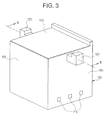
- FIG. 3 an exemplary embodiment employing outlets 120 on two opposing sides 105 proximate to the top 110 of the enclosure 100 is depicted.
- Location of the outlets 120 on two opposing sides 105 may be the result of overhead restrictions preventing the use of outlets 120 located on the top 110 as depicted in Figure 2.
- the outlets 120 may also be placed on two opposing sides 105 to allow for configuration of a flat top 110 surface, which may be used for the location of additional equipment, or for general storage.
- reference numeral 175 may represent either the equipment, or features of the equipment, such as an exhaust plenum / diffuser associated with a turbine for example. As used herein, reference numeral 175 will be used to represent the equipment located within the enclosure 100.
- an embodiment of the enclosure 100 is also configured to maintain appropriate thermal conditions, which may be necessary for proper equipment operation, or may be health-based requirements, set by the appropriate authorities.
- the enclosure 100 is used to enclose an exemplary turbine exhaust plenum / diffuser 175
- the gasses flowing through the exhaust plenum / diffuser 175 may reach temperatures of 1100 degrees Fahrenheit (593 degrees Celsius).
- proper thermal management may require a maximum internal enclosure 100 temperature of 140 degrees Fahrenheit (60 degrees Celsius).
- an exemplary exhaust plenum / diffuser may require a temperature differential less than or equal to 25 degrees Fahrenheit (14 degrees Celsius) between a top 161 center and a bottom 156 center location of the equipment 175.
- a cooling medium such as air currents depicted by wavy lines 200
- heat generated by the equipment 175 is transferred to the surrounding internal ambient air 200, causing it to expand, become less dense, and rise, until it exits via the outlets 120.
- the number and size of inlets 115 and outlets 120 will be determined by the thermal and acoustic properties of the equipment 175. Increased heat generation typically results in requiring an increase in total inlet 115 and outlet 120 area. However, if the size of inlets 115 and outlets 120 become too large, the ability of the enclosure 100 to restrict transmission of acoustic energy may be reduced.
- a ventilation area shall be defined by the size of the ventilation ports 115, 120. Accordingly, to prevent a possible flow restriction, an embodiment of the invention has a first ventilation area of the inlets 115 equal to or less than a second ventilation area of the outlets 120.
- the ratio of the second ventilation area to the first ventilation area may range from 1.1 to 1.5 depending upon the specific thermal characteristics of the embodiment. It is contemplated that a ratio of 1.1 to 1.5 will provide sufficient heat transfer while limiting the outlet opening for noise control.
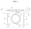
- the inlets 115 are sized and disposed so as to direct incoming air 200 to the bottom 156 center location of the equipment 175.
- the top of the opening of the inlet 115 is located lower than the bottom 156 of the equipment 175, as indicated by dimension 155.
- the actual distance represented by dimension 155 may vary depending upon such factors as inlet 115 and outlet 120 size, and enclosure 100 thermal properties, for example.
- an embodiment has the bottom of the opening of the outlets 120 located higher than the top 161 of the equipment 175, as indicated by dimension 160.
- the actual distance represented by dimension 160 may vary depending upon such factors as inlet 110 and outlet 120 size, and enclosure 100 thermal properties, for example.
- a baffle 150 may be used to direct a cooling medium such as air, maximize air stream velocity, and prevent localized areas of increased temperature.
- a cooling medium such as air
- the baffle 150 may be disposed toward the top 110 at the interior of the enclosure 100, configured to be upward sloping from a region proximate the top 161 center of the equipment 175 toward the sides 105 in which the outlets 120 are disposed.
- baffle 150 is configured and disposed so as to direct the air toward the outlets 120, creating the appropriate uniform airflow over the top 161 of the equipment 175 to prevent the formation of a localized high temperature area, thereby providing uniform equipment 175 temperature.
- FIG. 5 an exemplary embodiment employing outlets 120 on one side 105 proximate to the top 110 of the enclosure 100 is depicted.
- Location of the outlets 120 on one side 105 may be the result of overhead restrictions preventing the use of outlets 120 located on the top as depicted in Figure 2, or adjacent equipment preventing the use of outlets 120 on two sides 105 as depicted in Figure 3.
- a flat top 110 surface may allow for the location of additional equipment, or for general storage.
- FIG. 6 an embodiment of a cross sectional view of the enclosure 100 shown in Figure 5 is depicted.
- a baffle 151 with an alternate configuration is utilized.
- the baffle 151 is disposed between one side 106 and the top 110 of the enclosure 100, opposite the side 105 on which the outlets 120 are disposed.
- the baffle 150 will be upward sloping from the side 106 of the enclosure opposite the side 105 at which the outlets 120 are disposed toward the interior top 110 of the enclosure 100.
- the baffle 151 will accelerate heated air 200 towards the outlets 120 on the opposite side 105. This will increase airflow over the top 161 of the equipment 175, the equipment 175 will be uniformly cooled, and hotspots or dead/recirculation zones inside the enclosure 100 will be eliminated or substantially reduced.
- the baffle 151 is disposed such that an angle ⁇ formed between the baffle and the side 106 is about 45 degrees. As used herein, the term "about” represents deviation that may result from optimizing the particular enclosure 100 to the thermal or geometric characteristics that may be required for operation of the particular equipment 175 contained therein.
- the smallest distance (represented by reference numeral 165) from the baffle 151 to the equipment 175 will be equal to or less than the smallest distance (represented by reference numeral 170) from the equipment to the interior of the side 106.
- the location of the equipment 175 in relation to the inlets 115 and outlets 120 of an embodiment is such that the top of the opening of the inlets 115 is located lower than the bottom 156 of the equipment 175 as indicated by dimension 155.
- the configuration of inlet 115 size and location of an embodiment is such that the air currents 200 from the inlets 115 is directed toward the bottom 156 center of the equipment 175, as illustrated in Figures 4 and 6.
- an embodiment has the bottom of the opening of the outlets 120 located higher than the top 161 of the equipment 175 as indicated by dimension 160.
- some embodiments of the invention may include some of the following advantages: ability to eliminate blower use for heat removal; ability to eliminate, or at least reduce, blower noise, which can contribute to overall power plant noise levels, thereby reducing overall system noise; increased equipment uptime by eliminating blower maintenance; reduced energy consumption via elimination of blower use; and, reduction in space consumed by blower motors and fans.
Landscapes
- Engineering & Computer Science (AREA)
- Mechanical Engineering (AREA)
- General Engineering & Computer Science (AREA)
- Cooling Or The Like Of Electrical Apparatus (AREA)
Applications Claiming Priority (1)
| Application Number | Priority Date | Filing Date | Title |
|---|---|---|---|
| US11/407,624 US20070249279A1 (en) | 2006-04-20 | 2006-04-20 | System and apparatus for enclosing equipment |
Publications (1)
| Publication Number | Publication Date |
|---|---|
| EP1898070A2 true EP1898070A2 (fr) | 2008-03-12 |
Family
ID=38318663
Family Applications (1)
| Application Number | Title | Priority Date | Filing Date |
|---|---|---|---|
| EP07106553A Withdrawn EP1898070A2 (fr) | 2006-04-20 | 2007-04-20 | Système et appareil pour enfermer un équipement |
Country Status (4)
| Country | Link |
|---|---|
| US (1) | US20070249279A1 (fr) |
| EP (1) | EP1898070A2 (fr) |
| JP (1) | JP2007292072A (fr) |
| CN (1) | CN101059195A (fr) |
Cited By (1)
| Publication number | Priority date | Publication date | Assignee | Title |
|---|---|---|---|---|
| US9027351B2 (en) | 2011-06-07 | 2015-05-12 | General Electric Company | System and method for packaging and transporting a gas turbine |
Families Citing this family (7)
| Publication number | Priority date | Publication date | Assignee | Title |
|---|---|---|---|---|
| FR2934009B1 (fr) * | 2008-07-21 | 2010-09-03 | Ge Energy Products France Snc | Diffuseur d'echappement pour turbine a gaz |
| FR2955646B1 (fr) | 2010-01-26 | 2012-08-24 | Ge Energy Products France Snc | Systeme et procede de ventilation pour turbine |
| CN107370910B (zh) * | 2017-08-04 | 2019-09-24 | 西安邮电大学 | 基于最优曝光的最小包围曝光集合获取方法 |
| CN108194203A (zh) * | 2017-12-19 | 2018-06-22 | 中国船舶重工集团公司第七0三研究所 | 一种用于工业燃气轮机箱装体的分支冷却结构 |
| CN111188656B (zh) * | 2020-03-04 | 2024-06-11 | 安徽誉特双节能技术有限公司 | 一种汽轮机防护装置 |
| CN115247852B (zh) * | 2021-04-09 | 2023-09-29 | 黄荣芳 | 厂房空间散热结构 |
| CN116608566B (zh) * | 2023-05-22 | 2023-12-22 | 北京城建设计发展集团股份有限公司 | 基于建筑一体化的枢纽地下交通场站智能化被动节能系统 |
Family Cites Families (8)
| Publication number | Priority date | Publication date | Assignee | Title |
|---|---|---|---|---|
| US3817273A (en) * | 1970-05-22 | 1974-06-18 | C Erwin | Fuel system for diesel engines |
| US4122302A (en) * | 1970-10-09 | 1978-10-24 | Chester C. Pond | Two way dynamic and electrostatic speaker enclosure with side vent for greater high frequency dispersion |
| US3967545A (en) * | 1974-02-14 | 1976-07-06 | John Baker | Controlling the supply of electric current to a room |
| US5924920A (en) * | 1998-01-15 | 1999-07-20 | Flow Safe, Inc. | Fume hood having a bi-stable vortex |
| US6357221B1 (en) * | 2000-07-21 | 2002-03-19 | General Electric Company | Ventilation for an enclosure of a gas turbine and related method |
| TW511731U (en) * | 2001-01-20 | 2002-11-21 | Elanvital Corp | Pipe fan |
| US6700779B2 (en) * | 2002-07-12 | 2004-03-02 | Adc Dsl Systems, Inc. | Modular fan units |
| US6983607B2 (en) * | 2003-10-22 | 2006-01-10 | General Electric Company | Turbine compartment ventilation control system and method using variable speed fan |
-
2006
- 2006-04-20 US US11/407,624 patent/US20070249279A1/en not_active Abandoned
-
2007
- 2007-04-19 JP JP2007110012A patent/JP2007292072A/ja not_active Withdrawn
- 2007-04-20 EP EP07106553A patent/EP1898070A2/fr not_active Withdrawn
- 2007-04-20 CN CNA2007101012824A patent/CN101059195A/zh active Pending
Cited By (1)
| Publication number | Priority date | Publication date | Assignee | Title |
|---|---|---|---|---|
| US9027351B2 (en) | 2011-06-07 | 2015-05-12 | General Electric Company | System and method for packaging and transporting a gas turbine |
Also Published As
| Publication number | Publication date |
|---|---|
| CN101059195A (zh) | 2007-10-24 |
| US20070249279A1 (en) | 2007-10-25 |
| JP2007292072A (ja) | 2007-11-08 |
Similar Documents
| Publication | Publication Date | Title |
|---|---|---|
| EP1898070A2 (fr) | Système et appareil pour enfermer un équipement | |
| JP5291201B2 (ja) | 設備キャビネットの冷却空気を調整する方法およびセンサ構成 | |
| KR100917301B1 (ko) | 공조용 토출 장치 시스템, 배출열 반송 장치 시스템 및이들을 구비한 공조 시스템 | |
| CN104080314B (zh) | 冷却印刷电路板上发热元件的电子组件和方法 | |
| US6357221B1 (en) | Ventilation for an enclosure of a gas turbine and related method | |
| US7958717B2 (en) | Gas turbine power generator plant and silencer for the same | |
| KR100962400B1 (ko) | 뜨거운 공기 배출을 분리한 결합형 랙 시스템, 이를 이용한데이터 센터의 냉각 시스템 및 그 방법 | |
| US20080068791A1 (en) | Equipment and Network Cabinet | |
| CN102753901B (zh) | 用于输送空气的系统和方法 | |
| US6082094A (en) | Ventilation system for acoustic enclosures for combustion turbines and air breathing heat engines | |
| CN100584653C (zh) | 机车动态制动栅格单元的配置 | |
| US6504714B1 (en) | Multi-level thermal management system and method | |
| US8672089B2 (en) | Baffle arrangement for a genset enclosure | |
| JP6367378B2 (ja) | 逆排気プレナムモジュール | |
| US11969613B2 (en) | Explosion-proof housing | |
| CN205176998U (zh) | 一种自动售货机 | |
| KR100596307B1 (ko) | 냉동 콘테이너 선적 화물창의 통풍 덕트 시스템 | |
| CN112840292A (zh) | 用于冷却设施内的计算设备的系统和方法 | |
| JP6153772B2 (ja) | 煙突効果を利用した冷却システム及び冷却方法 | |
| JP2025502719A (ja) | 流体循環システムのための流体流れ増大装置 | |
| KR102905745B1 (ko) | 축 발전기 모터 시스템용 전기 판넬룸의 공조 시스템 및 동 시스템을 구비한 선박 | |
| KR20110087158A (ko) | 환기장치를 구비한 선박 | |
| CN115571318A (zh) | 一种机舱通风系统及船舶 | |
| CN120548578A (zh) | 气流发生器 | |
| RU2161715C2 (ru) | Устройство для охлаждения газотурбинной установки |
Legal Events
| Date | Code | Title | Description |
|---|---|---|---|
| PUAI | Public reference made under article 153(3) epc to a published international application that has entered the european phase |
Free format text: ORIGINAL CODE: 0009012 |
|
| AK | Designated contracting states |
Kind code of ref document: A2 Designated state(s): AT BE BG CH CY CZ DE DK EE ES FI FR GB GR HU IE IS IT LI LT LU LV MC MT NL PL PT RO SE SI SK TR |
|
| AX | Request for extension of the european patent |
Extension state: AL BA HR MK YU |
|
| STAA | Information on the status of an ep patent application or granted ep patent |
Free format text: STATUS: THE APPLICATION IS DEEMED TO BE WITHDRAWN |
|
| 18D | Application deemed to be withdrawn |
Effective date: 20101102 |