EP1898086B1 - Befestigungsanordnung - Google Patents
Befestigungsanordnung Download PDFInfo
- Publication number
- EP1898086B1 EP1898086B1 EP20060018803 EP06018803A EP1898086B1 EP 1898086 B1 EP1898086 B1 EP 1898086B1 EP 20060018803 EP20060018803 EP 20060018803 EP 06018803 A EP06018803 A EP 06018803A EP 1898086 B1 EP1898086 B1 EP 1898086B1
- Authority
- EP
- European Patent Office
- Prior art keywords
- tubular portion
- fixing arrangement
- snap
- cylinder head
- accordance
- Prior art date
- Legal status (The legal status is an assumption and is not a legal conclusion. Google has not performed a legal analysis and makes no representation as to the accuracy of the status listed.)
- Ceased
Links
Images

Classifications
-
- F—MECHANICAL ENGINEERING; LIGHTING; HEATING; WEAPONS; BLASTING
- F02—COMBUSTION ENGINES; HOT-GAS OR COMBUSTION-PRODUCT ENGINE PLANTS
- F02M—SUPPLYING COMBUSTION ENGINES IN GENERAL WITH COMBUSTIBLE MIXTURES OR CONSTITUENTS THEREOF
- F02M61/00—Fuel-injectors not provided for in groups F02M39/00 - F02M57/00 or F02M67/00
- F02M61/14—Arrangements of injectors with respect to engines; Mounting of injectors
Definitions
- the invention relates to a fixing arrangement for fixing a fuel injector in a cylinder head of a combustion engine and a fuel injector.
- Fuel injectors are in wide spread use, in particular for internal combustion engines where they may be arranged in order to dose fuel into an intake manifold of the internal combustion engine or directly into the combustion chamber of a cylinder of the internal combustion engine. Fuel can be supplied to the internal combustion engine by the fuel injector that comprises the fixing arrangement. The fuel injectors can be coupled to the cylinder head of the internal combustion engine in different manners.
- the coupling of the fuel injectors to the cylinder heads needs to be very precise to get a correct injection angle.
- DE 195 08 305 A1 discloses an injector nozzle holder in a cylinder head.
- the nozzle passes through a hollow screw securing it to the head or another component of the machine.
- the screw acts via an elastic component against a shoulder in the head, movement being limited by a stop.
- the elastic component can be permanently secured to a thrust ring, bearing against the nozzle shoulder, and it can consist of a sleeve-shaped compression spring, which can be integral with the ring or screw.
- the object of the invention is to create a fixing arrangement for fixing a fuel injector in a cylinder head of a combustion engine which is simply to be manufactured and which facilitates a reliable and precise coupling between the fuel injector and the cylinder head of the combustion engine.
- the invention is distinguished by a fixing arrangement for fixing a fuel injector being inserted into a cylinder head of a combustion engine in an inserting direction, wherein the fixing arrangement is formed as a snap-in arrangement.
- the fixing arrangement comprises a first tubular portion including a central longitudinal axis, comprising a snap-in recess and being designed to be rigidly coupled to the cylinder head, and a second tubular portion being designed to engage the fuel injector and to be rigidly coupled to the fuel injector.
- the second tubular portion comprises a snap-in projection extending away from the second tubular portion outwards in radial direction and is designed to be received by the snap-in recess of the first tubular portion to retain the second tubular portion in the first tubular portion in direction of the central longitudinal axis.
- the fixing arrangement has a spring element being arranged and designed to exert a force against the inserting direction of the fuel injector.
- one of the tubular portions comprises the spring element being arranged and designed to exert the axial force on the second tubular portion to fix the second tubular portion relative to the first tubular portion in axial direction.
- the spring element is arranged at an axial end of the second tubular portion, the axial end of the second tubular portion being arranged to face the cylinder head. This allows arranging and fixing the spring element between the second tubular portion and the cylinder head.
- the spring element is a leaf spring extending in axial direction. This has the advantage that the spring element can be simple realized.
- the spring element is designed to be supported on the cylinder head. This has the advantage that it is possible that only one further support for the spring element on the fixing arrangement is needed.
- the spring element is formed in one part with the second tubular portion. This has the advantage that no further elements for coupling the spring element to the second tubular portion are necessary.
- the second tubular portion has a plurality of spring elements distributed circumferentially over the second tubular portion.
- the spring elements are distributed axial symmetrically over the second tubular portion relative to the central longitudinal axis.
- the second tubular portion has a plurality of snap-in projections distributed circumferentially over the second tubular portion. This has the advantage that a homogenous distribution of the force for retaining the second tubular portion in the first tubular portion is possible.
- the snap-in projections are distributed axial symmetrically over the second tubular portion relative to the central longitudinal axis. This has the advantage that a very homogenous distribution of the force for retaining the second tubular portion in the first tubular portion is possible.
- the snap-in recess of the first tubular portion is designed as a through-hole.
- the invention is distinguished by a fuel injector comprising a fixing arrangement.
- Figure 1 shows an internal combustion engine 22, with an intake air tract 10, a motor block 12, a cylinder head 14 and an exhaust gas tract 16.
- a combustion chamber 20 is arranged in the motor block 12 .
- the cylinder head 14 comprises a fuel injector 18 and a sparking plug 19.
- a fixing arrangement 30 enables the fixing of the fuel injector 18 to the cylinder head 14 of the combustion engine 22.
- the fuel injector 18 ( figures 2 ) comprises an injector coupling portion 24 and a valve assembly 27.
- the injector coupling portion 24 is designed to be coupled to a highpressure fuel chamber of the internal combustion engine 22, the fuel is stored under high pressure, for example, under the pressure of about 200 bar in the case of a gasoline engine or of about 2,000 bar in the case of a diesel engine.
- the injector coupling portion 24 is designed to be coupled to an electrical supply to actuate a not shown actuator unit of the fuel injector 18.
- the valve assembly 27 comprises a valve body 26 with a central longitudinal axis L and a not shown cavity which is axially led through the valve body 26.
- the valve assembly 27 further comprises a not shown valve needle taken in the cavity of the valve body 26.
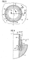
- the fixing arrangement 30 comprises a first tubular portion 32 and a second tubular portion 34 extending in the direction of the central longitudinal axis L.
- the first tubular portion 32 has a snap-in recess 50 which is carried out as a through-hole.
- a chamfer 52 is arranged at an axial end 54 of the first tubular portion 32, facing away from the cylinder head 14.
- the chamfer 52 is designed to be arranged circumferentially over the first tubular portion 32.
- the first tubular portion 32 has an outer surface 56 by which the first tubular portion 32 is coupled to the cylinder head 14.
- the cylinder head 14 has a recess 15, which engages the first tubular portion 32 partially. This enables a rigid coupling of the first tubular portion 32 to the cylinder head 14.
- the coupling between the cylinder head 14 and the first tubular portion 32 can be carried out by brazing, but it may also be done by another adequate coupling method as press-fitting or welding.
- the second tubular portion 34 of the fixing arrangement 30 has an inner surface 40 in which the fuel injector 18 with an outer surface 42 is arranged.
- the second tubular portion 34 of the fixing arrangement 30 engages the fuel injector 18 and is rigidly coupled to the fuel injector 18.
- the coupling between the fuel injector 18 and the fixing arrangement 30 is preferably carried out by welding.
- the fixing arrangement 30 further comprises snap-in projections 36 which are in one piece with the second tubular portion 34.
- the snap-in projections 36 are bent away from the second tubular portion 34 and extend outwards in radial direction from the tubular portion 32.
- the second tubular portion 34 comprises a first axial end 44 which faces away from the cylinder head 14, and a second axial end 46, which is facing the cylinder head 14.
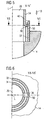
- a spring element 38 is arranged at the second axial end 46 of the second tubular portion 44.
- the spring element 38 is designed as a leaf spring which extends in axial direction.
- the spring element 38 is supported on the cylinder head 14 and is designed to exert an axial force F on the second tubular portion 34 to fix the second tubular portion 34 relative to the first tubular portion 32 in axial direction.
- the spring element 38 is formed in one part with the second tubular portion 34.
- the second tubular portion 34 of the shown embodiment of the fixing arrangement 30 has three snap-in projections 36 and two spring elements 38.
- the three snap-in projections 36 are arranged in an angular distance of 120° to each other, thereby being distributed axial-symmetrically over the second tubular portion 34 relative to the central longitudinal axis L.
- the number of the snap-in projections 36 may vary but it is preferred that the snap-in projections 36 are distributed axial-symmetrically over the circumference of the second tubular portion 34 to get a very homogenous distribution of the retaining force between the first tubular portion 32 and the second tubular portion 34.
- the two spring elements 38 of the second tubular portion 34 are opposing each other relative to the central longitudinal axis L.
- the number of spring elements 38 may differ from three but it is preferred that the spring elements 38 are distributed axial-symmetrically over the circumference of the second tubular portion 34 relative to the central longitudinal axis L as to obtain a very homogenous distribution of the axial forces F on the second tubular portion 34 to fix the second tubular portion 34 relative to the first tubular portion 32 in axial direction.
- the first tubular portion 32 is inserted into the recess 15 of the cylinder head 14. As the outer surface 56 of the first tubular portion 32 is in contact with the cylinder head 14, a fixed coupling of the cylinder head 14 to the first tubular portion 32 is enabled, preferably by brazing, press-fitting or welding.
- the fuel injector is inserted into the second tubular portion 34.
- the outer surface 42 of the fuel injector 18 is in contact with the inner surface 40 of the second tubular portion 34, thereby enabling a fixed coupling of the second tubular portion 34 to the fuel injector 18, preferably by welding.
- the fuel injector 18 with the second tubular portion 34 is inserted in an inserting direction D into the first tubular portion 32 with the assistance of the chamfer 52, which engages the snap-in projections 36 of the second tubular portion 34.
- the snap-in projections 36 are moving in direction of the inserting direction D until the snap-in projections 36 come into engagement with the snap-in recesses 50 of the first tubular portion 32.
- the spring element 38 is compressed as it is in contact with the cylinder head 14.
- the spring elements 38 are compressed and exert the axial force F on the second tubular portion 34.
- the second tubular portion 34 is fixed relative to the first tubular portion 32 in axial direction.
- a tool can be inserted into the snap-in recesses 50 which are formed as through-holes and the snap-in projections 36 can be moved into radial direction towards the central longitudinal axis L until the snap-in projections 36 disengage with the snap-in recesses 50 in the first tubular portion 32. Subsequently, the second tubular portion 34 with the injector 18 can be pulled out from the first tubular portion 32 in the cylinder head 14.
- the construction of the fixing arrangement 30 as a snap-in arrangement allows a fast and simple assembly and disassembly of the fuel injector 18 and the cylinder head 14.
Landscapes
- Engineering & Computer Science (AREA)
- Chemical & Material Sciences (AREA)
- Combustion & Propulsion (AREA)
- Mechanical Engineering (AREA)
- General Engineering & Computer Science (AREA)
- Fuel-Injection Apparatus (AREA)
- Cylinder Crankcases Of Internal Combustion Engines (AREA)
Claims (13)
- Befestigungsanordnung (30) zum Befestigen eines Kraftstoffinjektors (18), der in einen Zylinderkopf (14) einer Brennkraftmaschine (22) in einer Einsetzrichtung (D) eingesetzt wird, während die Befestigungsanordnung (30) ausgebildet ist als eine Einschnappanordnung und umfasst:einen ersten rohrförmigen Bereich (32), der eine zentrale Längsachse (L) aufweist, eine Einschnappaussparung (50) umfasst und gestaltet ist, um starr an den Zylinderkopf (14) gekoppelt zu werden, undeinen zweiten rohrförmigen Bereich (34), der gestaltet ist, um mit dem Kraftstoffinjektor (18) in Eingriff zu stehen,dadurch gekennzeichnet, dass
der zweite rohrförmige Bereich (34) starr an den Kraftstoffinjektor (18) gekoppelt ist und einen Einschnappvorsprung (36) aufweist, der sich von dem zweiten rohrförmigen Bereich (34) auswärts in radialer Richtung weg erstreckt und der gestaltet ist, um in der Einschnappaussparung (50) des ersten rohrförmigen Bereichs (32) aufgenommen zu werden, um den zweiten rohrförmigen Bereich (34) in dem ersten rohrförmigen Bereich (32) in Richtung der zentralen Längsachse (L) zu halten. - Befestigungsanordnung (30) gemäß Anspruch 1, mit einem Federelement (38), das angeordnet und gestaltet ist, um eine Kraft (F) entgegen der Einsetzrichtung (D) des Kraftstoffinjektors (18) auszuüben.
- Befestigungsanordnung (30) gemäß Anspruch 1 oder 2, während einer der rohrförmigen Bereiche (32, 34) das Federelement (38) umfasst, das angeordnet und gestaltet ist, um die axiale Kraft (F) auf den zweiten rohrförmigen Bereich (34) auszuüben, um den zweiten rohrförmigen Bereich (34) im Bezug auf den ersten rohrförmigen Bereich (32) in axialer Richtung zu befestigen.
- Befestigungsanordnung (30) gemäß einem der vorhergehenden Ansprüche, während das Federelement (38) an einem axialen Ende (46) des zweiten rohrförmigen Bereichs (34) angeordnet ist, wobei das axiale Ende (46) des zweiten rohrförmigen Bereichs angeordnet ist, um dem Zylinderkopf (14) gegenüberzustehen.
- Befestigungsanordnung (30) gemäß einem der vorhergehenden Ansprüche, während das Federelement (38) eine Blattfeder ist, die sich in axialer Richtung erstreckt.
- Befestigungsanordnung (30) gemäß einem der vorhergehenden Ansprüche, während das Federelement (38) gestaltet ist, um auf dem Zylinderkopf (14) unterstützt zu werden.
- Befestigungsanordnung (30) gemäß einem der vorhergehenden Ansprüche, während das Federelement (38) einteilig mit dem zweiten rohrförmigen Bereich (34) ausgebildet ist.
- Befestigungsanordnung (30) gemäß einem der vorhergehenden Ansprüche, während der zweiten rohrförmige Bereich (34) eine Mehrzahl an Federelementen (38) aufweist, die umfänglich über den zweiten rohrförmigen Bereich (34) verteilt sind.
- Befestigungsanordnung (30) gemäß Anspruch 8, während die Federelemente (38) axial symmetrisch über den zweiten rohrförmigen Bereich (34) relativ zu der zentralen Längsachse (L) verteilt sind.
- Befestigungsanordnung (30) gemäß einem der vorhergehenden Ansprüche, während der zweite rohrförmige Bereich (34) eine Mehrzahl an Einschnappvorsprüngen (36) aufweist, die umfänglich über den zweiten rohrförmigen Bereich (34) verteilt sind.
- Befestigungsanordnung (30) gemäß Anspruch 10, während die Einschnappvorsprünge (36) axial symmetrisch über den zweiten rohrförmigen Bereich (34) relativ zu der zentralen Längsachse (L) verteilt sind.
- Befestigungsanordnung (30) gemäß einem der vorhergehenden Ansprüche, während die Einschnappaussparung (50) des ersten rohrförmigen Bereichs (32) als eine Durchgangsbohrung gestaltet ist.
- Kraftstoffinjektor (18) umfassend eine Befestigungsanordnung (30) gemäß einem der vorhergehenden Ansprüche.
Priority Applications (2)
| Application Number | Priority Date | Filing Date | Title |
|---|---|---|---|
| EP20060018803 EP1898086B1 (de) | 2006-09-07 | 2006-09-07 | Befestigungsanordnung |
| DE200660012976 DE602006012976D1 (de) | 2006-09-07 | 2006-09-07 | Befestigungsanordnung |
Applications Claiming Priority (1)
| Application Number | Priority Date | Filing Date | Title |
|---|---|---|---|
| EP20060018803 EP1898086B1 (de) | 2006-09-07 | 2006-09-07 | Befestigungsanordnung |
Publications (2)
| Publication Number | Publication Date |
|---|---|
| EP1898086A1 EP1898086A1 (de) | 2008-03-12 |
| EP1898086B1 true EP1898086B1 (de) | 2010-03-17 |
Family
ID=37772840
Family Applications (1)
| Application Number | Title | Priority Date | Filing Date |
|---|---|---|---|
| EP20060018803 Ceased EP1898086B1 (de) | 2006-09-07 | 2006-09-07 | Befestigungsanordnung |
Country Status (2)
| Country | Link |
|---|---|
| EP (1) | EP1898086B1 (de) |
| DE (1) | DE602006012976D1 (de) |
Family Cites Families (4)
| Publication number | Priority date | Publication date | Assignee | Title |
|---|---|---|---|---|
| DE19508305A1 (de) | 1995-03-09 | 1996-09-12 | Bayerische Motoren Werke Ag | Vorrichtung zur Halterung einer Einspritzdüse an einem Maschinenteil, insbesondere im/am Zylinderkopf einer Brennkraftmaschine |
| DE19508304A1 (de) * | 1995-03-09 | 1996-09-12 | Bayerische Motoren Werke Ag | Vorrichtung zur Halterung einer Einspritzdüse in einem Leichtmetall-Zylinderkopf einer Brennkraftmaschine |
| DE10027669A1 (de) * | 2000-06-03 | 2001-12-06 | Bosch Gmbh Robert | Befestigungsmittel für ein Brennstoffeinspritzventil |
| DE10133264A1 (de) * | 2001-07-09 | 2003-02-06 | Bosch Gmbh Robert | Befestigungsvorrichtung |
-
2006
- 2006-09-07 EP EP20060018803 patent/EP1898086B1/de not_active Ceased
- 2006-09-07 DE DE200660012976 patent/DE602006012976D1/de active Active
Also Published As
| Publication number | Publication date |
|---|---|
| DE602006012976D1 (de) | 2010-04-29 |
| EP1898086A1 (de) | 2008-03-12 |
Similar Documents
| Publication | Publication Date | Title |
|---|---|---|
| EP2103804B1 (de) | Kupplungsanordnung | |
| JP5810726B2 (ja) | 直噴式エンジン用フューエルレールアッシーの組付方法 | |
| EP2093414B1 (de) | Kupplungsvorrichtung | |
| US7942453B2 (en) | Coupling device | |
| EP2208883B1 (de) | Kupplungsvorrichtung | |
| EP2375052A1 (de) | Kraftstoffeinspritzanordnung | |
| EP2080893B1 (de) | Ventilanordnung für ein Einspritzventil und Einspritzventil | |
| US11035333B1 (en) | Duct assembly for fuel injection systems in engines | |
| EP1898086B1 (de) | Befestigungsanordnung | |
| EP1998038B1 (de) | Befestigungsvorrichtung zum Befestigen einer Kraftstoffeinspritzdüse in einem Zylinderkopf eines Verbrennungsmotors | |
| EP2251541B1 (de) | Kraftstoffeinspritzdüse und Kraftstoffeinspritzsystem | |
| EP1884657B1 (de) | Befestigungsvorrichtung zur Befestigung eines Brennstoffeinspritzventils an einem Zylinderkopf einer Brennkraftmaschine | |
| US6328230B1 (en) | Fuel injector for an internal combustion engine | |
| EP2292920B1 (de) | Kupplungsvorrichtung | |
| EP2090773B1 (de) | Kraftstoffeinspritzdüse | |
| KR101767353B1 (ko) | 연료 분사기 및 연료 분사 시스템 | |
| JP2002532654A (ja) | 燃料噴射弁の組立及び分解のための組立装置 | |
| EP2090772B1 (de) | Verbindungsanordnung | |
| EP2518304B1 (de) | Kraftstoffeinspritzdüse und Kraftstoffeinspritzsystem | |
| EP1803929B1 (de) | Einpritzventil und Herstellungsverfahren eines solchen Einspritzventils | |
| US6863054B2 (en) | Fuel injection system | |
| EP1559907B2 (de) | Einspritzventil mit Mittel, um Ventilnadelrotation zu verhindern | |
| EP2003329B1 (de) | Elektrischer Verbinder für einen Injektor, Aktuatoreinheit für einen Injektor, Injektor und Verfahren zur Kopplung eines ersten Verbinderelements mit einem zweiten Verbinderelement eines elektrischen Verbinders für einen Injektor | |
| EP1795741B1 (de) | Nadelvorrichtung | |
| EP1816344A1 (de) | Düsenanordnung für eine Einspritzdüse und Einspritzdüse |
Legal Events
| Date | Code | Title | Description |
|---|---|---|---|
| PUAI | Public reference made under article 153(3) epc to a published international application that has entered the european phase |
Free format text: ORIGINAL CODE: 0009012 |
|
| AK | Designated contracting states |
Kind code of ref document: A1 Designated state(s): AT BE BG CH CY CZ DE DK EE ES FI FR GB GR HU IE IS IT LI LT LU LV MC NL PL PT RO SE SI SK TR |
|
| AX | Request for extension of the european patent |
Extension state: AL BA HR MK YU |
|
| RAP1 | Party data changed (applicant data changed or rights of an application transferred) |
Owner name: CONTINENTAL AUTOMOTIVE GMBH |
|
| 17P | Request for examination filed |
Effective date: 20080912 |
|
| AKX | Designation fees paid |
Designated state(s): DE FR IT |
|
| GRAP | Despatch of communication of intention to grant a patent |
Free format text: ORIGINAL CODE: EPIDOSNIGR1 |
|
| GRAS | Grant fee paid |
Free format text: ORIGINAL CODE: EPIDOSNIGR3 |
|
| GRAA | (expected) grant |
Free format text: ORIGINAL CODE: 0009210 |
|
| AK | Designated contracting states |
Kind code of ref document: B1 Designated state(s): DE FR IT |
|
| REF | Corresponds to: |
Ref document number: 602006012976 Country of ref document: DE Date of ref document: 20100429 Kind code of ref document: P |
|
| PLBE | No opposition filed within time limit |
Free format text: ORIGINAL CODE: 0009261 |
|
| STAA | Information on the status of an ep patent application or granted ep patent |
Free format text: STATUS: NO OPPOSITION FILED WITHIN TIME LIMIT |
|
| 26N | No opposition filed |
Effective date: 20101220 |
|
| REG | Reference to a national code |
Ref country code: FR Ref legal event code: PLFP Year of fee payment: 11 |
|
| REG | Reference to a national code |
Ref country code: FR Ref legal event code: PLFP Year of fee payment: 12 |
|
| REG | Reference to a national code |
Ref country code: FR Ref legal event code: PLFP Year of fee payment: 13 |
|
| PGFP | Annual fee paid to national office [announced via postgrant information from national office to epo] |
Ref country code: FR Payment date: 20180925 Year of fee payment: 13 Ref country code: IT Payment date: 20180925 Year of fee payment: 13 |
|
| PGFP | Annual fee paid to national office [announced via postgrant information from national office to epo] |
Ref country code: DE Payment date: 20180930 Year of fee payment: 13 |
|
| REG | Reference to a national code |
Ref country code: DE Ref legal event code: R119 Ref document number: 602006012976 Country of ref document: DE |
|
| PG25 | Lapsed in a contracting state [announced via postgrant information from national office to epo] |
Ref country code: DE Free format text: LAPSE BECAUSE OF NON-PAYMENT OF DUE FEES Effective date: 20200401 |
|
| PG25 | Lapsed in a contracting state [announced via postgrant information from national office to epo] |
Ref country code: IT Free format text: LAPSE BECAUSE OF NON-PAYMENT OF DUE FEES Effective date: 20190907 |
|
| PG25 | Lapsed in a contracting state [announced via postgrant information from national office to epo] |
Ref country code: FR Free format text: LAPSE BECAUSE OF NON-PAYMENT OF DUE FEES Effective date: 20190930 |