EP1898097B1 - Wasserpumpe sowie Wasserspielanlage mit Pumpe - Google Patents
Wasserpumpe sowie Wasserspielanlage mit Pumpe Download PDFInfo
- Publication number
- EP1898097B1 EP1898097B1 EP07016603A EP07016603A EP1898097B1 EP 1898097 B1 EP1898097 B1 EP 1898097B1 EP 07016603 A EP07016603 A EP 07016603A EP 07016603 A EP07016603 A EP 07016603A EP 1898097 B1 EP1898097 B1 EP 1898097B1
- Authority
- EP
- European Patent Office
- Prior art keywords
- water
- pump
- motor
- control
- housing part
- Prior art date
- Legal status (The legal status is an assumption and is not a legal conclusion. Google has not performed a legal analysis and makes no representation as to the accuracy of the status listed.)
- Active
Links
Images

Classifications
-
- F—MECHANICAL ENGINEERING; LIGHTING; HEATING; WEAPONS; BLASTING
- F04—POSITIVE - DISPLACEMENT MACHINES FOR LIQUIDS; PUMPS FOR LIQUIDS OR ELASTIC FLUIDS
- F04D—NON-POSITIVE-DISPLACEMENT PUMPS
- F04D13/00—Pumping installations or systems
- F04D13/02—Units comprising pumps and their driving means
- F04D13/06—Units comprising pumps and their driving means the pump being electrically driven
-
- F—MECHANICAL ENGINEERING; LIGHTING; HEATING; WEAPONS; BLASTING
- F04—POSITIVE - DISPLACEMENT MACHINES FOR LIQUIDS; PUMPS FOR LIQUIDS OR ELASTIC FLUIDS
- F04D—NON-POSITIVE-DISPLACEMENT PUMPS
- F04D15/00—Control, e.g. regulation, of pumps, pumping installations or systems
- F04D15/0066—Control, e.g. regulation, of pumps, pumping installations or systems by changing the speed, e.g. of the driving engine
-
- F—MECHANICAL ENGINEERING; LIGHTING; HEATING; WEAPONS; BLASTING
- F04—POSITIVE - DISPLACEMENT MACHINES FOR LIQUIDS; PUMPS FOR LIQUIDS OR ELASTIC FLUIDS
- F04D—NON-POSITIVE-DISPLACEMENT PUMPS
- F04D15/00—Control, e.g. regulation, of pumps, pumping installations or systems
- F04D15/0088—Testing machines
-
- H—ELECTRICITY
- H02—GENERATION; CONVERSION OR DISTRIBUTION OF ELECTRIC POWER
- H02K—DYNAMO-ELECTRIC MACHINES
- H02K11/00—Structural association of dynamo-electric machines with electric components or with devices for shielding, monitoring or protection
- H02K11/30—Structural association with control circuits or drive circuits
- H02K11/33—Drive circuits, e.g. power electronics
-
- H—ELECTRICITY
- H02—GENERATION; CONVERSION OR DISTRIBUTION OF ELECTRIC POWER
- H02K—DYNAMO-ELECTRIC MACHINES
- H02K11/00—Structural association of dynamo-electric machines with electric components or with devices for shielding, monitoring or protection
- H02K11/30—Structural association with control circuits or drive circuits
- H02K11/35—Devices for recording or transmitting machine parameters, e.g. memory chips or radio transmitters for diagnosis
Definitions
- the invention relates to a water pump, in particular for fountains or water features and garden ponds, with the features of claim 1 and a water play system with pump having the features of claim 7.
- Controllable water pumps are known as part of a heating system of buildings ( WO 99/01665 as the closest prior art), are used as a cooling water pump in internal combustion engines ( EP 0 778 649 A1 ) or have electrically commutatable motors as wet rotor ( EP 1 391 984 A2 ).
- EP 0 481 423 A1 is proposed in a metal housing gear pump proposed without adverse shaft bearing on the engine.
- the invention is therefore concerned with the problem of creating a suitable for fountains and water features water pump, which can be used with reduced costs and allows for simple control variable water effects.
- the solution of the problem lies in the water pump according to the invention with the features of claim 1 and a plurality of these pumps having water play system with the features of claim 7.
- the pump By combining the use of an electronically commutated motor (EC motor), a control electronics and control electronics with speed detection, processor, data storage and BUS control module, the pump is designed as an autonomous unit, by means of watertight encapsulated in the motor housing electronics to the conditions in Area of fountains, garden ponds o. The like. Adapted installations. The complete intelligence required for precise control is contained within the pump itself. The processor and software assisted control allows a desired pump speed to be actually achieved and maintained to provide a closed loop control where speed is continuously determined. adjusted and possibly adjusted.
- EC motor electronically commutated motor
- speed detection processor
- processor data storage and BUS control module
- the rotational speed detection device may have a rotational speed sensor which is designed to detect the rotor position and the rotational frequency. This may be, for example, a Hall sensor. However, it is also possible and realizable by the inherent intelligence of the pump without additional cost of materials to form the speed detection device sensorless. In this case, the current flow inducted back by the magnet rotor is measured at each instant at the coil or coils which are not currently receiving current and which are not switched at the moment, and the rotor position is determined therefrom. The speed at which the coils which re-induce a current flow change changes the rotational frequency. Both information is evaluated by the processor and used for speed control.
- the data memory of the pump according to the invention may preferably contain a plurality of invocable programs for different types of pump operation, which can be optionally activated without opening the pump from the outside.
- a Use of the pump in garden ponds can thus be retrieved via an external control unit for user-prepared programs, such as summer or winter programs, programs for much or little fish stock, time-adapted time profiles or the like.
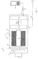
- water pump has a housing 1, which is divided into a pump housing part 2 and a motor housing part 3.
- the pump housing part 2 has a suction opening 4, which forms the water inlet, and an outlet opening 5, which serves the water outlet.
- an impeller 8 is arranged on a rotatable shaft 9.
- the shaft 9 extends out of the pump housing part 2 in the motor housing part 3 and in this in an EC motor.
- the EC motor has a rotatably connected to the shaft 9 rotor 14 and a surrounding stator 12.
- the rotor 14 is bipolar and the stator 12 six poles (or two-pole at safety extra-low voltage) is formed. This supports in an optimal cost-benefit ratio the special control and regulating dynamics of the pump described below.
- the shaft 9 is in one Bearing shield 10 mounted, which shields the motor mechanically from the pump housing part 2 and the impeller 8.
- control and regulation electronics which is preferably also arranged in the motor housing 3 and thus spaced from the water-carrying parts.
- the control electronics and the control electronics can be cast watertight for safety reasons. This also applies to the stator 12 of the motor. If stator 12 and rotor 14 are so far separated from each other by a so-called canned, preferably the entire free motor housing part may be sealed waterproof.
- the entire power electronics 16 which also includes the pure control electronics of the pump, arranged on a first board close to the motor board.
- a bus control module that receives from outside the pump sent to the pump data bus signals and converts into an activity of the pump. Between the two boards 16 and 17 takes place within the pump, a mutual exchange of information.
- the pump has an electrical power input 26 and an independent control line input 27 through which the control information is fed. From the electrical power input 26 from a power cord 36 leaves the pump housing 1, while with the control line input 27, a control data cable 37 is connected to a control panel 47.
- the two cables 36, 37 extend in a common sheath, but they are preferably also optically recognizable separated, whereby misconnections are avoided.
- Fig. 2 is shown in the upper left area a fountain or fountain system conventional type.
- a plurality of nozzles 50 are each controlled via their own proportional valve 51 and their own electrical leads 55.
- the electric cables 55 are connected to an external controller 57.
- a central pump 53 is connected, which always leads via pipelines 54 under full load continuously to the proportional valves 51.
- the proportional valves 51 then enable or interrupt the flow of water to the nozzles 50, switched by the controller 57.
- a novel water feature or fountain system which has a plurality of pumps 33 according to the invention. These are connected to a common control device in the form of the control panel 47.
- the system has the same number of nozzles 50 as the conventional system. In contrast to the upper system, however, each nozzle 50 has its own pump 33 associated with the system according to the invention.
- the pumps are connected via control cable 37 to the control panel 47. Even if other control systems are possible, a standardized BUS system with digital signal transmission is particularly preferred for this purpose.
- the pumps 33 may be connected to the control panel 47 via an electrical or electronic series connection.
- the pumps 33 according to the invention have an excellent control and regulating dynamics, which allows a precise control of the pump 33 and thus allows unexpected effects.
- the control behavior in the lower range is exactly the same as in the upper range. This control behavior can not be achieved with conventional technology.
Landscapes
- Engineering & Computer Science (AREA)
- Mechanical Engineering (AREA)
- General Engineering & Computer Science (AREA)
- Power Engineering (AREA)
- Microelectronics & Electronic Packaging (AREA)
- Control Of Positive-Displacement Pumps (AREA)
- Control Of Non-Positive-Displacement Pumps (AREA)
- Structures Of Non-Positive Displacement Pumps (AREA)
- Special Spraying Apparatus (AREA)
- Aeration Devices For Treatment Of Activated Polluted Sludge (AREA)
Description
- Die Erfindung betrifft eine Wasserpumpe, insbesondere für Springbrunnen bzw. Wasserspielanlagen sowie Gartenteiche, mit den Merkmalen des Anspruchs 1 sowie eine Wasserspielanlage mit Pumpe mit den Merkmalen des Anspruchs 7.
- Herkömmliche Wasserpumpen für Gartenteiche und Springbrunnen werden in der Praxis extern gesteuert, wenn die Art und Höhe des Wasserstrahls oder ganz generell Start und Stop der Pumpe beeinflußt werden soll. Um in Springbrunnenanlagen, vorwiegend bei mehrstrahligen Wasserspielanlagen, spezielle Wassereffekte zu erzielen, erfolgt bei herkömmlichen Pumpen die Regelung der Wassermenge pro Wasseraustritt über elektrische, magnetische oder pneumatische Stellventile (
US 4,948,046 ;DE 1 177 564 ). Dabei speist eine einzelne, große Pumpe das Wasser in ein Verteilungssystem ein, in dem einzelne, den nachfolgenden Wasserdüsen zugeordnete Stellventile über eine externe Steuerung aktiviert werden. Diese Systeme reagieren sehr träge und sind nur ungenau zu steuern. Außerdem stellen die elektrischen Stellventile einen hohen Kostenfaktor dar. Auch die aufwendige Verkabelung, die Verrohrung und die Steuerung erzeugen hohe Systemkosten. Darüber hinaus sind die laufenden Betriebskosten hoch, da die Pumpe stets unter voller Last läuft. Alternativ kommen Asynchronpumpen in Betracht, die über eine Phasenanschnittsteuerung gesteuert werden. Auch diese Steuerungen sind jedoch teuer, träge in der Reaktion und schwer zu kontrollieren. Regelbare Wasserpumpen sind als Teil einer Heizungsanlage von Gebäuden bekannt (WO 99/01665 EP 0 778 649 A1 ) eingesetzt oder weisen elektrisch kommutierbare Motoren als Naßläufer auf (EP 1 391 984 A2 ). InEP 0 481 423 A1 ist eine in einem Metallgehäuse vorgesehene Zahnradpumpe ohne nachteilige Wellenlager am Motor vorgeschlagen. - Die Erfindung befaßt sich daher mit dem Problem, eine für Springbrunnen und Wasserspiele geeignete Wasserpumpe zu schaffen, die mit verringerten Kosten einsetzbar ist und bei einfacher Steuerung variable Wasser-Effekte ermöglicht. Die Lösung der Aufgabe liegt in der erfindungsgemäßen Wasserpumpe mit den Merkmalen des Anspruchs 1 und einer eine Mehrzahl dieser Pumpen aufweisenden Wasserspielanlage mit den Merkmalen des Anspruchs 7.
- Durch die Kombination der Verwendung eines elektronisch kommutierten Motors (EC-Motor), einer Steuerelektronik und einer Regelungselektronik mit Drehzahlerkennung, Prozessor, Datenspeicher sowie BUS-Steuermodul wird die Pumpe als autonome Einheit ausgebildet, die mittels der im Motorgehäuse wasserdicht vergossenen Elektronik an die Bedingungen im Bereich von Springbrunnen, Gartenteichen o. dgl. Anlagen angepaßt ist. Die komplette für eine präzise Regelung notwendige Intelligenz sitzt dabei in der Pumpe selbst. Die prozessor- und softwareunterstützte Regelung ermöglicht es, daß eine gewünschte Drehzahl der Pumpe tatsächlich erreicht und gehalten wird, so daß ein geschlossener Regelkreis vorliegt, bei der die Drehzahl kontinuierlich ermittelt, abgeglichen und eventuell angepaßt wird.
- Die Drehzahlerkennungseinrichtung kann einen Drehzahlsensor aufweisen, der zur Erkennung der Rotorlage und der Drehfrequenz ausgelegt ist. Hierbei kann es sich beispielsweise um einen Hall-Sensor handeln. Es ist jedoch auch möglich und durch die der Pumpe innewohnende Intelligenz ohne zusätzlichen Materialaufwand realisierbar, die Drehzahlerkennungseinrichtung sensorlos auszubilden. Dabei wird zu jedem Zeitpunkt an der bzw. den gerade nicht Strom aufnehmenden Spulen, die in dem Moment nicht geschaltet sind, der durch den Magnetrotor rückinduzierte Stromfluß gemessen und aus diesem die Rotorlage ermittelt. Die Geschwindigkeit, mit der sich die einen rückinduzierten Stromfluß abgebenden Spulen ändern, gibt dabei die Drehfrequenz an. Beide Informationen werden über den Prozessor ausgewertet und zur Drehzahlregelung herangezogen.
- Der Datenspeicher der erfindungsgemäßen Pumpe kann bevorzugt mehrere aufrufbare Programme für unterschiedliche Arten des Pumpenbetriebs enthalten, die ohne Öffnung der Pumpe von außen wahlweise aktivierbar sind. Beispielsweise bei einer Verwendung der Pumpe in Gartenteichen können so über eine externe Bedieneinheit für vom Benutzer vorgefertigte Programme, beispielsweise Sommer- oder Winterprogramme, Programme für viel oder wenig Fischbesatz, tageszeitangepaßte Zeitprofile oder dergleichen abgerufen werden.
- Weitere Vorteile und Einzelheiten ergeben sich aus den Unteransprüchen und in den Zeichnungen dargestellten Ausführungsbeispielen der Erfindung, die im folgenden beschrieben werden; es zeigen:
- Fig. 1
- schematisch eine erfindungsgemäße Pumpe und
- Fig. 2
- schematisch den Aufbau einer Wasserspielanlage auf konventionelle Art und im Gegensatz dazu unter Verwendung der erfindungsgemäßen Pumpen.
- Die in
Fig. 1 dargestellte Wasserpumpe besitzt ein Gehäuse 1, das sich in einen Pumpengehäuseteil 2 und einen Motorgehäuseteil 3 untergliedert. Der Pumpengehäuseteil 2 besitzt eine Ansaugöffnung 4, die den Wassereinlaß bildet, und eine Austrittsöffnung 5, die dem Wasserauslaß dient. Im Pumpengehäuseteil 2 ist ein Laufrad 8 auf einer rotierbaren Welle 9 angeordnet. Die Welle 9 erstreckt sich aus dem Pumpengehäuseteil 2 heraus in den Motorgehäuseteil 3 und in diesem in einen EC-Motor. Der EC-Motor besitzt einen mit der Welle 9 drehfest verbundenen Rotor 14 und einen diesen umgebenden Stator 12. Bevorzugt ist der Rotor 14 zweipolig und der Stator 12 sechspolig (oder zweipolig bei Schutzkleinspannung) ausgebildet. Dies unterstützt in optimalem Kosten-Nutzenverhältnis die nachfolgend noch beschriebene besondere Steuer- und Regeldynamik der Pumpe. Die Welle 9 ist in einem Lagerschild 10 gelagert, das den Motor mechanisch vom Pumpengehäuseteil 2 und dem Laufrad 8 abschirmt. - Im Gehäuse 1 befindet sich weiterhin eine Steuer- und Regelungselektronik, die bevorzugt ebenfalls im Motorgehäuse 3 und damit beabstandet von den wasserführenden Teilen angeordnet ist. Die Steuerelektronik und die Regelungselektronik kann aus Sicherheitsgründen wasserdicht vergossen sein. Dies trifft ebenfalls auf den Stator 12 des Motors zu. Sofern Stator 12 und Rotor 14 insoweit durch ein sogenanntes Spaltrohr voneinander getrennt sind, kann bevorzugt der gesamte freie Motorgehäuseteil wasserdicht vergossen sein.
- Bei der
Fig. 1 dargestellten Ausführungsform ist auf einer ersten motornahen Platine die gesamte Leistungselektronik 16, die ebenfalls die reine Steuerungselektronik der Pumpe beinhaltet, angeordnet. Auf einer dahintersitzenden Platine 17 befindet sich die Regelungselektronik mit Mikroprozessor und Datenspeicher sowie im Beispielsfall einem BUS-Steuerungsmodul, daß von außerhalb der Pumpe in die Pumpe gesandte Daten-BUS-Signale aufnimmt und in eine Aktivität der Pumpe umsetzt. Zwischen den beiden Platinen 16 und 17 findet innerhalb der Pumpe ein gegenseitiger Informationsaustausch statt. Die Pumpe verfügt über einen elektrischen Leistungseingang 26 und einen davon unabhängigen Steuerleitungseingang 27 durch den die Steuerinformationen eingespeist werden. Vom elektrischen Leistungseingang 26 aus verläßt ein Netzkabel 36 das Pumpengehäuse 1, während mit dem Steuerleitungseingang 27 ein Steuerdatenkabel 37 mit einem Kontrollpaneel 47 verbunden ist. Selbstverständlich können die beiden Kabel 36, 37 in einer gemeinsamen Ummantelung verlaufen, bevorzugt sind sie jedoch auch optisch erkennbar getrennt, wodurch Fehlanschlüsse vermieden werden. - In
Fig. 2 ist im oberen linken Bereich eine Wasserspiel- bzw. Springbrunnenanlage konventioneller Art dargestellt. Dabei werden mehrere Düsen 50 jeweils über ein eigenes Proportionalventil 51 und jeweils eigene Elektroleitungen 55 gesteuert. Dazu sind die Elektroleitungen 55 mit einer externen Steuerung 57 verbunden. An die externe Steuerung 57 ist auch eine zentrale Pumpe 53 angeschlossen, die über Rohrleitungen 54 stets unter Volllast laufend zu den Proportionalventilen 51 führt. Die Proportionalventile 51 geben dann von der Steuerung 57 geschaltet den Wasserfluß zu den Düsen 50 frei oder unterbrechen diesen. - Darunter ist eine neuartige Wasserspielanlage bzw. Springbrunnenanlage dargestellt, die mehrere der erfindungsgemäßen Pumpen 33 aufweist. Diese sind mit einer gemeinsamen Kontrolleinrichtung in Form des Kontrollpaneels 47 verbunden. Die Anlage weist dieselbe Anzahl von Düsen 50 wie die herkömmliche Anlage auf. Im Gegensatz zu der oberen Anlage ist jedoch bei der erfindungsgemäßen Anlage jeder Düse 50 eine eigene Pumpe 33 zugeordnet. Die Pumpen sind über Steuerkabel 37 mit dem Kontrollpaneel 47 verbunden. Auch wenn andere Steuerungssysteme möglich sind, ist hierzu insbesondere ein standardisiertes BUS-System mit digitaler Signalübermittlung bevorzugt. Die Pumpen 33 können wie dargestellt mit dem Kontrollpaneel 47 über eine elektrische bzw. elektronische Reihenschaltung verbunden werden.
- Während bei dem herkömmlichen System eine komplexe Steuerung 57 von außen notwendig ist, sitzt bei dem neuen System die komplette Intelligenz in den jeweiligen Pumpen 33. Der Verdrahtungsaufwand wird auf ein Minimum reduziert, und eine aufwendige Verrohrung entfällt gänzlich. Zudem sind Pumpen mit EC-Motoren preiswert herzustellen und haben einen hohen Wirkungsgrad, der die laufenden Betriebskosten vermindert. Der Energieverbrauch bei der neuartigen Anlage verläuft etwa proportional zur abverlangten Drehzahl, entsprechend dem Wasserdurchfluß. So würde die oben dargestellte konventionelle Anlage eine bis zu dreifache Leistungsaufnahme haben als eine vergleichbare neuartige Anlage.
- Die erfindungsgemäßen Pumpen 33 besitzen eine hervorragende Steuer- und Regeldynamik, die eine präzise Regelung der Pumpe 33 ermöglicht und somit ungeahnte Effekte erlaubt. Das Regelverhalten im unteren Bereich ist genauso exakt wie im oberen Bereich. Dieses Regelverhalten läßt sich mit konventioneller Technik nicht erreichen.
Claims (9)
- Wasserpumpe für Springbrunnen, Gartenteiche, Wasserspiele o. dgl. Anlagen, mit einem Gehäuse (1), das einen eine Ansaugöffnung (4) und eine Austrittsöffnung (5) aufweisenden Pumpengehäuseteil (2), in dem ein Laufrad (8) mit einer Welle (9) rotierbar angeordnet ist, und einen Motorgehäuseteil (3) umfaßt, in dem ein Elektromotor aufgenommen ist, dabei der Motor ein elektronisch kommutierter Motor mit Rotor (14) und Spulen ist und im Gehäuse (1) eine Steuer- und Regelungselektronik für den Motor angeordnet ist, dadurch gekennzeichnet, daß die eine Drehzahlerkennung, einen Prozessor und einen Datenspeicher aufweisende Elektronik im Motorgehäuseteil (3) wasserdicht vergossen ist und mit einem integrierten BUS-Steuermodul zusammenwirkt.
- Wasserpumpe nach Anspruch 1, dadurch gekennzeichnet, daß die Steuerelektronik und die Regelungselektronik räumlich getrennt, auf verschiedenen Platinen (16,17) angeordnet sind.
- Wasserpumpe nach Anspruch 1 oder 2, dadurch gekennzeichnet, daß sie einen elektrischen Leistungseingang (26) und einen separaten Steuerleitungseingang (27) aufweist.
- Wasserpumpe nach einem der Ansprüche 1 bis 3, dadurch gekennzeichnet, daß die Drehzahlerkennung einen Drehzahlsensor zur Erkennung der Rotorlage und der Drehfrequenz aufweist.
- Wasserpumpe nach einem der Ansprüche 1 bis 4, dadurch gekennzeichnet, daß die Drehzahlerkennung sensorlos durch Messung des rückinduzierten Stromflusses an den jeweils nicht stromaufnehmenden Spulen ausgebildet ist.
- Wasserpumpe nach einem der Ansprüche 1 bis 5, dadurch gekennzeichnet, daß der Datenspeicher verschiedene von außen aufrufbare Programme für unterschiedliche Arten des Pumpenbetriebs enthält.
- Wasserspielanlage mit mehreren Wasserdüsen (50), dadurch gekennzeichnet, daß sie mehrere Wasserpumpen (33) nach einem der Ansprüche 1 bis 6 aufweist, die mit einer gemeinsamen Kontrolleinrichtung (47) verbunden sind.
- Wasserspielanlage nach Anspruch 7, dadurch gekennzeichnet, daß die Wasserpumpen (33) mit der Kontrolleinrichtung (44) über eine Reihenschaltung verbunden sind.
- Wasserspielanlage nach Anspruch 7 oder 8, dadurch gekennzeichnet, daß jede Pumpe (33) zu einem separaten Düsenelement (50) führt.
Applications Claiming Priority (1)
| Application Number | Priority Date | Filing Date | Title |
|---|---|---|---|
| DE102006041310A DE102006041310A1 (de) | 2006-09-01 | 2006-09-01 | Wasserpumpe sowie Wasserspielanlage mit Pumpe |
Publications (3)
| Publication Number | Publication Date |
|---|---|
| EP1898097A2 EP1898097A2 (de) | 2008-03-12 |
| EP1898097A3 EP1898097A3 (de) | 2008-04-02 |
| EP1898097B1 true EP1898097B1 (de) | 2010-04-28 |
Family
ID=38754490
Family Applications (1)
| Application Number | Title | Priority Date | Filing Date |
|---|---|---|---|
| EP07016603A Active EP1898097B1 (de) | 2006-09-01 | 2007-08-24 | Wasserpumpe sowie Wasserspielanlage mit Pumpe |
Country Status (6)
| Country | Link |
|---|---|
| US (1) | US7806347B2 (de) |
| EP (1) | EP1898097B1 (de) |
| CN (1) | CN101135313B (de) |
| AT (1) | ATE466193T1 (de) |
| CA (1) | CA2599539A1 (de) |
| DE (2) | DE102006041310A1 (de) |
Cited By (1)
| Publication number | Priority date | Publication date | Assignee | Title |
|---|---|---|---|---|
| WO2026002448A1 (en) * | 2024-06-28 | 2026-01-02 | Grundfos Holding A/S | A controller for a pump with integrated sensing, computing, and control functionalities |
Families Citing this family (13)
| Publication number | Priority date | Publication date | Assignee | Title |
|---|---|---|---|---|
| DE102007042186A1 (de) * | 2007-08-28 | 2009-03-05 | Deutsche Vortex Gmbh & Co. Kg | Steuerung zum Ein- und Ausschalten einer Zirkulationspumpe einer Warmwasserversorgung |
| NL1038081C2 (nl) * | 2010-07-04 | 2012-01-09 | Hubertus Johannes Bernardus Schoeren | Samenstel van een vloer, een aantal spuitmonden en een regelsysteem voor het regelen van een hoeveelheid vloeistof die door de spuitmonden spuit. |
| EP2412981B1 (de) | 2010-07-30 | 2016-05-04 | Grundfos Management A/S | Pumpensystem |
| DE102010033745A1 (de) * | 2010-08-07 | 2012-02-09 | Sebastian Zunhammer | Landwirtschaftliches Gerät mit einer Förderanordnung für flüssigen Wirtschaftsdünger und landwirtschaftliches Gespann |
| US9016290B2 (en) | 2011-02-24 | 2015-04-28 | Joseph E. Kovarik | Apparatus for removing a layer of sediment which has settled on the bottom of a pond |
| WO2013106540A2 (en) * | 2012-01-10 | 2013-07-18 | Flow Control Llc. | Programmable diaphragm pump |
| EP2781268A1 (de) | 2013-03-22 | 2014-09-24 | Hoeks Beheer B.V. | Anordnung, insbesondere ein Spielbrunnen |
| WO2015131939A1 (en) * | 2014-03-05 | 2015-09-11 | Husqvarna Ab | Pump apparatus for water management |
| CN105537048A (zh) * | 2016-01-13 | 2016-05-04 | 刘洪斌 | 一种一体化数控喷泉装置 |
| CN105562279B (zh) * | 2016-02-26 | 2018-03-13 | 北京塞诺阳光科技有限公司 | 一种万向摇摆的数控喷泉装置 |
| CN105570434A (zh) * | 2016-02-26 | 2016-05-11 | 北京塞诺阳光科技有限公司 | 一种用于数控喷泉装置的电机减速器 |
| WO2020210144A1 (en) * | 2019-04-08 | 2020-10-15 | Nordson Corporation | Applicator having active backpressure control devices |
| US12523218B2 (en) * | 2021-02-25 | 2026-01-13 | Regal Beloit America, Inc. | Systems and methods for wireless control of a pump motor |
Family Cites Families (23)
| Publication number | Priority date | Publication date | Assignee | Title |
|---|---|---|---|---|
| DE1177564B (de) | 1959-04-15 | 1964-09-03 | Siemens Ag | Vorrichtung zum Einstellen der Strahlhoehe fuer Springbrunnen |
| CA1172689A (en) * | 1980-06-20 | 1984-08-14 | Lawrence W. Langley | Digital programmed controller for multi-mode brushless electric motor |
| US4948046A (en) | 1989-05-25 | 1990-08-14 | Gunter Przystawik | Three water pump arrangement for fountain display |
| US5197865A (en) * | 1990-10-16 | 1993-03-30 | Micropump Corporation | Integral electronically commutated drive system |
| US5096390A (en) * | 1990-10-16 | 1992-03-17 | Micropump Corporation | Pump assembly with integral electronically commutated drive system |
| US5152210A (en) * | 1990-11-30 | 1992-10-06 | Chen Tu W | Modulized water and light performing equipment |
| US6348752B1 (en) * | 1992-04-06 | 2002-02-19 | General Electric Company | Integral motor and control |
| US5510022A (en) * | 1994-05-16 | 1996-04-23 | Mullis; Jerry W. | Pond aerator |
| DE19545561A1 (de) * | 1995-12-07 | 1997-06-12 | Pierburg Ag | Pumpe-Motoreinheit |
| US6065946A (en) * | 1997-07-03 | 2000-05-23 | Servo Magnetics, Inc. | Integrated controller pump |
| US6206298B1 (en) * | 1998-01-05 | 2001-03-27 | T.L. Products Promoting Co., Ltd. | DC powered low resistance water pump and a waterworks display employing said pump |
| US6276612B1 (en) * | 2000-05-05 | 2001-08-21 | Scott Hall | Synchronized fountain and method |
| US6375090B1 (en) * | 2000-09-01 | 2002-04-23 | Noorolah Nader Beidokhti | Battery-powered remotely controlled floating pool fountain and light device |
| DE10045596B4 (de) * | 2000-09-15 | 2004-07-01 | Bühler Motor GmbH | Pumpe mit einem elektronisch kommutierten Gleichstrommotor |
| US6427927B1 (en) * | 2000-12-08 | 2002-08-06 | Scott Hall | Ultrasonic height control of fountain features |
| DE10103209A1 (de) * | 2001-01-24 | 2002-07-25 | Wilo Gmbh | Motorgehäuse mit Spalttopf |
| DE10238226A1 (de) | 2002-08-21 | 2004-03-04 | Robert Bosch Gmbh | Elektrisch kommutierbarer Motor, insbesondere als Nassläufer für Pumpen |
| US7245103B2 (en) * | 2003-03-03 | 2007-07-17 | Lexmark International, Inc. | Motor speed and position control |
| US6805299B1 (en) * | 2003-06-06 | 2004-10-19 | Nigrelli Systems, Inc. | Fountain aerator with flow straightener |
| US7097113B2 (en) * | 2004-01-20 | 2006-08-29 | Norman Ivans | Irrigation unit including a power generator |
| DE102004042664A1 (de) * | 2004-09-01 | 2006-03-02 | Wilo Ag | Verfahren zur berührungslosen Drehzahlmessung für Elektromotoren |
| US7427036B2 (en) * | 2005-01-25 | 2008-09-23 | Kasco Marine, Inc. | Illuminated floating fountain |
| CN101170911A (zh) * | 2005-04-07 | 2008-04-30 | 巧克力喷泉股份有限公司 | 粘性液体喷出装置 |
-
2006
- 2006-09-01 DE DE102006041310A patent/DE102006041310A1/de not_active Withdrawn
-
2007
- 2007-08-24 DE DE502007003573T patent/DE502007003573D1/de active Active
- 2007-08-24 EP EP07016603A patent/EP1898097B1/de active Active
- 2007-08-24 AT AT07016603T patent/ATE466193T1/de active
- 2007-08-30 CA CA002599539A patent/CA2599539A1/en not_active Abandoned
- 2007-08-31 US US11/848,675 patent/US7806347B2/en active Active
- 2007-08-31 CN CN200710148324XA patent/CN101135313B/zh active Active
Cited By (1)
| Publication number | Priority date | Publication date | Assignee | Title |
|---|---|---|---|---|
| WO2026002448A1 (en) * | 2024-06-28 | 2026-01-02 | Grundfos Holding A/S | A controller for a pump with integrated sensing, computing, and control functionalities |
Also Published As
| Publication number | Publication date |
|---|---|
| CN101135313B (zh) | 2012-04-04 |
| CN101135313A (zh) | 2008-03-05 |
| DE502007003573D1 (de) | 2010-06-10 |
| ATE466193T1 (de) | 2010-05-15 |
| DE102006041310A1 (de) | 2008-03-20 |
| CA2599539A1 (en) | 2008-03-01 |
| US7806347B2 (en) | 2010-10-05 |
| EP1898097A2 (de) | 2008-03-12 |
| US20080054088A1 (en) | 2008-03-06 |
| EP1898097A3 (de) | 2008-04-02 |
Similar Documents
| Publication | Publication Date | Title |
|---|---|---|
| EP1898097A2 (de) | Wasserpumpe sowie Wasserspielanlage mit Pumpe | |
| EP2453560B1 (de) | Pumpenaggregat | |
| DE4323785C2 (de) | Elektronisches Drosselsystem | |
| EP1865203B1 (de) | Pumpenanordnung mit Drehzahlsteuerung | |
| EP1897439B1 (de) | Wasserpumpe für Schwebstoffe enthaltende Gewässer | |
| EP2072832A2 (de) | Miniaturlüfter | |
| DE102007030072A1 (de) | Elektrischen Antriebseinrichtung für ein Wasserführendes Haushaltsgerät | |
| DE20219409U1 (de) | Klein- oder Kleinstlüfter | |
| DE102016101963A1 (de) | Elektromotor für eine Fluidpumpe, modulare Motorfamilie zur Bildung unterschiedlicher Fluidpumpen mit mehreren solcher Elektromotoren und Herstellungsverfahren | |
| EP2072825A2 (de) | Kühlmittelpumpe | |
| EP3016266A1 (de) | Stellantrieb mit einem bürstenlosen Zweiphasen-Gleichstrommotor sowie Verwendung eines derartigen Gleichstrommotors | |
| EP0619432A1 (de) | Anlage mit mindestens einer Flüssigkeitspumpe | |
| DE102016222288A1 (de) | Pumpeneinrichtung | |
| EP1812714B1 (de) | Anordnung mit einem luefter und einer pumpe | |
| DE102021212310A1 (de) | Verfahren zum Betreiben eines einsträngigen Elektromotors | |
| DE102018106496A1 (de) | Pumpenantriebsanordnung | |
| DE4345564B4 (de) | Motorgetriebene Drosselklappenvorrichtung | |
| DE202005017738U1 (de) | Anordnung mit einem Lüfter und einer Pumpe | |
| EP1870999B1 (de) | Verfahren zum Betreiben einer Pumpe mit einer elektronisch kommutierenden elektrischen Maschine | |
| DE102004047637A1 (de) | Elektrisch betriebene Pumpe mit Außenrotor | |
| DE19711047C2 (de) | Wirbelstrombremse | |
| DE102013010223B4 (de) | Generator-Vorrichtung | |
| DE102019202630A1 (de) | Elektromotor | |
| DE10040285C2 (de) | Verfahren zur Begrenzung des Drehmoments und zur Einstellung der Leerlaufdrehzahl eines Elektromotors in Sternpunktschaltung und eine Vorrichtung | |
| WO2004057751A1 (de) | Schaltungsanordnung und verfahren zum betreiben eines elektromotors an einem gleichspannungsnetz |
Legal Events
| Date | Code | Title | Description |
|---|---|---|---|
| PUAI | Public reference made under article 153(3) epc to a published international application that has entered the european phase |
Free format text: ORIGINAL CODE: 0009012 |
|
| PUAL | Search report despatched |
Free format text: ORIGINAL CODE: 0009013 |
|
| AK | Designated contracting states |
Kind code of ref document: A2 Designated state(s): AT BE BG CH CY CZ DE DK EE ES FI FR GB GR HU IE IS IT LI LT LU LV MC MT NL PL PT RO SE SI SK TR |
|
| AX | Request for extension of the european patent |
Extension state: AL BA HR MK YU |
|
| AK | Designated contracting states |
Kind code of ref document: A3 Designated state(s): AT BE BG CH CY CZ DE DK EE ES FI FR GB GR HU IE IS IT LI LT LU LV MC MT NL PL PT RO SE SI SK TR |
|
| AX | Request for extension of the european patent |
Extension state: AL BA HR MK YU |
|
| RIC1 | Information provided on ipc code assigned before grant |
Ipc: B05B 17/08 20060101ALI20080228BHEP Ipc: H02K 29/00 20060101ALI20080228BHEP Ipc: F04D 15/00 20060101ALI20080228BHEP Ipc: F04D 13/06 20060101AFI20071210BHEP |
|
| RIN1 | Information on inventor provided before grant (corrected) |
Inventor name: LAMBERS, HERBERT Inventor name: HANKE, ANDREAS |
|
| 17P | Request for examination filed |
Effective date: 20080722 |
|
| RIN1 | Information on inventor provided before grant (corrected) |
Inventor name: LAMBERS, HERBERT Inventor name: HANKE, ANDREAS |
|
| 17Q | First examination report despatched |
Effective date: 20080822 |
|
| AKX | Designation fees paid |
Designated state(s): AT BE BG CH CY CZ DE DK EE ES FI FR GB GR HU IE IS IT LI LT LU LV MC MT NL PL PT RO SE SI SK TR |
|
| GRAP | Despatch of communication of intention to grant a patent |
Free format text: ORIGINAL CODE: EPIDOSNIGR1 |
|
| GRAS | Grant fee paid |
Free format text: ORIGINAL CODE: EPIDOSNIGR3 |
|
| GRAA | (expected) grant |
Free format text: ORIGINAL CODE: 0009210 |
|
| AK | Designated contracting states |
Kind code of ref document: B1 Designated state(s): AT BE BG CH CY CZ DE DK EE ES FI FR GB GR HU IE IS IT LI LT LU LV MC MT NL PL PT RO SE SI SK TR |
|
| REG | Reference to a national code |
Ref country code: GB Ref legal event code: FG4D Free format text: NOT ENGLISH |
|
| REG | Reference to a national code |
Ref country code: CH Ref legal event code: EP |
|
| REG | Reference to a national code |
Ref country code: IE Ref legal event code: FG4D Free format text: LANGUAGE OF EP DOCUMENT: GERMAN |
|
| REG | Reference to a national code |
Ref country code: CH Ref legal event code: NV Representative=s name: SCHNEIDER FELDMANN AG PATENT- UND MARKENANWAELTE |
|
| REF | Corresponds to: |
Ref document number: 502007003573 Country of ref document: DE Date of ref document: 20100610 Kind code of ref document: P |
|
| REG | Reference to a national code |
Ref country code: NL Ref legal event code: T3 |
|
| LTIE | Lt: invalidation of european patent or patent extension |
Effective date: 20100428 |
|
| PG25 | Lapsed in a contracting state [announced via postgrant information from national office to epo] |
Ref country code: SE Free format text: LAPSE BECAUSE OF FAILURE TO SUBMIT A TRANSLATION OF THE DESCRIPTION OR TO PAY THE FEE WITHIN THE PRESCRIBED TIME-LIMIT Effective date: 20100428 Ref country code: LT Free format text: LAPSE BECAUSE OF FAILURE TO SUBMIT A TRANSLATION OF THE DESCRIPTION OR TO PAY THE FEE WITHIN THE PRESCRIBED TIME-LIMIT Effective date: 20100428 Ref country code: ES Free format text: LAPSE BECAUSE OF FAILURE TO SUBMIT A TRANSLATION OF THE DESCRIPTION OR TO PAY THE FEE WITHIN THE PRESCRIBED TIME-LIMIT Effective date: 20100808 |
|
| REG | Reference to a national code |
Ref country code: IE Ref legal event code: FD4D |
|
| PG25 | Lapsed in a contracting state [announced via postgrant information from national office to epo] |
Ref country code: SI Free format text: LAPSE BECAUSE OF FAILURE TO SUBMIT A TRANSLATION OF THE DESCRIPTION OR TO PAY THE FEE WITHIN THE PRESCRIBED TIME-LIMIT Effective date: 20100428 Ref country code: LV Free format text: LAPSE BECAUSE OF FAILURE TO SUBMIT A TRANSLATION OF THE DESCRIPTION OR TO PAY THE FEE WITHIN THE PRESCRIBED TIME-LIMIT Effective date: 20100428 Ref country code: IS Free format text: LAPSE BECAUSE OF FAILURE TO SUBMIT A TRANSLATION OF THE DESCRIPTION OR TO PAY THE FEE WITHIN THE PRESCRIBED TIME-LIMIT Effective date: 20100828 Ref country code: FI Free format text: LAPSE BECAUSE OF FAILURE TO SUBMIT A TRANSLATION OF THE DESCRIPTION OR TO PAY THE FEE WITHIN THE PRESCRIBED TIME-LIMIT Effective date: 20100428 |
|
| PG25 | Lapsed in a contracting state [announced via postgrant information from national office to epo] |
Ref country code: PL Free format text: LAPSE BECAUSE OF FAILURE TO SUBMIT A TRANSLATION OF THE DESCRIPTION OR TO PAY THE FEE WITHIN THE PRESCRIBED TIME-LIMIT Effective date: 20100428 Ref country code: CY Free format text: LAPSE BECAUSE OF FAILURE TO SUBMIT A TRANSLATION OF THE DESCRIPTION OR TO PAY THE FEE WITHIN THE PRESCRIBED TIME-LIMIT Effective date: 20100526 |
|
| PG25 | Lapsed in a contracting state [announced via postgrant information from national office to epo] |
Ref country code: PT Free format text: LAPSE BECAUSE OF FAILURE TO SUBMIT A TRANSLATION OF THE DESCRIPTION OR TO PAY THE FEE WITHIN THE PRESCRIBED TIME-LIMIT Effective date: 20100830 Ref country code: IE Free format text: LAPSE BECAUSE OF FAILURE TO SUBMIT A TRANSLATION OF THE DESCRIPTION OR TO PAY THE FEE WITHIN THE PRESCRIBED TIME-LIMIT Effective date: 20100428 Ref country code: GR Free format text: LAPSE BECAUSE OF FAILURE TO SUBMIT A TRANSLATION OF THE DESCRIPTION OR TO PAY THE FEE WITHIN THE PRESCRIBED TIME-LIMIT Effective date: 20100729 Ref country code: EE Free format text: LAPSE BECAUSE OF FAILURE TO SUBMIT A TRANSLATION OF THE DESCRIPTION OR TO PAY THE FEE WITHIN THE PRESCRIBED TIME-LIMIT Effective date: 20100428 Ref country code: DK Free format text: LAPSE BECAUSE OF FAILURE TO SUBMIT A TRANSLATION OF THE DESCRIPTION OR TO PAY THE FEE WITHIN THE PRESCRIBED TIME-LIMIT Effective date: 20100428 |
|
| PG25 | Lapsed in a contracting state [announced via postgrant information from national office to epo] |
Ref country code: SK Free format text: LAPSE BECAUSE OF FAILURE TO SUBMIT A TRANSLATION OF THE DESCRIPTION OR TO PAY THE FEE WITHIN THE PRESCRIBED TIME-LIMIT Effective date: 20100428 Ref country code: RO Free format text: LAPSE BECAUSE OF FAILURE TO SUBMIT A TRANSLATION OF THE DESCRIPTION OR TO PAY THE FEE WITHIN THE PRESCRIBED TIME-LIMIT Effective date: 20100428 Ref country code: CZ Free format text: LAPSE BECAUSE OF FAILURE TO SUBMIT A TRANSLATION OF THE DESCRIPTION OR TO PAY THE FEE WITHIN THE PRESCRIBED TIME-LIMIT Effective date: 20100428 |
|
| PLBE | No opposition filed within time limit |
Free format text: ORIGINAL CODE: 0009261 |
|
| STAA | Information on the status of an ep patent application or granted ep patent |
Free format text: STATUS: NO OPPOSITION FILED WITHIN TIME LIMIT |
|
| PG25 | Lapsed in a contracting state [announced via postgrant information from national office to epo] |
Ref country code: MC Free format text: LAPSE BECAUSE OF NON-PAYMENT OF DUE FEES Effective date: 20100831 |
|
| 26N | No opposition filed |
Effective date: 20110131 |
|
| PG25 | Lapsed in a contracting state [announced via postgrant information from national office to epo] |
Ref country code: MT Free format text: LAPSE BECAUSE OF FAILURE TO SUBMIT A TRANSLATION OF THE DESCRIPTION OR TO PAY THE FEE WITHIN THE PRESCRIBED TIME-LIMIT Effective date: 20100428 |
|
| PG25 | Lapsed in a contracting state [announced via postgrant information from national office to epo] |
Ref country code: BG Free format text: LAPSE BECAUSE OF FAILURE TO SUBMIT A TRANSLATION OF THE DESCRIPTION OR TO PAY THE FEE WITHIN THE PRESCRIBED TIME-LIMIT Effective date: 20100428 Ref country code: HU Free format text: LAPSE BECAUSE OF FAILURE TO SUBMIT A TRANSLATION OF THE DESCRIPTION OR TO PAY THE FEE WITHIN THE PRESCRIBED TIME-LIMIT Effective date: 20101029 Ref country code: LU Free format text: LAPSE BECAUSE OF NON-PAYMENT OF DUE FEES Effective date: 20100824 |
|
| PG25 | Lapsed in a contracting state [announced via postgrant information from national office to epo] |
Ref country code: TR Free format text: LAPSE BECAUSE OF FAILURE TO SUBMIT A TRANSLATION OF THE DESCRIPTION OR TO PAY THE FEE WITHIN THE PRESCRIBED TIME-LIMIT Effective date: 20100428 |
|
| PG25 | Lapsed in a contracting state [announced via postgrant information from national office to epo] |
Ref country code: BG Free format text: LAPSE BECAUSE OF FAILURE TO SUBMIT A TRANSLATION OF THE DESCRIPTION OR TO PAY THE FEE WITHIN THE PRESCRIBED TIME-LIMIT Effective date: 20100728 |
|
| REG | Reference to a national code |
Ref country code: AT Ref legal event code: MM01 Ref document number: 466193 Country of ref document: AT Kind code of ref document: T Effective date: 20120831 |
|
| PG25 | Lapsed in a contracting state [announced via postgrant information from national office to epo] |
Ref country code: AT Free format text: LAPSE BECAUSE OF NON-PAYMENT OF DUE FEES Effective date: 20120831 |
|
| REG | Reference to a national code |
Ref country code: FR Ref legal event code: PLFP Year of fee payment: 10 |
|
| REG | Reference to a national code |
Ref country code: FR Ref legal event code: PLFP Year of fee payment: 11 |
|
| REG | Reference to a national code |
Ref country code: FR Ref legal event code: PLFP Year of fee payment: 12 |
|
| REG | Reference to a national code |
Ref country code: CH Ref legal event code: PFA Owner name: OASE GMBH, DE Free format text: FORMER OWNER: OASE GMBH, DE |
|
| PGFP | Annual fee paid to national office [announced via postgrant information from national office to epo] |
Ref country code: NL Payment date: 20240821 Year of fee payment: 18 |
|
| PGFP | Annual fee paid to national office [announced via postgrant information from national office to epo] |
Ref country code: DE Payment date: 20240819 Year of fee payment: 18 |
|
| PGFP | Annual fee paid to national office [announced via postgrant information from national office to epo] |
Ref country code: GB Payment date: 20240822 Year of fee payment: 18 |
|
| PGFP | Annual fee paid to national office [announced via postgrant information from national office to epo] |
Ref country code: BE Payment date: 20240820 Year of fee payment: 18 |
|
| PGFP | Annual fee paid to national office [announced via postgrant information from national office to epo] |
Ref country code: FR Payment date: 20240821 Year of fee payment: 18 |
|
| PGFP | Annual fee paid to national office [announced via postgrant information from national office to epo] |
Ref country code: CH Payment date: 20240901 Year of fee payment: 18 |
|
| PGFP | Annual fee paid to national office [announced via postgrant information from national office to epo] |
Ref country code: IT Payment date: 20240830 Year of fee payment: 18 |
|
| REG | Reference to a national code |
Ref country code: DE Ref legal event code: R119 Ref document number: 502007003573 Country of ref document: DE |
|
| REG | Reference to a national code |
Ref country code: CH Ref legal event code: H13 Free format text: ST27 STATUS EVENT CODE: U-0-0-H10-H13 (AS PROVIDED BY THE NATIONAL OFFICE) Effective date: 20260324 |
|
| REG | Reference to a national code |
Ref country code: NL Ref legal event code: MM Effective date: 20250901 |
|
| PG25 | Lapsed in a contracting state [announced via postgrant information from national office to epo] |
Ref country code: CH Free format text: LAPSE BECAUSE OF NON-PAYMENT OF DUE FEES Effective date: 20250831 |
|
| GBPC | Gb: european patent ceased through non-payment of renewal fee |
Effective date: 20250824 |