EP1898533A2 - Système de détection de radio-fréquence pour appareil médical et procédé - Google Patents
Système de détection de radio-fréquence pour appareil médical et procédé Download PDFInfo
- Publication number
- EP1898533A2 EP1898533A2 EP07253409A EP07253409A EP1898533A2 EP 1898533 A2 EP1898533 A2 EP 1898533A2 EP 07253409 A EP07253409 A EP 07253409A EP 07253409 A EP07253409 A EP 07253409A EP 1898533 A2 EP1898533 A2 EP 1898533A2
- Authority
- EP
- European Patent Office
- Prior art keywords
- radio
- aerial
- frequency
- detection range
- frequency detection
- Prior art date
- Legal status (The legal status is an assumption and is not a legal conclusion. Google has not performed a legal analysis and makes no representation as to the accuracy of the status listed.)
- Granted
Links
- 238000001514 detection method Methods 0.000 title claims abstract description 176
- 238000000034 method Methods 0.000 title claims description 11
- 230000004907 flux Effects 0.000 claims description 7
- 239000003990 capacitor Substances 0.000 claims description 3
- 230000003467 diminishing effect Effects 0.000 claims description 2
- 230000000241 respiratory effect Effects 0.000 description 6
- 230000006698 induction Effects 0.000 description 5
- 230000008878 coupling Effects 0.000 description 3
- 238000010168 coupling process Methods 0.000 description 3
- 238000005859 coupling reaction Methods 0.000 description 3
- 230000003071 parasitic effect Effects 0.000 description 3
- 238000010586 diagram Methods 0.000 description 2
- 238000000926 separation method Methods 0.000 description 2
- 230000003444 anaesthetic effect Effects 0.000 description 1
- 230000005540 biological transmission Effects 0.000 description 1
- 238000006243 chemical reaction Methods 0.000 description 1
- 230000001419 dependent effect Effects 0.000 description 1
- 239000012466 permeate Substances 0.000 description 1
- 230000010363 phase shift Effects 0.000 description 1
- 230000001629 suppression Effects 0.000 description 1
Images

Classifications
-
- H—ELECTRICITY
- H04—ELECTRIC COMMUNICATION TECHNIQUE
- H04B—TRANSMISSION
- H04B5/00—Near-field transmission systems, e.g. inductive or capacitive transmission systems
- H04B5/20—Near-field transmission systems, e.g. inductive or capacitive transmission systems characterised by the transmission technique; characterised by the transmission medium
- H04B5/24—Inductive coupling
Definitions
- the invention relates to a radio-frequency detection system, in particular for a medical apparatus, with at least two radio-frequency detection devices, which each has an aerial with a detection range for radio-frequency marking.
- the radio-frequency detection devices are each designed to detect the radio-frequency marking and marking information made available by the latter in the detection range.
- radio-frequency detection systems with a plurality of aerials known from the prior art, wherein one of the plurality of aerials is assigned in each case to at least one radio-frequency detection device, a problem arises that a spatial or local separation of detection ranges of aerials adjacent to another is possible only by providing resonance frequencies differing from one another and thus by providing frequency channels differing from one another in the carrier frequency range.
- DE 20 2005 013 779 U1 a device for communication with transponders by means of near-field aerials, wherein a spatial or local separation of detection ranges and thus an unequivocal assignment of detected transponders to a detecting aerial is achieved by short-circuiting aerials adjacent to a detecting aerial.
- a magnetic field is generated according to the teaching of DE 20 2005 013 779 U1 and according to the Biot-Savart law of induction, said magnetic field being in the opposite direction to the field which has been generated by the detecting radio-frequency detection device by means of the detecting aerial.
- the short-circuiting brings about a spatial delimitation of a detection range of a detecting, actively supplied near-field aerial.
- a transponder outside the detection range could, without the short-circuiting of an adjacent, passive aerial, still possibly be supplied with sufficient near-field energy for communication and could thus interfere with a communication in the intended detection range.
- the problem addressed by the present invention is to provide a radio-frequency detection system which enables an improved spatial or local delimitation of a detection range of a detecting aerial.
- the radio-frequency detection system is designed to weaken a detection range of a detecting radio-frequency detection device, in particular a detection range of a detecting radio-frequency detection device extended or amplified by induction in at least one other detection range, in the detection range of the at least one other radio-frequency detection device, in such a way that a radio-frequency marking cannot be detected by the detecting radio-frequency detection device in the detection range of the at least one other radio-frequency detection device.
- the radio-frequency detection system can be designed to weaken or suppress a magnetic near field forming the detection range of the detecting radio-frequency detection device in the detection range of the at least one other detection device.
- a radio-frequency marking cannot therefore modulate the magnetic near field and cannot therefore also be detected.
- the radio-frequency detection system comprises a compensating element, which is designed to generate a magnetic opposing field by means of the at least one other aerial in the at least one other detection range, which opposing field weakens or suppresses the magnetic field of the detecting aerial in the at least one other detection range.
- the magnetic near field of the detecting aerial can thus be actively weakened or suppressed.
- the radio-frequency detection devices can thus work with the same resonance frequency. An active suppression can in particular take place by feeding a compensating current by means of the compensating element into the at least one other aerial.
- a further advantage over a passive, short-circuiting of the other aerial results from the fact that short-circuiting is associated with losses at an ohmic resistance of the other aerial and thus also a magnetic opposing field thereby generated whose field strength, in particular, is limited.
- An actively generated opposing field can be generated with virtually any strength, even beyond a natural detection range of the other aerial.
- the compensating element is preferably designed to feed a compensating current into the at least one other aerial, and thus to generate a magnetic opposing field by means of the at least one other aerial in the at least one other detection range, which opposing field weakens or suppresses the magnetic field of the detecting aerial in the at least one other detection range.
- Such a compensating element can for example be designed to generate a counter-voltage with a voltage characteristic in phase opposition to a voltage characteristic of a voltage dropping over the detecting aerial and in particular to comprise for this purpose a voltage source.
- the compensating element can for this purpose comprise an amplifier which is connected at the input side to the detecting aerial and at the output side to the at least one other aerial and is designed to generate a compensating current in phase opposition to the current of the detecting aerial.
- a mutually induced alternating current generated in the at least one other aerial can be suppressed or weakened.
- the compensating element comprises a compensating inductor or is a compensating inductor.
- First connections of the aerials of the radio-frequency detection system are also preferably connected by means of the compensating element.
- two connections of the aerials each have the same potential and are preferably connected to one another galvanically.
- a mesh with inductors can thus be formed, via which a current suitable for the compensation can be fed into the other aerial.
- the compensating element is preferably designed so as to generate, in respect of a magnetic flux generated by the detecting aerial in the range of the at least one other aerial, a magnetic flux in the opposite direction to said magnetic flux by means of a compensating current and thus to weaken or compensate for the magnetic field of the detecting aerial.
- the at least one other aerial to generate a magnetic field which is in the opposite direction to a detecting magnetic field generated by the detecting aerial and to suppress or weaken the latter at least partially, in a local region.
- a radio-frequency marking which is located in the region of the magnetic field in the opposite direction generated by the compensating element can, to advantage, not be detected.
- the compensating element is designed to generate a self-induced voltage directed opposite to a mutually induced voltage generated by mutual inductance in the at least one other aerial, in such a way that the self-induced voltage and the mutually induced voltage at least partially or completely eliminate one another.
- a magnetic field of the detecting aerial can thus be suppressed or weakened.
- the compensating element in particular the compensating inductor, is preferably designed in such a way that the voltage characteristic of a voltage dropping over the compensating inductor and a voltage dropping over the detecting aerial are identical to one another in terms of quantity and phase. To advantage, a voltage dropping over the at least one other aerial is eliminated.
- a radio-frequency detection device is also conceivable with a compensating element which comprises a compensating capacitor or is a compensating capacitor.
- a parasitic voltage fed capacitively into the aerial can thus be compensated for.
- the invention also relates to a method for diminishing a detection range in a detection system, wherein a detecting aerial with an active detection range and at least one other aerial with a passive detection range are coupled with one another inductively in particular by cross-talk and wherein the active detection range is extended into the passive detection range.
- the active detection range extended into the passive detection range is preferably weakened or suppressed, in particular actively, in the passive detection range, in such a way that a marking arranged in the passive detection range, in particular a radio-frequency marking, cannot be detected by the detecting aerial.
- the active detection range is preferably formed by a magnetic field, and is weakened or suppressed in the region of the passive detection range by a magnetic field in the opposite direction to the magnetic field.
- the magnetic field in the opposite direction is also preferably generated by current generated to operate the detecting aerial.
- a compensating current can be fed into the other aerial by means of the compensating element, by means of which compensating current a magnetic field at least partially compensating for the magnetic near field of the detecting aerial can be generated.
- a compensating inductor is formed by the detecting aerial and a mesh is formed by the at least one other aerial, whereby the mesh current is determined by the compensating inductor in such a way that a mutually induced voltage generated by mutual inductance is eliminated.
- a magnetic field can thus even be self-induced in the at least one other aerial, said magnetic field eliminating a mutually induced magnetic field generated by the detecting aerial.
- the previously described radio-frequency detection system and the previously described method each have the advantage that the other radio-frequency detection device can also be operated actively, whereas an active operation of the other radio-frequency detection device is not possible with a method in which the other aerial of the other radio-frequency detection device is short-circuited.
- the compensating element By means of the compensating element, a simultaneous operation of radio-frequency detection devices of a radio-frequency detection system with aerials adjacent to one another and detection ranges in each case overlapping one another can be enabled, without losing a spatial resolution due to overlapping of the detection ranges.
- a further advantage is to be seen in the embodiment without switching elements.
- the use of switching elements, such as relays or transistors, for short-circuiting the aerial is absolutely essential for the variant described in DE 20 2005 013 779 U1 .
- the switching element itself, but also the control lines, the switching electronics and where appropriate the software increase the system complexity and the system costs markedly.
- the variant described here is almost cost-neutral due to the use of standard components on the aerial circuitry.
- the invention also relates to a medical apparatus with a radio-frequency detection system of the aforementioned kind.
- a detection range for a tube connection can be limited in the case of a respiratory apparatus which has at least two connections for in each case one respiratory tube.
- a medical apparatus can be a respiratory apparatus, an anaesthetic apparatus or a respiratory monitor.
- the medical apparatus can be designed to detect a radio-frequency marking in the region of a tube connection. To advantage, it can thus be ensured that a respiratory tube is connected to the medical apparatus. Also to advantage, it can be ensured that a correct tube type is connected to the medical apparatus.
- a respiratory tube can have a radio-frequency marking in the region of an end.
- a radio-frequency detection device and a radio-frequency marking can operate, for example for the transmission of a marking signal representing marking information, with one of the following modulation methods or with a combination of the following modulation methods:
- Advantageous frequencies for the detection of a radio-frequency marking are in the range between 100 kilohertz and 350 kilohertz, in particular 125 kilohertz, in the range between 1 megahertz and 20 megahertz, in particular 13.56 megahertz.
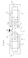
- Radio-frequency detection system 1 comprises a radio-frequency detection device 2 and a radio-frequency detection device 4.
- Radio-frequency detection device 2 has an equalising element 3 and an aerial L 1 connected to equalising element 3.
- Equalising element 3 is connected at the input side to a transmitter 10 for generating a radio-frequency signal with a radio-frequency current.
- Radio-frequency detection device 4 comprises an equalising element 5 and a transmitter 12 for generating a radio-frequency signal with a radio-frequency current.
- Equalising element 5 is connected at the output side to an aerial L 2 and at the input side to transmitter 12.
- Radio-frequency detection system 1 also comprises a compensating element L 3 .
- Compensating element L 3 is designed as an inductor, whereby a first connection of compensating element L 3 is connected via a connecting node 15, in particular in the region of a first end of aerial L 1 , to aerial L 1 .
- a second connection of compensating element L 3 is connected via a connecting node 13, in particular in the region of a first end of aerial L 2 , to aerial L 2 .
- Aerials L 1 and L 2 are connected galvanically to one another in each case at least indirectly.
- aerial L 1 is connected via a connecting node 11, a connecting line 7 and a connecting node 9 to aerial L 2 .
- Transmitter 10 is designed to generate a radio-frequency signal and to send the latter via equalising element 3 to aerial L 1 .
- a radio-frequency current of the radio-frequency signal sent to aerial L 1 is denoted by i 1 .
- a voltage U 1 generated by induction thus drops over aerial L 1 .
- the magnetic near field generated by aerial L 1 forms a detection range for a radio-frequency marking and permeates the detection range of aerial L 2 .
- Aerials L 1 and L 2 are now inductively coupled together.
- a mutual inductance M is also represented, which characterises an impedance of the magnetic flux which couples aerial L 1 and aerial L 2 to one another.
- the coupling magnetic field permeating aerial L 2 generates a parasitic current U M proportional to mutual inductance M.
- radio-frequency detection devices 2 and 4 are each tuned to the same resonance frequency via equalising elements 3 and 5 respectively, a field increase can be formed in the detection range of aerial L 2 , said increase being generated by parasitic voltage U M .
- a radio-frequency marking can thus be detected to a greater extent in the detection range of aerial L 2 , since field lines, which without the presence of aerial L 2 run in the edge region of the detection range of aerial L 1 , are concentrated in the range of aerial L 2 and thus form a locally increased magnetic field strength.
- Radio-frequency detection device 2 is designed to detect a transmitting power outputted by transmitter 10, in particular by means of a demodulator, and thus to detect a change in the magnetic near field generated by aerial L 1 , said change being brought about by load modulation of a radio-frequency marking.
- aerial L 1 By means of aerial L 1 , coupling element L 3 connected via connecting node 15 and aerial L 2 connected via connecting node 13 and connecting line 7 connected via connecting nodes 9 and 11 to aerial L 1 , a mesh is formed in which a current i 3 flows as part of the radio-frequency signal emitted by transmitter 10.
- Mesh current i 3 thus formed generates in aerial L 2 , in particular by self-induction, an active induction voltage U A , which is directed in the same direction as a voltage U 2 dropping over aerial L 2 .
- Voltage U 2 thus results as the sum of a self-induction voltage, generated by current i 2 , a voltage U M generated by mutual inductance M as a function of current i 1 and voltage U A generated by induction of current i 3 in aerial L 2 .
- Current i 3 generates in aerial L 2 a magnetic opposing field, which suppresses or weakens the magnetic near field of aerial L 1 in the detection range of aerial L 2 .
- Radio-frequency detection system 20 comprises a radio-frequency detection device 22, a radio-frequency detection device 24 and a radio-frequency detection device 30.
- Radio-frequency detection device 22 comprises an aerial 23
- radio-frequency detection device 24 comprises an aerial 25
- radio-frequency detection device 30 comprises an aerial 27.
- Radio-frequency detection device 22 comprises a transmitter 26, which is connected at the output side to aerial 23.
- Radio-frequency detection device 24 comprises a transmitter 28, which is connected at the output side to aerial 25.
- Radio-frequency detection device 30 comprises a transmitter 32, which is connected at the output side to aerial 27.
- Transmitters 26, 28 and 32 are each designed to generate a radio-frequency current.
- Aerials 23, 25 and 27 are each designed, depending on a radio-frequency current flowing through the aerial, to generate a correspondingly formed magnetic near field with a detection range for a radio-frequency marking.
- a detection range is formed at least in loop sections corresponding to the shape of a torus and encloses the aerial at least in sections.
- a field line 51 of the magnetic near field generated by aerial 23 is represented.
- a radio-frequency marking 60 is arranged in the detection range of aerial 23. Radio-frequency marking 60 is designed for the load modulation of a magnetic near field. The magnetic near field generated by aerial 23 experiences, through the modulation thus generated, a change in flux which brings about a reaction on transmitter 26.
- Transmitter 26 is connected to a detection device 33, which has a demodulator.
- Detection device 33 is designed to detect the load modulation of the magnetic near field generated by radio-frequency marking 60 and to generate a marking signal, which corresponds to marking information represented by radio-frequency marking 60.
- Radio-frequency marking 61 which is located in the detection range of aerial 25, is also represented. Radio-frequency marking 61 is also located in the detection range of aerial 23, so that the magnetic near field generated by aerial 23 could also be modulated by radio-frequency marking 61. A field line 52 of the detection range of aerial 25 is also represented.
- Radio-frequency marking 61 is detected in the case of a radio-frequency current generated by transmitter 28, which current flows through aerial 25.
- Field line 52 also passes through the detection range of aerial 23, so that radio-frequency marking 60 arranged in the detection range of aerial 23 could also be detected by aerial 25.
- Transmitter 28 is connected to a detection device 29, which is designed corresponding to detection device 33.
- Radio-frequency detection device 22 has a connection 34 for the connection to a compensating element, which is connected to transmitter 26 and to a first connection of aerial 23.
- Connection 34 is connected via a compensating element 45 to a connection 35 for the connection of a compensating element of radio-frequency detection device 24.
- Connection 35 is connected to a first connection of aerial 25.
- a second connection of aerial 25 is connected to a connection 39 of radio-frequency detection device 24, the connection 39 being connected to a common potential of radio-frequency detection system 20.
- a second connection of aerial 23 is connected to a connection 43 of radio-frequency detection device 22.
- Connection 43 is connected to the common potential of radio-frequency detection system 20.
- Compensating element 45 comprises an inductor.
- a radio-frequency current generated by transmitter 26 can thus flows at least partially via connection 34, compensating element 45, connection 35, through aerial 25 and via connection 39, also via the common potential and via connection 43 to transmitter 26.
- the current flowing via compensating element 45 and aerial 25 generates a magnetic opposing field in the detection region of aerial 25, which can weaken or suppress the magnetic near field generated by aerial 23 in the detection range of aerial 25.
- Radio-frequency marking 61, which is located in the detection range of aerial 25, cannot therefore be detected by the magnetic near field generated by aerial 23.
- Radio-frequency marking 60 arranged in the detection range of aerial 23 could thus also be detected by the magnetic near field of aerial 25.
- Aerial 23 is connected via connection 35 and compensating element 45 via connection 34 and via the common potential via connections 39 and 43 to transmitter 28, so that a radio-frequency current generated by transmitter 28 flows through aerial 23.
- Radio-frequency marking 60 cannot therefore also be detected by aerial 25.
- Radio-frequency detection device 30 has a connection 37, which is connected to a first connection of aerial 27.
- a second connection of aerial 27 is connected to a connection 41, which is connected to the common potential of radio-frequency detection system 20.
- Connection 37 is connected to connection 34 by means of compensating element 47.
- Connection 35 is connected to connection 37 by means of compensating element 49.
- a radio-frequency current generated by transmitter 26 can flow at least partially via connection 34 and via compensating element 47 and also via connection 37 through aerial 27 and can weaken or suppress there a part of the magnetic near field generated by aerial 23, a field line 53 of which is represented by way of example.
- a radio-frequency marking 62 which is located in the detection range of aerial 27, is also represented.
- a field line 55 of the magnetic near field generated by aerial 25 runs through the detection range of aerial 27.
- a radio-frequency current generated by transmitter 28 can send, for compensation of the magnetic near field of aerial 25 in the range of aerial 27, a radio-frequency current via connection 35, compensating element 49 and connection 37 across aerial 27 and can thus weaken or suppress the magnetic near field of aerial 25 in the range of aerial 27.
- An aerial can act as an active or as a passive aerial in a radio-frequency detection system in the manner described above.
- An embodiment of a radio-frequency detection system wherein a plurality of aerials or all the aerials are active is also conceivable.
Landscapes
- Engineering & Computer Science (AREA)
- Computer Networks & Wireless Communication (AREA)
- Signal Processing (AREA)
- Near-Field Transmission Systems (AREA)
- Measuring Frequencies, Analyzing Spectra (AREA)
- Measuring Magnetic Variables (AREA)
- Measuring And Recording Apparatus For Diagnosis (AREA)
- Geophysics And Detection Of Objects (AREA)
Applications Claiming Priority (1)
| Application Number | Priority Date | Filing Date | Title |
|---|---|---|---|
| DE102006041914A DE102006041914A1 (de) | 2006-09-07 | 2006-09-07 | Radiofrequenzerfassungssystem für eine medizinische Vorrichtung und Verfahren |
Publications (3)
| Publication Number | Publication Date |
|---|---|
| EP1898533A2 true EP1898533A2 (fr) | 2008-03-12 |
| EP1898533A3 EP1898533A3 (fr) | 2008-05-28 |
| EP1898533B1 EP1898533B1 (fr) | 2010-08-25 |
Family
ID=38698892
Family Applications (1)
| Application Number | Title | Priority Date | Filing Date |
|---|---|---|---|
| EP07253409A Not-in-force EP1898533B1 (fr) | 2006-09-07 | 2007-08-29 | Système de détection de radio-fréquence pour appareil médical et procédé |
Country Status (5)
| Country | Link |
|---|---|
| US (1) | US8099044B2 (fr) |
| EP (1) | EP1898533B1 (fr) |
| JP (1) | JP5038827B2 (fr) |
| CN (1) | CN101141026B (fr) |
| DE (2) | DE102006041914A1 (fr) |
Families Citing this family (5)
| Publication number | Priority date | Publication date | Assignee | Title |
|---|---|---|---|---|
| DE102006042346A1 (de) * | 2006-09-08 | 2008-03-20 | Dräger Medical AG & Co. KG | Medizinische Vorrichtung mit einer Radiofrequenzerfassungsvorrichtung |
| JP5674264B2 (ja) * | 2008-08-26 | 2015-02-25 | 株式会社マトリックス | タグの三次元位置検出システム |
| US9728997B2 (en) | 2011-09-21 | 2017-08-08 | Samsung Electronics Co., Ltd. | Wireless power transmission system |
| DE102013006701A1 (de) | 2013-04-18 | 2014-10-23 | Dräger Medical GmbH | Verfahren zum Betrieb eines Medizingeräts und nach dem Verfahren arbeitendes Medizingerät |
| DE102017006001A1 (de) | 2017-06-26 | 2018-12-27 | Dräger Safety AG & Co. KGaA | Mess- oder Medizingerät sowie Verfahren zum Betrieb eines Mess- oder Medizingeräts |
Family Cites Families (9)
| Publication number | Priority date | Publication date | Assignee | Title |
|---|---|---|---|---|
| US4751516A (en) * | 1985-01-10 | 1988-06-14 | Lichtblau G J | Antenna system for magnetic and resonant circuit detection |
| US5302901A (en) | 1991-08-26 | 1994-04-12 | U.S. Philips Corporation | Magnetic resonance apparatus comprising decoupled receiver coils |
| US6208235B1 (en) * | 1997-03-24 | 2001-03-27 | Checkpoint Systems, Inc. | Apparatus for magnetically decoupling an RFID tag |
| JP4388442B2 (ja) * | 2004-09-08 | 2009-12-24 | オリンパス株式会社 | 位置検出装置および被検体内導入システム |
| US7501955B2 (en) * | 2004-09-13 | 2009-03-10 | Avery Dennison Corporation | RFID device with content insensitivity and position insensitivity |
| FR2875975B1 (fr) * | 2004-09-27 | 2009-05-15 | Commissariat Energie Atomique | Dispositif sans contact de prorection de la vie privee |
| WO2006097760A1 (fr) * | 2005-03-18 | 2006-09-21 | Innovision Research & Technology Plc | Dispositif, appareil et systeme de communication |
| DE202005013779U1 (de) * | 2005-06-09 | 2006-01-26 | Acg Identification Technologies Gmbh | Vorrichtung zur Kommunikation mit Transpondern über Nahfeld-Antennen |
| EP1891748A1 (fr) * | 2005-06-14 | 2008-02-27 | Nokia Corporation | Multiplication d'etiquettes |
-
2006
- 2006-09-07 DE DE102006041914A patent/DE102006041914A1/de not_active Withdrawn
-
2007
- 2007-08-23 US US11/843,878 patent/US8099044B2/en not_active Expired - Fee Related
- 2007-08-29 EP EP07253409A patent/EP1898533B1/fr not_active Not-in-force
- 2007-08-29 DE DE602007008657T patent/DE602007008657D1/de active Active
- 2007-09-07 CN CN2007101536054A patent/CN101141026B/zh not_active Expired - Fee Related
- 2007-09-07 JP JP2007233278A patent/JP5038827B2/ja not_active Expired - Fee Related
Non-Patent Citations (1)
| Title |
|---|
| None |
Also Published As
| Publication number | Publication date |
|---|---|
| DE102006041914A1 (de) | 2008-03-27 |
| EP1898533A3 (fr) | 2008-05-28 |
| US8099044B2 (en) | 2012-01-17 |
| JP5038827B2 (ja) | 2012-10-03 |
| EP1898533B1 (fr) | 2010-08-25 |
| CN101141026A (zh) | 2008-03-12 |
| US20080064445A1 (en) | 2008-03-13 |
| DE602007008657D1 (de) | 2010-10-07 |
| JP2008064762A (ja) | 2008-03-21 |
| CN101141026B (zh) | 2011-06-08 |
Similar Documents
| Publication | Publication Date | Title |
|---|---|---|
| EP1898533B1 (fr) | Système de détection de radio-fréquence pour appareil médical et procédé | |
| JP4584082B2 (ja) | リーダ・ライタ及び通信方法 | |
| JP4827853B2 (ja) | 距離指示システムおよび方法 | |
| EP0579332B1 (fr) | Système de detection électromagnétique | |
| US20110187321A1 (en) | Wireless charging system for vehicle | |
| US9812254B2 (en) | Wireless power feeder | |
| CN102645673A (zh) | 感应邻近传感器 | |
| DE102008056930A1 (de) | Drahtlose Funkidentifikation | |
| EP3273609A1 (fr) | Dispositif de communication et procédé de communication | |
| EP2179512B1 (fr) | Dispositif de transmission sans contact de la puissance et d'un signal de données | |
| US20180131241A1 (en) | Device for transmitting energy and data and method for operating such device | |
| JP2009527954A5 (fr) | ||
| US20140124628A1 (en) | Railway circuit for sending signalling information along a railway line to a vehicle travelling along the railway line | |
| EP2710745B1 (fr) | Procédé et dispositif de communication et de transmission d'énergie au moyen d'un transformateur | |
| KR101784683B1 (ko) | 효율적인 무선전력 전송을 이용한 열차위치검지시스템 및 그 방법 | |
| JP2022513867A (ja) | アンテナ配置構造及びアンテナ配置構造の使用方法 | |
| US9014625B2 (en) | Method and apparatus for generating dedicated data channels in inductive coupled RFID systems using band-pass modulation | |
| CN101151619A (zh) | 具有天线的rfid读取器及其操作方法 | |
| CN101160589A (zh) | Rfid收发机单元 | |
| JP4233697B2 (ja) | データキャリア用質問機 | |
| NL9202158A (nl) | Identificatiesysteem volgens de transmissiemethode. | |
| JP4522765B2 (ja) | タイヤ情報検出装置 | |
| JP4666506B2 (ja) | 列車選別装置 | |
| JP5657312B2 (ja) | 電力線搬送波送受信装置 | |
| JPH09181656A (ja) | データ送受信システムおよびデータ送受信方法 |
Legal Events
| Date | Code | Title | Description |
|---|---|---|---|
| PUAI | Public reference made under article 153(3) epc to a published international application that has entered the european phase |
Free format text: ORIGINAL CODE: 0009012 |
|
| 17P | Request for examination filed |
Effective date: 20070907 |
|
| AK | Designated contracting states |
Kind code of ref document: A2 Designated state(s): AT BE BG CH CY CZ DE DK EE ES FI FR GB GR HU IE IS IT LI LT LU LV MC MT NL PL PT RO SE SI SK TR |
|
| AX | Request for extension of the european patent |
Extension state: AL BA HR MK YU |
|
| PUAL | Search report despatched |
Free format text: ORIGINAL CODE: 0009013 |
|
| AK | Designated contracting states |
Kind code of ref document: A3 Designated state(s): AT BE BG CH CY CZ DE DK EE ES FI FR GB GR HU IE IS IT LI LT LU LV MC MT NL PL PT RO SE SI SK TR |
|
| AX | Request for extension of the european patent |
Extension state: AL BA HR MK RS |
|
| RIN1 | Information on inventor provided before grant (corrected) |
Inventor name: STEEGER, MARKUS Inventor name: SCHERMEIER, OLAF |
|
| AKX | Designation fees paid |
Designated state(s): DE FR GB SE |
|
| GRAP | Despatch of communication of intention to grant a patent |
Free format text: ORIGINAL CODE: EPIDOSNIGR1 |
|
| GRAS | Grant fee paid |
Free format text: ORIGINAL CODE: EPIDOSNIGR3 |
|
| GRAA | (expected) grant |
Free format text: ORIGINAL CODE: 0009210 |
|
| AK | Designated contracting states |
Kind code of ref document: B1 Designated state(s): DE FR GB SE |
|
| REG | Reference to a national code |
Ref country code: GB Ref legal event code: FG4D |
|
| REF | Corresponds to: |
Ref document number: 602007008657 Country of ref document: DE Date of ref document: 20101007 Kind code of ref document: P |
|
| REG | Reference to a national code |
Ref country code: SE Ref legal event code: TRGR |
|
| REG | Reference to a national code |
Ref country code: DE Ref legal event code: R081 Ref document number: 602007008657 Country of ref document: DE Owner name: DRAEGERWERK AG CO. KGAA, DE Free format text: FORMER OWNER: DRAEGER MEDICAL AG CO. KG, 23558 LUEBECK, DE Effective date: 20110201 Ref country code: DE Ref legal event code: R081 Ref document number: 602007008657 Country of ref document: DE Owner name: DRAEGER MEDICAL GMBH, DE Free format text: FORMER OWNER: DRAEGER MEDICAL AG & CO. KG, 23558 LUEBECK, DE Effective date: 20110201 Ref country code: DE Ref legal event code: R081 Ref document number: 602007008657 Country of ref document: DE Owner name: DRAEGERWERK AG & CO. KGAA, DE Free format text: FORMER OWNER: DRAEGER MEDICAL AG & CO. KG, 23558 LUEBECK, DE Effective date: 20110201 |
|
| PLBE | No opposition filed within time limit |
Free format text: ORIGINAL CODE: 0009261 |
|
| STAA | Information on the status of an ep patent application or granted ep patent |
Free format text: STATUS: NO OPPOSITION FILED WITHIN TIME LIMIT |
|
| 26N | No opposition filed |
Effective date: 20110526 |
|
| REG | Reference to a national code |
Ref country code: DE Ref legal event code: R097 Ref document number: 602007008657 Country of ref document: DE Effective date: 20110526 |
|
| REG | Reference to a national code |
Ref country code: FR Ref legal event code: PLFP Year of fee payment: 9 |
|
| REG | Reference to a national code |
Ref country code: DE Ref legal event code: R081 Ref document number: 602007008657 Country of ref document: DE Owner name: DRAEGERWERK AG CO. KGAA, DE Free format text: FORMER OWNER: DRAEGER MEDICAL GMBH, 23558 LUEBECK, DE Ref country code: DE Ref legal event code: R081 Ref document number: 602007008657 Country of ref document: DE Owner name: DRAEGERWERK AG & CO. KGAA, DE Free format text: FORMER OWNER: DRAEGER MEDICAL GMBH, 23558 LUEBECK, DE |
|
| REG | Reference to a national code |
Ref country code: FR Ref legal event code: TP Owner name: DRAGERWERK AG & CO. KGAA, DE Effective date: 20160226 Ref country code: FR Ref legal event code: CD Owner name: DRAGERWERK AG & CO. KGAA, DE Effective date: 20160226 |
|
| REG | Reference to a national code |
Ref country code: FR Ref legal event code: PLFP Year of fee payment: 10 |
|
| REG | Reference to a national code |
Ref country code: FR Ref legal event code: PLFP Year of fee payment: 11 |
|
| REG | Reference to a national code |
Ref country code: GB Ref legal event code: 732E Free format text: REGISTERED BETWEEN 20180215 AND 20180221 |
|
| REG | Reference to a national code |
Ref country code: FR Ref legal event code: PLFP Year of fee payment: 12 |
|
| PGFP | Annual fee paid to national office [announced via postgrant information from national office to epo] |
Ref country code: SE Payment date: 20190826 Year of fee payment: 13 Ref country code: FR Payment date: 20190822 Year of fee payment: 13 |
|
| PGFP | Annual fee paid to national office [announced via postgrant information from national office to epo] |
Ref country code: GB Payment date: 20190827 Year of fee payment: 13 |
|
| REG | Reference to a national code |
Ref country code: SE Ref legal event code: EUG |
|
| GBPC | Gb: european patent ceased through non-payment of renewal fee |
Effective date: 20200829 |
|
| PG25 | Lapsed in a contracting state [announced via postgrant information from national office to epo] |
Ref country code: SE Free format text: LAPSE BECAUSE OF NON-PAYMENT OF DUE FEES Effective date: 20200830 |
|
| PG25 | Lapsed in a contracting state [announced via postgrant information from national office to epo] |
Ref country code: FR Free format text: LAPSE BECAUSE OF NON-PAYMENT OF DUE FEES Effective date: 20200831 |
|
| PG25 | Lapsed in a contracting state [announced via postgrant information from national office to epo] |
Ref country code: GB Free format text: LAPSE BECAUSE OF NON-PAYMENT OF DUE FEES Effective date: 20200829 |
|
| PGFP | Annual fee paid to national office [announced via postgrant information from national office to epo] |
Ref country code: DE Payment date: 20220630 Year of fee payment: 16 |
|
| REG | Reference to a national code |
Ref country code: DE Ref legal event code: R079 Ref document number: 602007008657 Country of ref document: DE Free format text: PREVIOUS MAIN CLASS: H04B0005020000 Ipc: H04B0005480000 |
|
| REG | Reference to a national code |
Ref country code: DE Ref legal event code: R119 Ref document number: 602007008657 Country of ref document: DE |
|
| PG25 | Lapsed in a contracting state [announced via postgrant information from national office to epo] |
Ref country code: DE Free format text: LAPSE BECAUSE OF NON-PAYMENT OF DUE FEES Effective date: 20240301 |