EP1898621A1 - Dispositif périphérique de traitement vocal, et système de téléphonie ip - Google Patents
Dispositif périphérique de traitement vocal, et système de téléphonie ip Download PDFInfo
- Publication number
- EP1898621A1 EP1898621A1 EP06745844A EP06745844A EP1898621A1 EP 1898621 A1 EP1898621 A1 EP 1898621A1 EP 06745844 A EP06745844 A EP 06745844A EP 06745844 A EP06745844 A EP 06745844A EP 1898621 A1 EP1898621 A1 EP 1898621A1
- Authority
- EP
- European Patent Office
- Prior art keywords
- peripheral device
- speech processing
- voip call
- information processing
- processing peripheral
- Prior art date
- Legal status (The legal status is an assumption and is not a legal conclusion. Google has not performed a legal analysis and makes no representation as to the accuracy of the status listed.)
- Granted
Links
- 238000012545 processing Methods 0.000 title claims abstract description 141
- 230000002093 peripheral effect Effects 0.000 title claims abstract description 106
- 230000010365 information processing Effects 0.000 claims abstract description 26
- 230000005236 sound signal Effects 0.000 claims abstract description 23
- 238000004891 communication Methods 0.000 claims abstract description 11
- 230000006870 function Effects 0.000 claims description 16
- 230000006835 compression Effects 0.000 description 16
- 238000007906 compression Methods 0.000 description 16
- 238000010586 diagram Methods 0.000 description 15
- 230000000694 effects Effects 0.000 description 5
- 238000012546 transfer Methods 0.000 description 4
- 230000005856 abnormality Effects 0.000 description 3
- 238000000034 method Methods 0.000 description 3
- 238000006243 chemical reaction Methods 0.000 description 2
- 238000010521 absorption reaction Methods 0.000 description 1
- 239000000872 buffer Substances 0.000 description 1
- 230000003139 buffering effect Effects 0.000 description 1
- 239000000470 constituent Substances 0.000 description 1
- 238000012217 deletion Methods 0.000 description 1
- 230000037430 deletion Effects 0.000 description 1
- 238000003780 insertion Methods 0.000 description 1
- 230000037431 insertion Effects 0.000 description 1
Images


Classifications
-
- H—ELECTRICITY
- H04—ELECTRIC COMMUNICATION TECHNIQUE
- H04M—TELEPHONIC COMMUNICATION
- H04M1/00—Substation equipment, e.g. for use by subscribers
- H04M1/253—Telephone sets using digital voice transmission
- H04M1/2535—Telephone sets using digital voice transmission adapted for voice communication over an Internet Protocol [IP] network
-
- H—ELECTRICITY
- H04—ELECTRIC COMMUNICATION TECHNIQUE
- H04M—TELEPHONIC COMMUNICATION
- H04M1/00—Substation equipment, e.g. for use by subscribers
- H04M1/60—Substation equipment, e.g. for use by subscribers including speech amplifiers
- H04M1/6033—Substation equipment, e.g. for use by subscribers including speech amplifiers for providing handsfree use or a loudspeaker mode in telephone sets
- H04M1/6041—Portable telephones adapted for handsfree use
- H04M1/6058—Portable telephones adapted for handsfree use involving the use of a headset accessory device connected to the portable telephone
Definitions
- the present invention relates to a speech processing peripheral device and an IP telephone system.
- the present invention can be applied to a peripheral device of a personal computer (PC), wherein the peripheral device implements an IP telephone function together with a program on the PC, and can be applied to an IP telephone system using the peripheral device.
- PC personal computer
- IP telephone for enabling a telephone conversation through an IP network
- a type of IP telephone that implements IP telephone functions such as call processing and audio signal processing by means of software on the PC is referred to as a softphone (see Non-patent document 1).
- the softphone has many advantages over an IP telephone set (hereafter referred to as a hardphone) implemented by the conventional hardware device, in terms of terminal cost, linkage with other services or functions, and the like.
- Non-patent document 1 Nikkei Communications, "IP telephone ONLINE”, searched through Internet on May 16, 2005, "http://itpro.nikkeibp.co.jp/free/NCC/denwa/20050211/39/ ".
- the softphone has the following problems.
- the first problem is that it is hard to maintain a constant quality of an IP telephone service because the speech quality depends on the specifications of the PC (an operational clock frequency and internal A-D/D-A characteristics) and the number of applications running in parallel during a telephone conversation.
- the second problem is that the IP telephone function is disabled if out-of-control, power-down, or the like occurs in the PC. Since the days of using an analog telephone, the power supply of a telephone set has been transparent to users. Accordingly, a user feels awkward to become aware of the power supply of the telephone set.
- IP telephone system which has both convenience of the softphone and durability of the hardphone and is inexpensive, and a device for the IP telephone system.
- a speech processing peripheral device executes a call control program, the speech processing peripheral device being a peripheral device of an information processing device functioning as a call controller, the speech processing peripheral device being connected to the information processing device.
- the speech processing peripheral device includes (1) a host connection means which sends/receives an audio signal to/from the information processing device, and (2) a speech processing means which executes speech processing in IP telephone communication.
- an IP telephone system includes an information processing device or devices which execute a call control program and functions as a call controller, and the speech processing peripheral device according to the present invention, which is connected to the information processing device.
- an information processing device provides a call control function by software
- a speech processing peripheral device provides a speech processing function by hardware. Accordingly, an inexpensive IP telephone system having both convenience of the softphone and durability of the hardphone can be provided.
- IP telephone system 1 IP telephone system; 10 speech processing peripheral device; 11 A-D/D-A section; 12 audio compression/expander; 13 IP packet processor; 14, 61 to 63 USB control section; 15 on-hook/off-hook instruction section; 16 headset direct-connection instruction section; 17 USB memory; 20, 20SBY PC (VoIP call controller); 30 USB connector; 40 headset; 50 IP network; 60 call channel selection device; 64 connection controller; 65 button detector.
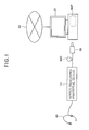
- FIG. 1 is a block diagram showing a whole configuration of the IP telephone system of the first embodiment.
- an IP telephone system 1 of the first embodiment includes a speech processing peripheral device 10 of the first embodiment and a PC 20.
- the speech processing peripheral device 10 has a USB connector 30 at an end of a cable 30C fixed (or detachably connected) to the speech processing peripheral device 10, for example, and can be connected to the PC 20 through the USB connector 30.
- the speech processing peripheral device 10 has a headset (or a handset) 40 fixed (or detachably connected) to the speech processing peripheral device 10.
- the PC 20 is connected to an IP network 50 through a LAN (not shown in the drawing) and the like.
- the VoIP call control is mainly performed by the PC 20, and the speech processing is mainly performed by the speech processing peripheral device 10.
- the PC 20 executes a VoIP call control program 20P, thereby performing the VoIP call control other than speech processing.
- the VoIP call control program 20P is an application program of an existing softphone with a routine for speech processing (speech processing during a telephone conversation) excluded and with a routine for interfacing with the speech processing peripheral device 10 added.
- the VoIP call control program 20P performs connection processing and disconnection processing in IP telephone communication, sends/receives instructions and data to/from the speech processing peripheral device 10, performs user interface processing, and performs other processing.
- the VoIP call control program 20P starts when a user clicks on the file name, and this makes the PC 20 possible to operate as a VoIP call controller.
- the VoIP call control program 20P may be configured not to be started directly from a VoIP call control program memory 17 but to be installed in a hard disk or the like in the PC 20 when a user clicks on the file name and then to be started from the hard disk or the like.
- the speech processing peripheral device 10 has a configuration as will be described later in detail and exclusively performs speech processing of the IP telephone function.
- a part for performing speech processing is configured by hardware.
- Call control is suitable for processing by the software.
- an application for an address-book file for allowing an outgoing call to be sent directly from an address-book file can be easily linked with the VoIP call control program 20P.
- speech processing is suitable for processing by the hardware.
- the VoIP call control is mainly performed by the PC 20 (the CPU executes the VoIP call control program 20P), and the speech processing is mainly performed by the speech processing peripheral device 10.
- the PC 20, in which the VoIP call control program 20P is functioning is also referred to as a VoIP call controller 20.
- FIG. 2 is a block diagram showing an internal configuration of the speech processing peripheral device 10.
- the speech processing peripheral device 10 includes an A-D/D-A section 11, an audio compression/expander 12, an IP packet processor 13, a USB control section 14, an on-hook/off-hook instruction section 15, a headset direct-connection instruction section 16, a VoIP call control program memory 17, and so on.
- the A-D/D-A section 11 converts an analog audio signal from a microphone (not shown in the drawing) of the headset 40 to a digital audio signal and sends the converted signal to the audio compression/expander 12. Also, the A-D/D-A section 11 converts a digital audio signal from the audio compression/expander 12 to an analog audio signal and sends the converted signal to a speaker (not shown in the drawing) of the headset 40.
- the audio compression/expander 12 compression-encodes the digital audio signal to generate encoded audio data and sends the encoded audio data to the IP packet processor 13. Also, the audio compression/expander 12 expands encoded audio data (compression-encoded data) supplied from the IP packet processor 13, decodes the encoded audio data to generate a digital audio signal, and sends the digital audio signal to the A-D/D-A section 11.
- the IP packet processor 13 converts the encoded audio data supplied from the audio compression/expander 12 to IP packets (i.e., assembles IP packets) to output the IP packets to the USB control section 14. Also, the IP packet processor 13 converts IP packets outputted from the USB control section 14 to encoded audio data (i.e., disassembles IP packets) to supply the encoded audio data to the audio compression/expander 12.
- the IP packet processor 13 includes a part for buffering processing of the received call data and a part for deletion/insertion processing (restoration processing of fluctuation absorption and delay), for example.
- the USB control section 14 controls data transfer with the side of the VoIP call controller 20.
- the USB control section 14 mainly works for data transfer while the IP telephone is in a telephone conversation state.
- the USB control section 14 converts the IP packets supplied from the IP packet processor 13 to a USB data signal and transfers the USB data signal to the VoIP call controller 20, and sends the IP packets transferred as a USB data signal from the VoIP call controller 20 to the IP packet processor 13.
- the on-hook/off-hook instruction section 15 includes an off-hook button and an on-hook button, for example, and is used for entering an off-hook instruction of a user for an incoming call, an on-hook instruction of a user for ending a telephone conversation, and the like.
- the on-hook/off-hook instruction section 15 is connected to the USB control section 14 and sends an on-hook instruction or an off-hook instruction via the USB control section 14 to the VoIP call controller 20.
- the on-hook/off-hook instruction section 15 may be a device for receiving only one of the on-hook instruction and the off-hook instruction.
- the on-hook/off-hook instruction section may be provided not in the speech processing peripheral device 10 but in the PC (VoIP call controller) 20 alone.
- the headset direct-connection instruction section 16 is a device used for entering instructions for causing the speech processing peripheral device 10 to operate as if the headset 40 and the PC (VoIP call controller) 20 are connected substantially directly.
- a signal from the PC 20 is transmitted to the A-D/D-A section 11 by a function as a hub of the USB control section 14, and is converted to an analog signal to be supplied to the speaker of the headset 40.
- a signal from the microphone of the headset 40 is converted to a digital signal by the A-D/D-A section 11, and then sent from the USB control section 14 to the PC 20.
- the function can be executed in a state as if the USB headset is connected to the PC 20, by entering instructions by using the headset direct-connection instruction section 16.
- the VoIP call control program memory 17 stores a VoIP call control program 20P to be supplied to the PC 20.
- the VoIP call control program memory 17 stores a VoIP call control program 20P to be supplied to the PC 20.
- the USB connector 30 provided at an end of the cable extending from the speech processing peripheral device 10 is inserted into the PC 20 in the power-on state, which is not shown in the drawing, attribute information and the like is sent/received between the PC 20 and the speech processing peripheral device 10 in accordance with the USB protocol, and the PC 20 recognizes that the speech processing peripheral device 10 is connected and is brought to a state for supplying a power.
- the processing at this time is the same as the processing based on a normal sequence for USB devices.
- the speech processing peripheral device 10 notifies the existence of a file of the VoIP call control program stored in the VoIP call control program memory 17 in substantially the same way as a case where the USB memory is used.
- the PC 20 causes the file name of the VoIP call control program to be displayed. When a user clicks on the displayed file name, the VoIP call control program 20P is installed in the PC 20, and the PC 20 is enabled to function as the VoIP call controller.
- the VoIP call control program 20P when the VoIP call control program 20P is active, a user inputs a far-end telephone number from a keyboard or the like and operates a key to instruct an outgoing call on the keyboard (S1). At this time, the VoIP call controller 20 sends/receives a signal for calling to/from the side of the IP network 50 (S2). The processing at this time is substantially the same as the processing of the existing softphone. The signal is sent/received to/from the side of the IP network 50 in accordance with the SIP protocol, for example.
- the VoIP call controller 20 When the VoIP call controller 20 receives a notification that the far-end terminal is in a called state, the VoIP call controller 20 performs processing to cause a RBT to sound from the speaker of the headset 40 (S3, S4).
- the tone is a RBT signal.
- the VoIP call controller 20 includes a tone generator for outputting a RBT signal as a digital signal, and sends the RBT signal as a serial signal to the speech processing peripheral device 10.
- the USB control section 14 of the speech processing peripheral device 10 that receives the RBT signal, sends the received RBT signal to the A-D/D-A section 11, causes the received RBT signal to be converted to an analog signal by the A-D/D-A section 11, and causes the sound to be outputted from the speaker of the headset 40.
- the VoIP call controller 20 includes a tone generator for outputting a compression-encoded RBT signal, and the VoIP call controller 20 turns the compression-encoded RBT signal into packets (such as RTP packets) to send the packets to the speech processing peripheral device 10.
- the received packets of a RBT outputted form the USB control section 14 of the speech processing peripheral device 10 are sent to the IP packet processor 13, which disassembles the packets, the compression-encoded data supplied from the IP packet processor 13 is expanded and decoded to a RBT signal by the audio compression/expander 12, the expanded decoded signal is converted to an analog signal by the A-D/D-A section 11, and the sound is outputted from the speaker of the headset 40.
- the speech processing peripheral device 10 includes a tone generator (not shown in FIG. 2 ) for generating a RBT signal as a digital signal, and the VoIP call controller 20 sends tone generation instructions specifying a type of tone (a RBT in this description) to the speech processing peripheral device 10.
- the tone generator which is not shown in the drawing, sends a RBT signal as a digital signal to the A-D/D-A section 11, causes the A-D/D-A section 11 to convert the RBT signal to an analog signal, and causes the speaker of the headset 40 to output the RBT.
- the VoIP call controller 20 When the VoIP call controller 20 receives a notification from the side of the IP network 50 that the far-end terminal is brought to the off-hook state in reply to the call (S5), it sends data necessary for forming the audio IP packets including the IP address of the far-end terminal and so on, to the speech processing peripheral device 10 (S6, S7).
- the VoIP call controller 20 put itself in such a state that the audio IP packets from the speech processing peripheral device 10 are directly outputted to the side of the IP network 50, and the audio IP packets from the side of the IP network 50 are directly outputted to the speech processing peripheral device 10 (S8).
- the USB control section 14 of the speech processing peripheral device 10 receives the data needed to form the audio IP packets and sends the received data to the IP packet processor 13, which buffers the data.
- the VoIP call controller 20 returns a reception reply to the off-hook notification of the far-end terminal to the side of the IP network 50 (S9) and performs processing to terminate the RBT sound with respect to the speech processing peripheral device 10 (S10).
- a telephone conversation state starts (S11).
- the VoIP call controller 20 confirms that the IP packet from the side of the IP network 50 is an audio IP packet to send the packet to the speech processing peripheral device 10, and also confirms that the IP packet from the speech processing peripheral device 10 is an audio IP packet to send the packet to the side of the IP network 50.
- an analog audio signal from a microphone (not shown) of the headset 40 is converted to a digital audio signal by the A-D/D-A section 11 and is subsequently compression-encoded by the audio compression/expander 12.
- the encoded audio data are converted to audio IP packets by the IP packet processor 13 and transferred from the USB control section 14 to the VoIP call controller 20.
- the audio IP packets transferred from the VoIP call controller 20 are supplied to the IP packet processor 13 through the USB control section 14, the audio IP packets are disassembled and converted to encoded audio data by the IP packet processor 13, the encoded audio data (compression-encoded data) are expanded by the audio compression/expander 12, the obtained digital audio signal is converted to an analog audio signal by the A-D/D-A section 11, and the sound is outputted from the speaker of the headset 40.
- FIG. 4 is a sequence diagram showing operation at the time of an incoming call of the IP telephone system 1 of the first embodiment.
- the PC (VoIP call controller) 20 When receiving a call control IP packet relating to a calling from the side of the IP network 50, the PC (VoIP call controller) 20 starts executing the VoIP call control program 20P as an interrupt service and starts functioning as the VoIP call controller (S20, S21).
- the VoIP call controller 20 confirms that the speech processing peripheral device 10 is ready to reply the calling, such as that it is connected and is not in telephone communication with another party (S22), then performs processing to sound a calling tone from the speaker of the headset 40 (S23), and informs the side of the IP network 50 (far-end terminal) that the VoIP call controller 20 is in a called state (S24).
- the USB control section 14 sends a notification of the off-hook instruction to the VoIP call controller 20 (S25, S26).
- the VoIP call controller 20 sends data required to form the audio IP packets, such as the IP address of the far-end terminal and the like, to the speech processing peripheral device 10 (S27, S28), and brings itself in such a state that the audio IP packets from the speech processing peripheral device 10 are directly output to the side of the IP network 50, and the audio IP packets from the side of the IP network 50 are directly output to the speech processing peripheral device 10 (S29).
- the VoIP call controller 20 returns an off-hook notification to the side of the IP network 50 (far-end terminal) (S30) and performs processing to stop sounding the calling tone with respect to the speech processing peripheral device 10 (S31).
- a telephone conversation state starts (S32).
- FIG. 5 is a sequence diagram showing operation at the time of disconnection in accordance with the on-hook operation on the side of a near-end device of the IP telephone system 1 of the first embodiment.
- the speech processing peripheral device 10 When the on-hook button is operated in the telephone conversation state in the speech processing peripheral device 10, the speech processing peripheral device 10 resets itself, and the USB control section 14 sends a notification of an on-hook instruction to the VoIP call controller 20 (S40 to S42).
- the VoIP call controller 20 After sending a notification of disconnection to the side of the IP network 50 (far-end terminal) (S43), the VoIP call controller 20 waits for a reception reply, and then brings the VoIP call control program 20P into a log-off state (S44).
- FIG. 6 is a sequence diagram showing operation at the time of disconnection in accordance with an on-hook operation on the side of the far-end terminal of the IP telephone system 1 of the first embodiment.
- the VoIP call controller 20 has already confirmed whether the IP packet received from the IP network 50 (far-end terminal) is an audio IP packet or a call control IP packet, but when a call control IP packet notifying the on-hook state (notification of disconnection) is received (S50), it sends reset instructions to the speech processing peripheral device 10 to reset the speech processing peripheral device 10 under control of the USB control section 14 (S51, S52), sends a reception reply to the notification of disconnection to the side of the IP network 50 (far-end terminal) (S53), and brings the VoIP call control program 20P into the log-off state (S54).
- S50 call control IP packet notifying the on-hook state (notification of disconnection)
- the speech processing peripheral device for performing audio signal processing in a telephone conversation state is provided in addition to the PC for performing VoIP call control by software, and the PC just passes the audio signal sent/received between the speech processing peripheral device and the IP network in a telephone conversation state. Therefore, a stable speech quality can be achieved by a relatively small increase in cost, irrespective of the specifications and load state of the PC.
- A-D conversion and D-A conversion of the audio signal is implemented by the external hardware device, so that noise, an echo, and the like can be avoided, a stable speech quality can be achieved independently of the characteristics of the sound board included in the PC.
- the VoIP call control is implemented as an application of the PC, an advantage of the softphone, which is the compatibility with software processing for sending an outgoing call from an address-book file or the like, can be inherited.
- the speech processing peripheral device since the connection between the speech processing peripheral device and the PC is made by USB, the speech processing peripheral device does not need to have power supply and agrees with such a general users' image that the telephone set does not have a power supply.
- FIG. 7 is a block diagram showing a whole configuration of the IP telephone system of the second embodiment. Constituent elements in FIG. 7 which are the same as or correspond to those in FIG. 1 of the first embodiment are assigned the same or corresponding reference symbols.
- an IP telephone system 1A of the second embodiment has a redundant configuration including a VoIP call controller (PC) for active use and a VoIP call controller (PC) for standby use for executing IP telephone communication by using the speech processing peripheral device 10, and the speech processing peripheral device 10 is connected through a call channel selection device 60 to the VoIP call controller (PC) 20 for active use or the VoIP call controller (PC) 20SBY for standby use.
- PC VoIP call controller
- PC VoIP call controller
- the VoIP call controller 20SBY for standby use operates in place of the VoIP call controller 20 for active use only when the VoIP call controller 20 for active use cannot operate.
- a single call controller 20SBY for standby use may be a common standby system for different types of VoIP call controllers 20 for active use (for example, one standby system on one floor). In this case, the VoIP call controller 20SBY for standby use is connected to a plurality of call channel selection devices 60.
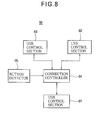
- the call channel selection device 60 has a configuration as shown in detail in FIG. 8 .
- the call channel selection device 60 includes three USB control sections 61 to 63, a connection controller 64, and a button detector 65.
- the first USB control section 61 sends/receives a USB data signal to/from the USB control section 14 of the speech processing peripheral device 10.
- the second USB control section 62 sends/receives a USB data signal to/from the USB control section (not shown in the drawing) of the VoIP call controller 20 for active use.
- the third USB control section 63 sends/receives a USB data signal to/from the USB control section (not shown in the drawing) of the VoIP call controller 20SBY for standby use.
- the connection controller 64 basically connects the speech processing peripheral device 10 and the VoIP call controller 20, i.e., the first USB control section 61 and the second USB control section 62.
- the connection controller 64 connects the speech processing peripheral device 10 and the VoIP call controller 20SBY for standby use, i.e., the first USB control section 61 and the third USB control section 63.
- the connection controller 64 has an outgoing call function for restoring a call from interruption.
- connection controller 64 may control connection to allow communication between the VoIP call controller 20 for active use and the VoIP call controller 20SBY for standby use. Communication between the VoIP call controller 20 for active use and the VoIP call controller 20SBY for standby use may be performed by a LAN.
- the button detector 65 detects a state of buttons pressed by a user to output the state to the connection controller 64. This is used when switching to the standby system is made or when a telephone number is entered to resume a call, for example. (B-2) Operation of Second Embodiment
- the speech processing peripheral device 10 and the VoIP call controller 20 are connected so as to be able to send/receive the USB data signal.
- the VoIP call controller 20SBY for standby use is in a state that it is being connected to the far-end party (the audio data are not being sent nor received).
- the call channel selection device 60 connects the speech processing peripheral device 10 and the VoIP call controller 20SBY for standby use to allow the sending/receiving of the USB data signal, and the VoIP call controller 20SBY for standby use starts sending and receiving the audio data to continue the call.
- the VoIP call controller 20SBY for standby use may not be connected to the far-end party before the VoIP call controller 20 is switched to the VoIP call controller 20SBY for standby use, and the connection (call channel) may be established under control of the call channel selection device 60 after an abnormality in the connection to the VoIP call controller 20 is detected.
- the VoIP call controller 20SBY for standby use operates in substantially the same way as the VoIP call controller 20 to establish the call channel.
- the VoIP call controller 20 and the VoIP call controller 20SBY for standby use may be configured in such a way that they can initiate an outgoing call by using the button information of the call channel selection device 60, so that a call channel with a different far-end terminal can be handled when the call channel is restored.
- the effect is obtained that the speech processing peripheral device 10 allows a call to be made even if the PC operating as the VoIP call controller 20 runs out of control or is powered down.
- the information processing device operating as the VoIP call controller is a PC
- an information processing device having a greater processing capacity than a PC or another information processing device having a smaller processing capacity than a PC can be used as the VoIP call controller operating in accordance with the VoIP call control program.
- the IP packet processor 13 may be provided on the side of the VoIP call controller (PC) 20. Since even in a telephone conversation state, it is judged whether the IP packet is an audio IP packet or a call-control IP packet, the VoIP call controller may have the functions of assembling and disassembling the audio IP packet as well. In this case, encoded audio data would be sent and received between the speech processing peripheral device 10 and the VoIP call controller (PC) 20.
- the audio signal inputted/outputted to/from the side of the headset (handset) is an analog signal
- a USB headset or the like may be used to input/output a digital audio signal through the USB or the like.
- the corresponding USB control section or the like must be added in the speech processing peripheral device 10.
- the audio signal may be sent/received between the headset (handset) 40 and the speech processing peripheral device 10 by radio not by wire.
- the signal sending/receiving between the speech processing peripheral device 10 and the VoIP call controller (PC) 20 may also be performed by radio.
- the connection between the speech processing peripheral device 10 and the VoIP call controller (PC) 20 is not limited to the USB connection.
- the speech processing peripheral device 10 be powered through the USB, but the power may also be separately supplied from a dedicated AC adapter, an internal battery, or the like, for example. It is also desirable that the call channel selection device 60 be powered through the USB, but the power may also be separately supplied from a dedicated AC adapter, an internal battery, or the like, for example.
- the audio compression/expander 12 supports one certain compression encoding method.
- several types of audio compression/expanders may also be provided to support several types of compression encoding methods, and any one of the audio compression/expanders may be selected and used in accordance with information specifying the encoding method contained in the IP packet.
- the speech processing peripheral device may include a built-in speaker and microphone which can be used as a sound input/output device.
- the speech processing peripheral device may include a built-in speaker and microphone which can be used as a sound input/output device, and is provided with a headset or handset which can be enabled only when a jack of the headset or handset is inserted into the speech processing peripheral device.
- the call channel selection device 60 may also be used to connect selectively one of a plurality of VoIP call controllers 20 belonging to the same grade to the speech processing peripheral device 10 (through selection operation, for example).
Landscapes
- Engineering & Computer Science (AREA)
- Signal Processing (AREA)
- Telephonic Communication Services (AREA)
- Telephone Function (AREA)
Applications Claiming Priority (2)
| Application Number | Priority Date | Filing Date | Title |
|---|---|---|---|
| JP2005192004A JP4774831B2 (ja) | 2005-06-30 | 2005-06-30 | 音声処理周辺装置及びip電話システム |
| PCT/JP2006/308985 WO2007004351A1 (fr) | 2005-06-30 | 2006-04-28 | Dispositif périphérique de traitement vocal, et système de téléphonie ip |
Publications (3)
| Publication Number | Publication Date |
|---|---|
| EP1898621A1 true EP1898621A1 (fr) | 2008-03-12 |
| EP1898621A4 EP1898621A4 (fr) | 2010-03-17 |
| EP1898621B1 EP1898621B1 (fr) | 2012-03-21 |
Family
ID=37604227
Family Applications (1)
| Application Number | Title | Priority Date | Filing Date |
|---|---|---|---|
| EP06745844A Ceased EP1898621B1 (fr) | 2005-06-30 | 2006-04-28 | Dispositif périphérique de traitement vocal ip |
Country Status (5)
| Country | Link |
|---|---|
| US (1) | US8867527B2 (fr) |
| EP (1) | EP1898621B1 (fr) |
| JP (1) | JP4774831B2 (fr) |
| CN (1) | CN101194496A (fr) |
| WO (1) | WO2007004351A1 (fr) |
Cited By (3)
| Publication number | Priority date | Publication date | Assignee | Title |
|---|---|---|---|---|
| EP1958424A1 (fr) * | 2005-12-09 | 2008-08-20 | Sony Ericsson Mobile Communications AB | Accessoire voip |
| EP1803324A4 (fr) * | 2004-10-20 | 2009-05-20 | Sinon Data Llc | Module d'acces a un service de voix sur ip portable |
| EP2107768A1 (fr) * | 2008-04-04 | 2009-10-07 | Gn Netcom A/S | Interface intelligente de téléphone logiciel |
Families Citing this family (13)
| Publication number | Priority date | Publication date | Assignee | Title |
|---|---|---|---|---|
| JP4800270B2 (ja) * | 2007-07-24 | 2011-10-26 | 日本電信電話株式会社 | ダイアログ救済方法 |
| JP5321390B2 (ja) * | 2009-09-28 | 2013-10-23 | 沖電気工業株式会社 | 音声通信装置及びプログラム |
| US8750126B2 (en) * | 2009-10-16 | 2014-06-10 | Tekelec, Inc. | Methods, systems, and computer readable media for multi-interface monitoring and correlation of diameter signaling information |
| US8613073B2 (en) * | 2009-10-16 | 2013-12-17 | Tekelec, Inc. | Methods, systems, and computer readable media for providing diameter signaling router with firewall functionality |
| US20110268290A1 (en) * | 2010-04-30 | 2011-11-03 | Steve Bac Lee | Fan Cooled Headset |
| CN103460648B (zh) * | 2011-01-21 | 2017-04-19 | 泰克莱克股份有限公司 | 用于在Diameter信令路由器(DSR)内屏蔽Diameter消息的方法和系统 |
| JP5511032B2 (ja) * | 2012-11-07 | 2014-06-04 | Necインフロンティア株式会社 | 電話システム |
| US10117127B2 (en) | 2015-07-08 | 2018-10-30 | Oracle International Corporation | Methods, systems, and computer readable media for communicating radio access network congestion status information for large numbers of users |
| CN105227767A (zh) * | 2015-09-18 | 2016-01-06 | 天津碧夏科技有限公司 | 一种多方通信系统 |
| KR101635742B1 (ko) * | 2016-04-11 | 2016-07-04 | 알서포트 주식회사 | 데이터 재입력형 스마트기기용 음성 입출력장치 |
| JP6718606B2 (ja) * | 2016-11-25 | 2020-07-08 | 京セラ株式会社 | 通信変換装置および通信変換方法 |
| US10594861B2 (en) | 2017-09-28 | 2020-03-17 | Plantronics, Inc. | Forking transmit and receive call audio channels |
| JP7579910B1 (ja) * | 2023-06-02 | 2024-11-08 | ラディウス株式会社 | 音声処理装置及び送受話器 |
Family Cites Families (35)
| Publication number | Priority date | Publication date | Assignee | Title |
|---|---|---|---|---|
| US6859525B1 (en) * | 1996-10-23 | 2005-02-22 | Riparius Ventures, Llc | Internet telephony device |
| US20070123251A1 (en) * | 1996-10-23 | 2007-05-31 | Riparius Ventures, Llc | Remote internet telephony device |
| US6157620A (en) | 1997-05-16 | 2000-12-05 | Telefonaktiebolaget Lm Ericsson | Enhanced radio telephone for use in internet telephony |
| JP2000115354A (ja) * | 1998-10-02 | 2000-04-21 | Fujitsu I-Network Systems Ltd | インターネット電話用ハンドセット装置 |
| US7930531B2 (en) * | 2000-01-06 | 2011-04-19 | Super Talent Electronics, Inc. | Multi-partition USB device that re-boots a PC to an alternate operating system for virus recovery |
| JP4397507B2 (ja) * | 2000-04-27 | 2010-01-13 | 株式会社インターリンク | インターネット電話用アダプタ |
| US7013279B1 (en) * | 2000-09-08 | 2006-03-14 | Fuji Xerox Co., Ltd. | Personal computer and scanner for generating conversation utterances to a remote listener in response to a quiet selection |
| US6717801B1 (en) * | 2000-09-29 | 2004-04-06 | Hewlett-Packard Development Company, L.P. | Standardized RF module insert for a portable electronic processing device |
| US20020162116A1 (en) * | 2001-04-27 | 2002-10-31 | Sony Corporation | VoIP telephony peripheral |
| JP2002335341A (ja) * | 2001-05-10 | 2002-11-22 | Soft Front:Kk | 通信ネットワークを介する音声通話装置 |
| JP2003110667A (ja) * | 2001-09-26 | 2003-04-11 | Sakka Hideo | 携帯電話機及びその外部装置接続方法、通信端末システム及びその利用者特定方法 |
| US20050169245A1 (en) * | 2002-03-04 | 2005-08-04 | Lars Hindersson | Arrangement and a method for handling an audio signal |
| US6763226B1 (en) * | 2002-07-31 | 2004-07-13 | Computer Science Central, Inc. | Multifunctional world wide walkie talkie, a tri-frequency cellular-satellite wireless instant messenger computer and network for establishing global wireless volp quality of service (qos) communications, unified messaging, and video conferencing via the internet |
| JP4038091B2 (ja) * | 2002-08-02 | 2008-01-23 | 株式会社日立コミュニケーションテクノロジー | 通信端末、これを含む通信システム、及び呼制御障害の対策方法 |
| JP3864884B2 (ja) * | 2002-09-30 | 2007-01-10 | ブラザー工業株式会社 | 電話システム |
| JP2004215209A (ja) * | 2003-01-07 | 2004-07-29 | Tietech Co Ltd | インターネット電話アダプタ |
| JP2004248239A (ja) * | 2003-02-13 | 2004-09-02 | Hagiwara Sys-Com:Kk | ハンドセット装置 |
| JP2004272764A (ja) * | 2003-03-11 | 2004-09-30 | Toyo Commun Equip Co Ltd | コンピュータシステムの機能拡張方法 |
| JP3754423B2 (ja) * | 2003-03-11 | 2006-03-15 | 株式会社東芝 | 電子機器およびプログラム |
| CN1456976A (zh) | 2003-06-04 | 2003-11-19 | 无敌科技(西安)有限公司 | Usb接口设备的驱动程序安装方法 |
| DE10341873A1 (de) * | 2003-09-05 | 2005-04-07 | Local-Web Ag | Verfahren und Vorrichtung für den Aufbau von Verbindungen zwischen Kommunikationsendgeräten und drahtlose Übertragungsstrecken aufweisenden Daten- und/oder Kommunikationsnetzen, wie bspw. Wireless Local Area Networks (WLAN) und/oder Mobilfunknetzen, sowie ein entsprechendes Computerprogramm und ein entsprechendes computerlesbares Speichermedium |
| US20050075894A1 (en) * | 2003-10-03 | 2005-04-07 | Sbc Knowledge Ventures, L.P. | System, method & software for a user responsive call center customer service delivery solution |
| US7762470B2 (en) * | 2003-11-17 | 2010-07-27 | Dpd Patent Trust Ltd. | RFID token with multiple interface controller |
| US7486965B1 (en) * | 2003-12-23 | 2009-02-03 | Plantronics, Inc. | Integrated network system |
| US20050180406A1 (en) * | 2004-02-18 | 2005-08-18 | Ovadia Sagiv | Internet VoIP chat cord apparatus |
| US20050271194A1 (en) * | 2004-06-07 | 2005-12-08 | Woods Paul R | Conference phone and network client |
| US20060067513A1 (en) * | 2004-08-26 | 2006-03-30 | Smartlink Ltd. | Multi-function telephone adapter |
| TWM266655U (en) * | 2004-09-23 | 2005-06-01 | Blueexpert Technology Corp | Bluetooth earphone device capable of wirelessly receiving and transmitting stereo sound signal and digital information signal |
| US20060093104A1 (en) * | 2004-10-06 | 2006-05-04 | Smartlink Ltd. | Telephone adapter with advanced features |
| US7336654B2 (en) * | 2004-10-20 | 2008-02-26 | I2Telecom International, Inc. | Portable VoIP service access module |
| US7599719B2 (en) * | 2005-02-14 | 2009-10-06 | John D. Patton | Telephone and telephone accessory signal generator and methods and devices using the same |
| US20060205349A1 (en) * | 2005-03-08 | 2006-09-14 | Enq Semiconductor, Inc. | Apparatus and method for wireless audio network management |
| DE202005008640U1 (de) * | 2005-05-31 | 2006-07-13 | Meyer, Torsten, Dipl.-Ing. | USB-Stick für Voice over IP-Telefonie VoIP, Internettelefonie) als Telefonie-Komplettlösung |
| US20070004473A1 (en) * | 2005-07-01 | 2007-01-04 | Plantronics, Inc. | Wireless softphone headset system with incoming call alert and headset hookswitch control |
| US7680490B2 (en) * | 2006-06-30 | 2010-03-16 | Sony Ericsson Mobile Communications Ab | System and method for multimedia networking with mobile telephone and headset |
-
2005
- 2005-06-30 JP JP2005192004A patent/JP4774831B2/ja not_active Expired - Fee Related
-
2006
- 2006-04-28 EP EP06745844A patent/EP1898621B1/fr not_active Ceased
- 2006-04-28 US US11/918,208 patent/US8867527B2/en active Active
- 2006-04-28 CN CN 200680020446 patent/CN101194496A/zh active Pending
- 2006-04-28 WO PCT/JP2006/308985 patent/WO2007004351A1/fr not_active Ceased
Cited By (4)
| Publication number | Priority date | Publication date | Assignee | Title |
|---|---|---|---|---|
| EP1803324A4 (fr) * | 2004-10-20 | 2009-05-20 | Sinon Data Llc | Module d'acces a un service de voix sur ip portable |
| EP1958424A1 (fr) * | 2005-12-09 | 2008-08-20 | Sony Ericsson Mobile Communications AB | Accessoire voip |
| EP2107768A1 (fr) * | 2008-04-04 | 2009-10-07 | Gn Netcom A/S | Interface intelligente de téléphone logiciel |
| WO2009121372A1 (fr) * | 2008-04-04 | 2009-10-08 | Gn Netcom A/S | Interface de téléphone logiciel intelligente |
Also Published As
| Publication number | Publication date |
|---|---|
| WO2007004351A1 (fr) | 2007-01-11 |
| EP1898621B1 (fr) | 2012-03-21 |
| US20090080410A1 (en) | 2009-03-26 |
| JP2007013604A (ja) | 2007-01-18 |
| EP1898621A4 (fr) | 2010-03-17 |
| US8867527B2 (en) | 2014-10-21 |
| JP4774831B2 (ja) | 2011-09-14 |
| CN101194496A (zh) | 2008-06-04 |
Similar Documents
| Publication | Publication Date | Title |
|---|---|---|
| US8867527B2 (en) | Speech processing peripheral device and IP telephone system | |
| US11363127B2 (en) | Telephony terminal | |
| US8619738B2 (en) | Dual-mode device for voice communication | |
| JP2004336756A (ja) | コンピュータ・テレフォニー・インテグレーションアダプタ | |
| US6952414B1 (en) | Portable internet browser device with cordless phone module and method of operation | |
| WO2004015972A1 (fr) | Systeme de communication sonore et procede associe | |
| JP5321390B2 (ja) | 音声通信装置及びプログラム | |
| US20080144799A1 (en) | Module and Method for Automatically Detecting and Switching between FXO and FXS Interfaces via Single RJ11 | |
| JP4755152B2 (ja) | 音声通信システム | |
| JP4569655B2 (ja) | 情報通信端末 | |
| JP4787577B2 (ja) | 携帯端末装置 | |
| EP1892933B1 (fr) | Dispositif passerelle domestique contenant des interfaces VoIP, PSTN et POTS | |
| CN101909123B (zh) | 信号传输方法 | |
| JP2003169107A (ja) | VoIP用通信端末 | |
| RU50694U1 (ru) | Персональный компьютер, интегрированный со шлюзом пакетной телефонии (варианты) | |
| JP2004147266A (ja) | 電話機用ブルートゥースアダプタ | |
| KR20020021275A (ko) | 휴대단말기의 통화지원용 오디오 표준 변환시스템 | |
| JP2006013869A (ja) | ゲートウェイ装置 | |
| KR20040093244A (ko) | 오디오 장치와 연동하여 모드를 전환하는 무선통신단말기및 그 방법 | |
| JP2011030076A (ja) | 通信装置及びプログラム、並びに、通信システム | |
| JP2007013290A (ja) | 音声応答装置及び音声応答方法 |
Legal Events
| Date | Code | Title | Description |
|---|---|---|---|
| PUAI | Public reference made under article 153(3) epc to a published international application that has entered the european phase |
Free format text: ORIGINAL CODE: 0009012 |
|
| 17P | Request for examination filed |
Effective date: 20071012 |
|
| AK | Designated contracting states |
Kind code of ref document: A1 Designated state(s): DE FR GB |
|
| DAX | Request for extension of the european patent (deleted) | ||
| RBV | Designated contracting states (corrected) |
Designated state(s): DE FR GB |
|
| A4 | Supplementary search report drawn up and despatched |
Effective date: 20100212 |
|
| 17Q | First examination report despatched |
Effective date: 20100527 |
|
| REG | Reference to a national code |
Ref country code: DE Ref legal event code: R079 Ref document number: 602006028315 Country of ref document: DE Free format text: PREVIOUS MAIN CLASS: H04M0011000000 Ipc: H04M0001253000 |
|
| GRAP | Despatch of communication of intention to grant a patent |
Free format text: ORIGINAL CODE: EPIDOSNIGR1 |
|
| RIC1 | Information provided on ipc code assigned before grant |
Ipc: H04M 1/253 20060101AFI20110928BHEP |
|
| RTI1 | Title (correction) |
Free format text: IP VOICE PROCESSING PERIPHERAL DEVICE |
|
| GRAS | Grant fee paid |
Free format text: ORIGINAL CODE: EPIDOSNIGR3 |
|
| GRAA | (expected) grant |
Free format text: ORIGINAL CODE: 0009210 |
|
| AK | Designated contracting states |
Kind code of ref document: B1 Designated state(s): DE FR GB |
|
| REG | Reference to a national code |
Ref country code: GB Ref legal event code: FG4D |
|
| REG | Reference to a national code |
Ref country code: DE Ref legal event code: R096 Ref document number: 602006028315 Country of ref document: DE Effective date: 20120516 |
|
| PLBE | No opposition filed within time limit |
Free format text: ORIGINAL CODE: 0009261 |
|
| STAA | Information on the status of an ep patent application or granted ep patent |
Free format text: STATUS: NO OPPOSITION FILED WITHIN TIME LIMIT |
|
| 26N | No opposition filed |
Effective date: 20130102 |
|
| REG | Reference to a national code |
Ref country code: DE Ref legal event code: R097 Ref document number: 602006028315 Country of ref document: DE Effective date: 20130102 |
|
| REG | Reference to a national code |
Ref country code: FR Ref legal event code: PLFP Year of fee payment: 11 |
|
| REG | Reference to a national code |
Ref country code: FR Ref legal event code: PLFP Year of fee payment: 12 |
|
| REG | Reference to a national code |
Ref country code: FR Ref legal event code: PLFP Year of fee payment: 13 |
|
| PGFP | Annual fee paid to national office [announced via postgrant information from national office to epo] |
Ref country code: FR Payment date: 20220308 Year of fee payment: 17 |
|
| PGFP | Annual fee paid to national office [announced via postgrant information from national office to epo] |
Ref country code: DE Payment date: 20220302 Year of fee payment: 17 |
|
| PGFP | Annual fee paid to national office [announced via postgrant information from national office to epo] |
Ref country code: GB Payment date: 20230309 Year of fee payment: 18 |
|
| REG | Reference to a national code |
Ref country code: DE Ref legal event code: R119 Ref document number: 602006028315 Country of ref document: DE |
|
| PG25 | Lapsed in a contracting state [announced via postgrant information from national office to epo] |
Ref country code: FR Free format text: LAPSE BECAUSE OF NON-PAYMENT OF DUE FEES Effective date: 20230430 Ref country code: DE Free format text: LAPSE BECAUSE OF NON-PAYMENT OF DUE FEES Effective date: 20231103 |
|
| GBPC | Gb: european patent ceased through non-payment of renewal fee |
Effective date: 20240428 |
|
| PG25 | Lapsed in a contracting state [announced via postgrant information from national office to epo] |
Ref country code: GB Free format text: LAPSE BECAUSE OF NON-PAYMENT OF DUE FEES Effective date: 20240428 |
|
| PG25 | Lapsed in a contracting state [announced via postgrant information from national office to epo] |
Ref country code: GB Free format text: LAPSE BECAUSE OF NON-PAYMENT OF DUE FEES Effective date: 20240428 |