EP1898666A2 - Elektretkondensatormikrofon - Google Patents
Elektretkondensatormikrofon Download PDFInfo
- Publication number
- EP1898666A2 EP1898666A2 EP07291069A EP07291069A EP1898666A2 EP 1898666 A2 EP1898666 A2 EP 1898666A2 EP 07291069 A EP07291069 A EP 07291069A EP 07291069 A EP07291069 A EP 07291069A EP 1898666 A2 EP1898666 A2 EP 1898666A2
- Authority
- EP
- European Patent Office
- Prior art keywords
- rectangular
- condenser microphone
- diaphragm
- box
- metal case
- Prior art date
- Legal status (The legal status is an assumption and is not a legal conclusion. Google has not performed a legal analysis and makes no representation as to the accuracy of the status listed.)
- Withdrawn
Links
Images

Classifications
-
- H—ELECTRICITY
- H04—ELECTRIC COMMUNICATION TECHNIQUE
- H04R—LOUDSPEAKERS, MICROPHONES, GRAMOPHONE PICK-UPS OR LIKE ACOUSTIC ELECTROMECHANICAL TRANSDUCERS; ELECTRIC HEARING AIDS; PUBLIC ADDRESS SYSTEMS
- H04R19/00—Electrostatic transducers
- H04R19/04—Microphones
-
- H—ELECTRICITY
- H04—ELECTRIC COMMUNICATION TECHNIQUE
- H04R—LOUDSPEAKERS, MICROPHONES, GRAMOPHONE PICK-UPS OR LIKE ACOUSTIC ELECTROMECHANICAL TRANSDUCERS; ELECTRIC HEARING AIDS; PUBLIC ADDRESS SYSTEMS
- H04R19/00—Electrostatic transducers
- H04R19/01—Electrostatic transducers characterised by the use of electrets
- H04R19/016—Electrostatic transducers characterised by the use of electrets for microphones
-
- H—ELECTRICITY
- H04—ELECTRIC COMMUNICATION TECHNIQUE
- H04R—LOUDSPEAKERS, MICROPHONES, GRAMOPHONE PICK-UPS OR LIKE ACOUSTIC ELECTROMECHANICAL TRANSDUCERS; ELECTRIC HEARING AIDS; PUBLIC ADDRESS SYSTEMS
- H04R1/00—Details of transducers, loudspeakers or microphones
- H04R1/02—Casings; Cabinets ; Supports therefor; Mountings therein
-
- H—ELECTRICITY
- H10—SEMICONDUCTOR DEVICES; ELECTRIC SOLID-STATE DEVICES NOT OTHERWISE PROVIDED FOR
- H10W—GENERIC PACKAGES, INTERCONNECTIONS, CONNECTORS OR OTHER CONSTRUCTIONAL DETAILS OF DEVICES COVERED BY CLASS H10
- H10W76/00—Containers; Fillings or auxiliary members therefor; Seals
- H10W76/60—Seals
-
- H—ELECTRICITY
- H04—ELECTRIC COMMUNICATION TECHNIQUE
- H04R—LOUDSPEAKERS, MICROPHONES, GRAMOPHONE PICK-UPS OR LIKE ACOUSTIC ELECTROMECHANICAL TRANSDUCERS; ELECTRIC HEARING AIDS; PUBLIC ADDRESS SYSTEMS
- H04R2201/00—Details of transducers, loudspeakers or microphones covered by H04R1/00 but not provided for in any of its subgroups
- H04R2201/02—Details casings, cabinets or mounting therein for transducers covered by H04R1/02 but not provided for in any of its subgroups
Definitions
- the present invention relates to an electret condenser microphone, and more particularly, to a surface-mount-device (SMD) type electret condenser microphone having a rectangular box shape, which can be easily curled.
- SMD surface-mount-device
- Condenser microphones are widely used in mobile communication terminals, audio equipment, etc.
- a typical condenser microphone includes a voltage bias element, a diaphragm/backplate pair configured to form a capacitance (C) varying with a sound pressure, and a junction field effect transistor (JFET) configured to buffer an output signal.
- C capacitance
- JFET junction field effect transistor
- Such a typical condenser microphone is fabricated by assembling a diaphragm, a spacer ring, an insulating ring, a backplate, a conductive ring, and a printed circuit board (PCB) within a case, and curling an edge portion of the case.
- PCB printed circuit board
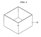
- a rectangular-box-shaped condenser microphone is easy to mount on a main board because it can easily recognize directionality of parts.
- the process of curling an edge portion of a case receiving parts is more difficult in the rectangular-box-shaped case than in the cylinder-shaped case.
- the present invention is directed to an electret condenser microphone that substantially obviates one or more problems due to limitations and disadvantages of the related art.
- An object of the present invention is to provide an SMD-type electret condenser microphone having a rectangular box shape, in which a curling process can be easily performed by chamfering an edge of a rectangular-box-shaped case, and sound leakage caused by the chamfer can be prevented by using a sealing pad.
- a rectangular-box-shaped electret condenser microphone including: a pair of a diaphragm and a backplate disposed to face each other, with a spacer being interposed therebetween; ⁇ conductive base for electrically conducting the diaphragm; an insulating base for electrically insulating the backplate and the conductive base; a polar ring for electrically conducting the diaphragm; a metal case having a rectangular box shape with one side open, such that the diaphragm, the backplate, the conductive base, the insulating base, and the polar ring are received, the metal case including a curling surface, an edge portion of which is chamfered; a printed circuit board on which circuit components are mounted, the printed circuit board including a conductive pattern and a protruding connection terminal; and a sealing pad mounted on the insulating base to seal a gap between
- the sealing pad may have a rectangular ring shape and may be formed of a flexible material, for example, rubber and resin.
- the curling surface of the case may be used as a connection terminal.
- the rectangular-box-shaped electret condenser microphone may further include a sound hole in a printed circuit board or a bottom surface of the case so as to receive an external sound.
- FIG. 1 is a perspective view of a case of a conventional rectangular-box-shaped condenser microphone
- FIG. 2 is a perspective view of a case of a rectangular-box-shaped condenser microphone according to an embodiment of the present invention
- FIG. 3 is a perspective view illustrating an assembled state of a rectangular-box-shaped condenser microphone according to an embodiment of the present invention
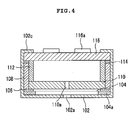
- FIG. 4 is a side sectional view of the rectangular-box-shaped condenser microphone illustrated in FIG. 3;
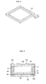
- FIG. 5 is a perspective view of a sealing pad according to an embodiment of the present invention.
- FIG. 6 is a side sectional view of a rectangular-box-shaped condenser microphone according to another embodiment of the present invention.
- FIG. 2 is a perspective view of a case of a rectangular-box-shaped condenser microphone according to an embodiment of the present invention
- FIG. 3 is a perspective view illustrating an assembled state of a rectangular-box-shaped condenser microphone according to an embodiment of the present invention
- FIG. 4 is a side sectional view of the rectangular-box-shaped condenser microphone illustrated in FIG. 3.
- the rectangular-box-shaped condenser microphone includes a metal case 102, a polar ring 104a, a diaphragm 104, a spacer 106, an insulating base 108, a backplate 110 with a sound hole 110a, a conductive base 112, a rectangular-ring-shaped sealing pad 114, and a printed circuit board (PCB) 116.
- the metal case 102 has a rectangular box shape with one side open, such that parts are received therein. In the rectangular-box-shaped metal case 102, edge portions of curling surfaces 102c are chamfered for the purpose of easy curling.
- the polar ring 104a and the diaphragm 104 are built in the metal case 102.
- the rectangular-ring-shaped sealing pad 114 is used for preventing sound leakage.
- a conductive pattern and a protruding connection terminal 116a are formed in the PCB 116.
- the metal case 102 has a rectangular box shape with one side open, and four edges 102b of the open side are chamfered. Therefore, during the curling process, the end portions 102 of the adjacent surfaces do not overlap each other.
- the sound hole 102a is formed in the bottom surface of the case.
- the sound hole 102a may be formed in the PCB 116, instead of the case 102, depending on a sound entry structure of the condenser microphone.
- the diaphragm 104 and the backplate 110 are disposed to face each other, with the insulating spacer 106 being interposed therebetween.
- the diaphragm 104 can be vibrated by external sound.
- the diaphragm 104 is electrically connected to the PCB 116 through the polar ring 104a and the metal case 102.
- the backplate 110 and the conductive base 112 are electrically isolated from the metal case 102 by the insulating base 108. Since such a structure has been well known to those skilled in the art, further description will be omitted.
- the rectangular-ring-shaped sealing pad 114 prevents sound of the condenser microphone from leaking out.
- the sealing pad 114 is formed of a flexible material, for example, rubber and resin.
- the sealing pad 114 is mounted into the metal case 102 and then the PCB 116 is put into the metal case 102. Thereafter, when the metal case 102 is curled, the sealing pad 114 is pressed to seal the gap between the metal case 102 and the PCB 116.
- the sealing pad 114 is pressed by the curling process, its height is reduced from t1 to t2.
- the condenser microphone assembled in the above-mentioned way can be easily curled because the edge portions 102c of the adjacent surfaces of the case 102 do not overlap one another.
- the protruding connection terminal 116a makes it easy to perform an SMD process.
- Two or more connection terminals may be formed in the PCB 116.
- the curling surface 102c of the case 102 may be used as a ground terminal.
- FIG. 6 is a side sectional view of a rectangular-box-shaped condenser microphone according to another embodiment of the present invention.
- the rectangular-box-shaped condenser microphone includes a metal case 102, a polar ring 104a, a diaphragm 104, a spacer 106, an insulating base 108, a backplate 110 with a sound hole 110a, a conductive base 112, a rectangular-ring-shaped sealing pad 114, and a PCB 116.
- the metal case 102 has a rectangular box shape with one side open, such that parts are received therein.
- edge portions 102b of curling surfaces 102c are chamfered for the purpose of easy curling.
- the polar ring 104a and the diaphragm 104 are built in the metal case 102.
- the rectangular-ring-shaped sealing pad 114 is used for preventing sound leakage.
- a conductive pattern, a protruding connection terminal 116a, and a sound hole 116b are formed in the PCB 116.
- the condenser microphone of FIG. 6 has the sound hole 116b in the PCB 116, while the condenser microphone of FIG. 4 has the sound hole 102a in the case 102. Further description about other elements will be omitted for avoiding the duplication.
- the electret condenser microphone according to the embodiments of the present invention can be easily curled by chamfering the edge portions of the rectangular-box-shaped case. Furthermore, sound characteristics of the electret condenser microphone can be improved by sealing the gap between the case and the PCB using the sealing pad.
Landscapes
- Physics & Mathematics (AREA)
- Engineering & Computer Science (AREA)
- Acoustics & Sound (AREA)
- Signal Processing (AREA)
- Electrostatic, Electromagnetic, Magneto- Strictive, And Variable-Resistance Transducers (AREA)
- Details Of Audible-Bandwidth Transducers (AREA)
Applications Claiming Priority (1)
| Application Number | Priority Date | Filing Date | Title |
|---|---|---|---|
| KR1020060085180A KR100797440B1 (ko) | 2006-09-05 | 2006-09-05 | 사각통 형상의 일렉트릿 콘덴서 마이크로폰 |
Publications (2)
| Publication Number | Publication Date |
|---|---|
| EP1898666A2 true EP1898666A2 (de) | 2008-03-12 |
| EP1898666A3 EP1898666A3 (de) | 2012-04-18 |
Family
ID=38786591
Family Applications (1)
| Application Number | Title | Priority Date | Filing Date |
|---|---|---|---|
| EP07291069A Withdrawn EP1898666A3 (de) | 2006-09-05 | 2007-09-05 | Elektretkondensatormikrofon |
Country Status (9)
| Country | Link |
|---|---|
| US (1) | US20080056523A1 (de) |
| EP (1) | EP1898666A3 (de) |
| JP (1) | JP4800276B2 (de) |
| KR (1) | KR100797440B1 (de) |
| CN (1) | CN101141833B (de) |
| MY (1) | MY141669A (de) |
| SG (1) | SG140534A1 (de) |
| TW (1) | TWI331880B (de) |
| WO (1) | WO2008029973A1 (de) |
Cited By (2)
| Publication number | Priority date | Publication date | Assignee | Title |
|---|---|---|---|---|
| EP2051539A1 (de) * | 2007-10-18 | 2009-04-22 | BSE Co., Ltd. | MEMS-Mikrofongehäuse |
| EP2056620A1 (de) * | 2007-11-02 | 2009-05-06 | BSE Co., Ltd. | MEMS-Mikrophongehäuse mit Schallloch in der Leiterplatte |
Families Citing this family (5)
| Publication number | Priority date | Publication date | Assignee | Title |
|---|---|---|---|---|
| KR20090039376A (ko) * | 2007-10-18 | 2009-04-22 | 주식회사 비에스이 | 기생용량을 줄인 콘덴서 마이크로폰 조립체 |
| KR101109102B1 (ko) * | 2010-01-18 | 2012-01-31 | 주식회사 비에스이 | 멤스 마이크로폰 패키지 |
| KR101241475B1 (ko) | 2011-11-24 | 2013-03-11 | 이오스 재팬, 인코포레이티드 | 조립이 간편한 콘덴서 마이크로폰 |
| CN105578370A (zh) * | 2016-03-15 | 2016-05-11 | 深圳捷力泰科技开发有限公司 | 一种驻极体传声器 |
| CN108156564A (zh) * | 2018-02-28 | 2018-06-12 | 深圳捷力泰科技开发有限公司 | 驻极体传声器 |
Family Cites Families (22)
| Publication number | Priority date | Publication date | Assignee | Title |
|---|---|---|---|---|
| US4380041A (en) * | 1978-09-25 | 1983-04-12 | Motorola Inc. | Capacitor pressure transducer with housing |
| JP2739543B2 (ja) * | 1993-07-23 | 1998-04-15 | 株式会社ピーエフユー | 電子装置の外装ケース |
| JP3192100B2 (ja) * | 1996-11-08 | 2001-07-23 | 株式会社オーディオテクニカ | マイクロホン |
| JP2000050393A (ja) * | 1998-05-25 | 2000-02-18 | Hosiden Corp | エレクトレットコンデンサマイクロホン |
| JP3425599B2 (ja) * | 1999-06-18 | 2003-07-14 | Smk株式会社 | コンデンサマイクロホン |
| JP2002374598A (ja) * | 2001-06-13 | 2002-12-26 | Hosiden Corp | コンデンサマイクロホン |
| JP4697763B2 (ja) * | 2001-07-31 | 2011-06-08 | パナソニック株式会社 | コンデンサマイクロホン |
| US7184563B2 (en) * | 2003-03-04 | 2007-02-27 | Knowles Electronics Llc. | Electret condenser microphone |
| JP4095927B2 (ja) * | 2003-05-15 | 2008-06-04 | 株式会社オーディオテクニカ | コンデンサマイクロホンユニット |
| KR200330089Y1 (ko) * | 2003-07-29 | 2003-10-11 | 주식회사 비에스이 | 통합 베이스 및 이를 이용한 일렉트릿 콘덴서마이크로폰 |
| US7136500B2 (en) * | 2003-08-05 | 2006-11-14 | Knowles Electronics, Llc. | Electret condenser microphone |
| KR100549188B1 (ko) * | 2003-08-14 | 2006-02-10 | 주식회사 비에스이 | 통합 베이스 및 이를 이용한 일렉트릿 콘덴서 마이크로폰 |
| JP4272017B2 (ja) * | 2003-09-04 | 2009-06-03 | スター精密株式会社 | エレクトレットコンデンサマイクロホンの製造方法 |
| KR100544277B1 (ko) * | 2003-10-20 | 2006-01-23 | 주식회사 비에스이 | 단차를 형성한 케이스 및 이를 이용한 일렉트릿 콘덴서마이크로폰 |
| KR100675026B1 (ko) * | 2003-11-05 | 2007-01-29 | 주식회사 비에스이 | 메인 pcb에 콘덴서 마이크로폰을 실장하는 방법 |
| KR100531716B1 (ko) * | 2003-12-04 | 2005-11-30 | 주식회사 비에스이 | Smd용 콘덴서 마이크로폰 |
| KR100544283B1 (ko) * | 2004-01-20 | 2006-01-24 | 주식회사 비에스이 | 표면실장을 위한 평행육면체형 콘덴서 마이크로폰 |
| KR100540711B1 (ko) * | 2004-01-29 | 2006-01-11 | 주식회사 비에스이 | 위상지연필터 및 이를 이용한 단일 지향성 콘덴서마이크로폰 |
| KR100544282B1 (ko) * | 2004-02-24 | 2006-01-23 | 주식회사 비에스이 | 평행육면체형 콘덴서 마이크로폰 |
| KR100544279B1 (ko) * | 2004-02-27 | 2006-01-23 | 주식회사 비에스이 | 평행육면체형 지향성 콘덴서 마이크로폰 |
| KR20060091399A (ko) * | 2005-02-14 | 2006-08-21 | 주식회사 비에스이 | 공기유동 슬릿을 포함하는 콘덴서마이크로폰 케이스 |
| JP4150407B2 (ja) * | 2005-06-20 | 2008-09-17 | ホシデン株式会社 | 電気音響変換器 |
-
2006
- 2006-09-05 KR KR1020060085180A patent/KR100797440B1/ko not_active Expired - Fee Related
- 2006-12-29 WO PCT/KR2006/005860 patent/WO2008029973A1/en not_active Ceased
- 2006-12-29 MY MYPI20081621A patent/MY141669A/en unknown
-
2007
- 2007-02-27 CN CN2007100787996A patent/CN101141833B/zh not_active Expired - Fee Related
- 2007-03-03 TW TW096107406A patent/TWI331880B/zh not_active IP Right Cessation
- 2007-08-02 SG SG200705651-8A patent/SG140534A1/en unknown
- 2007-09-03 JP JP2007228004A patent/JP4800276B2/ja not_active Expired - Fee Related
- 2007-09-04 US US11/899,057 patent/US20080056523A1/en not_active Abandoned
- 2007-09-05 EP EP07291069A patent/EP1898666A3/de not_active Withdrawn
Cited By (2)
| Publication number | Priority date | Publication date | Assignee | Title |
|---|---|---|---|---|
| EP2051539A1 (de) * | 2007-10-18 | 2009-04-22 | BSE Co., Ltd. | MEMS-Mikrofongehäuse |
| EP2056620A1 (de) * | 2007-11-02 | 2009-05-06 | BSE Co., Ltd. | MEMS-Mikrophongehäuse mit Schallloch in der Leiterplatte |
Also Published As
| Publication number | Publication date |
|---|---|
| WO2008029973A1 (en) | 2008-03-13 |
| TW200814831A (en) | 2008-03-16 |
| CN101141833B (zh) | 2012-05-30 |
| EP1898666A3 (de) | 2012-04-18 |
| JP4800276B2 (ja) | 2011-10-26 |
| CN101141833A (zh) | 2008-03-12 |
| KR100797440B1 (ko) | 2008-01-23 |
| JP2008067384A (ja) | 2008-03-21 |
| SG140534A1 (en) | 2008-03-28 |
| US20080056523A1 (en) | 2008-03-06 |
| TWI331880B (en) | 2010-10-11 |
| MY141669A (en) | 2010-05-31 |
Similar Documents
| Publication | Publication Date | Title |
|---|---|---|
| US7260230B2 (en) | High performance microphone and manufacturing method thereof | |
| KR100673849B1 (ko) | 메인보드에 실장되는 콘덴서 마이크로폰 및 이를 포함하는이동통신 단말기 | |
| EP1898666A2 (de) | Elektretkondensatormikrofon | |
| JP4150407B2 (ja) | 電気音響変換器 | |
| US20080063232A1 (en) | Silicon condenser microphone | |
| US9788093B2 (en) | Audio transducer electrical connectivity | |
| US8144898B2 (en) | High performance microphone and manufacturing method thereof | |
| KR101276353B1 (ko) | 다기능 마이크로폰 조립체 및 그 제조방법 | |
| US7327851B2 (en) | Parallelepiped condenser microphone | |
| US8023670B2 (en) | Stray capacitance reduced condenser microphone | |
| US6678383B2 (en) | Capacitor microphone | |
| US10939192B2 (en) | Electret condenser microphone and manufacturing method thereof | |
| US7344405B2 (en) | Electro-acoustic transducer with holder | |
| CN109348384A (zh) | 扬声器和电子设备 | |
| CN101189909B (zh) | 利用密封垫的smd电容传声器及其制造方法 | |
| KR100437681B1 (ko) | 지향성 마이크로폰 | |
| KR100797438B1 (ko) | 커링공정이 필요없는 마이크로폰 및 그 조립방법 | |
| CN209017308U (zh) | 扬声器和电子设备 | |
| EP1725071A2 (de) | Kondensatormikrofon mit Belüftungssystem | |
| KR100722685B1 (ko) | 탄성을 갖는 도전링을 이용한 콘덴서 마이크로폰 | |
| KR100722684B1 (ko) | Pcb와 도전링의 접촉면적을 줄여 잡음 특성이 개선된콘덴서 마이크로폰 | |
| JP3354478B2 (ja) | エレクトレットコンデンサマイクロホン | |
| KR20060091399A (ko) | 공기유동 슬릿을 포함하는 콘덴서마이크로폰 케이스 | |
| KR20050101421A (ko) | 마이크로폰의 조립 방법 및 이를 위한 콘덴서 마이크로폰 | |
| KR100740461B1 (ko) | 디지털 출력 콘덴서 마이크로폰의 조립 방법 및 이를 위한 마이크로폰 케이스 구조 |
Legal Events
| Date | Code | Title | Description |
|---|---|---|---|
| PUAI | Public reference made under article 153(3) epc to a published international application that has entered the european phase |
Free format text: ORIGINAL CODE: 0009012 |
|
| 17P | Request for examination filed |
Effective date: 20070921 |
|
| AK | Designated contracting states |
Kind code of ref document: A2 Designated state(s): AT BE BG CH CY CZ DE DK EE ES FI FR GB GR HU IE IS IT LI LT LU LV MC MT NL PL PT RO SE SI SK TR |
|
| AX | Request for extension of the european patent |
Extension state: AL BA HR MK YU |
|
| PUAL | Search report despatched |
Free format text: ORIGINAL CODE: 0009013 |
|
| AK | Designated contracting states |
Kind code of ref document: A3 Designated state(s): AT BE BG CH CY CZ DE DK EE ES FI FR GB GR HU IE IS IT LI LT LU LV MC MT NL PL PT RO SE SI SK TR |
|
| AX | Request for extension of the european patent |
Extension state: AL BA HR MK RS |
|
| RIC1 | Information provided on ipc code assigned before grant |
Ipc: H04R 19/01 20060101AFI20120314BHEP |
|
| AKX | Designation fees paid |
Designated state(s): AT BE BG CH CY CZ DE DK EE ES FI FR GB GR HU IE IS IT LI LT LU LV MC MT NL PL PT RO SE SI SK TR |
|
| 17Q | First examination report despatched |
Effective date: 20130221 |
|
| STAA | Information on the status of an ep patent application or granted ep patent |
Free format text: STATUS: THE APPLICATION IS DEEMED TO BE WITHDRAWN |
|
| 18D | Application deemed to be withdrawn |
Effective date: 20150623 |