EP1899072B1 - Broyeur - Google Patents
Broyeur Download PDFInfo
- Publication number
- EP1899072B1 EP1899072B1 EP06753721.7A EP06753721A EP1899072B1 EP 1899072 B1 EP1899072 B1 EP 1899072B1 EP 06753721 A EP06753721 A EP 06753721A EP 1899072 B1 EP1899072 B1 EP 1899072B1
- Authority
- EP
- European Patent Office
- Prior art keywords
- comminution
- screening device
- cylinder
- screening
- crushing
- Prior art date
- Legal status (The legal status is an assumption and is not a legal conclusion. Google has not performed a legal analysis and makes no representation as to the accuracy of the status listed.)
- Expired - Lifetime
Links
Images
Classifications
-
- B—PERFORMING OPERATIONS; TRANSPORTING
- B02—CRUSHING, PULVERISING, OR DISINTEGRATING; PREPARATORY TREATMENT OF GRAIN FOR MILLING
- B02C—CRUSHING, PULVERISING, OR DISINTEGRATING IN GENERAL; MILLING GRAIN
- B02C18/00—Disintegrating by knives or other cutting or tearing members which chop material into fragments
- B02C18/06—Disintegrating by knives or other cutting or tearing members which chop material into fragments with rotating knives
- B02C18/16—Details
- B02C18/22—Feed or discharge means
- B02C18/2216—Discharge means
-
- B—PERFORMING OPERATIONS; TRANSPORTING
- B02—CRUSHING, PULVERISING, OR DISINTEGRATING; PREPARATORY TREATMENT OF GRAIN FOR MILLING
- B02C—CRUSHING, PULVERISING, OR DISINTEGRATING IN GENERAL; MILLING GRAIN
- B02C18/00—Disintegrating by knives or other cutting or tearing members which chop material into fragments
- B02C18/06—Disintegrating by knives or other cutting or tearing members which chop material into fragments with rotating knives
- B02C18/14—Disintegrating by knives or other cutting or tearing members which chop material into fragments with rotating knives within horizontal containers
Definitions
- the invention relates to a comminution device for comminuting different materials.
- a crushing device is known from GB 2344060 known.
- Such comminution devices are known in various designs. They consist of at least one comminution roller rotatably mounted in a machine frame with at least one comminution tool arranged thereon and at least one counterblade cooperating with the comminution tool. Furthermore, the known comminution devices have at least one screening device for the comminuted product, the housing of which at least partially encloses the comminution cylinder. Enclosing the housing through the screening device is necessary so that the shredded material can be completely absorbed.
- the crushing roller usually has a plurality of crushing tools which cooperate with a corresponding number of counter cutters.
- the screening device comprises the entire length of the crushing roller in order to be able to completely absorb all comminuted material.
- the object of the invention is solved by the features of claim 1.
- the comminution device consists of at least one comminution roller rotatably mounted in a machine frame with at least one comminution tool arranged thereon and with at least one counterblade cooperating with the comminution tool and having at least one comminution device for the comminuted product whose housing at least partially encloses the comminution cylinder characterized in that the screening device is arranged to be movable relative to the machine frame and / or the crushing roller. Due to the movable arrangement of the screening device for the comminution roller, the screening device is caused to reciprocate in the direction of the axis of the comminution cylinder in the comminution process, thereby producing a cleaning effect.
- the screening device is not always located only under the same point of the crushing roller or counter-blade, so that the resulting shredded material can be better distributed.
- the relative movement at the same time causes a better removal of the comminuted material from the screening device, which has further positive effects.
- the relative movement is provided for the screening device parallel to the axis of the crushing roller.
- This relative movement is characterized by a relatively simple feasibility. Due to the design of these machines, this is structurally most effective to accomplish.
- the relative movement is effected either in the machine frame itself and is provided as a so-called pendulum motion or reciprocating motion with respect to the roller.
- the machine frame, including the screening device is designed to be relatively movable to the roller. It is structurally no problem to oscillate the rollers back and forth in the manner of a pendulum motion. Such an embodiment is also included in the proposal according to the invention.
- Another aspect of the invention is characterized in that the screening device has openings which serve to fractionate the comminuted material and which are arranged facing the collecting side.
- This design of the screening device according to the invention ensures, on the one hand, that only comminuted material passes according to a designated fractionation into the screening device for removal and, on the other hand, that just not sufficiently comminuted material still remains in the comminuting area between the roller and counterblade and is processed accordingly again.
- the combination of the screening device with the corresponding openings with the relative movement of the screening device with respect to the machine frame or the crushing roller, it is now possible to use appropriate sieves, which just because of the relative movement not clog so quickly and experience a constant self-cleaning process.
- the sieve device is in the form of a basket, that is to say it surrounds the comminuting cylinder like a basket, at least in a region comprising half or more than half of the comminuting cylinder at the outer diameter.
- This basket-like training has several advantages. It leads to the fact that certain areas of the crushing roller can be subjected to a visual inspection even without dismantling the basket. Also, certain service work, such as changing crushers, done without disassembly of the screening device.
- the screening device is arranged away from the comminution cylinder or onto the comminution cylinder.
- the screening device can now be pivoted away.
- This can be used extremely favorably for service work and for cleaning work, for example when a product change of the comminuted material, since the accessibility to the screening device is now significantly improved.
- the crushing roller for certain maintenance and cleaning work is also more accessible, so that the above work can be realized much faster and therefore more cost-effective.
- a change of the side of the screening device, which faces the collecting side is possible if, for example, a modified fractionation for the comminuted material is desired.
- it is of course beneficial if the screening device is pivoted away from the crushing roller, then the change of the screen of the screening device takes place and after completion of this work, the screening device is pivoted back into its working position.
- a development of the invention provides that the openings of the screening device are variable with respect to their opening way or opening size. It is of course also possible to arrange corresponding grids or sieves on the collecting side facing side of the screening device, which are then interchangeable for a size change or change the fractionation. Both variants are encompassed by the solution according to the invention. This also achieves a higher universality of the shredding device according to the invention.
- the device has two comminution rollers, which in particular have an opposite direction of rotation. It is then provided, of course, that both rollers of a screening device preferably also enclosed like a basket become. Since the rollers are arranged in opposite directions, it is now possible to arrange a two-sided counter-blade in the center of the machine, resulting in further advantages. These advantages arise both in terms of maintenance and with regard to the comminution effect. Since the screening devices are formed wegschwenkbar in the variant according to the invention with two rollers, a cheaper maintenance or replacement service is also possible here. Furthermore, it can be arranged by the central storage of the counter blade such that a very favorable setting possibility arises with respect to shear blade to knife. Optionally, the counter-blade can also be arranged on a corresponding height-adjustable fastening device. The above-described advantages of the invention are also achieved in the embodiment with two crushing rollers.
- the comminution device according to the invention has a counter-blade which has cutters on both sides, which in each case interact with the comminuting tools of the comminution roller facing the cutting edge.
- the counter knife By the variants of the invention described above, it is also possible to form the counter knife cheaper as height adjustable. Of course, this embodiment is also feasible in the variant with only one crushing roller.
- the invention is not limited to a solution consisting of two crushing rollers with a counter blade and two-sided cutting.
- each with a screening device for each crushing roller is, according to a further embodiment of the invention, varies.
- a drive for each crushing roller and screening device preferably for all crushing rollers and screening devices is provided. It is advantageous if the crushing roller has, for example, an electric drive.
- a hydraulic drive is provided for the screening device or for the screening devices.
- the length or the extent of the relative movement of the screening device can be changed and corresponds at least to the distance with which the comminuting tools are arranged on the comminuting cylinder. This ensures that, due to the relative movement of the screening device, all parts of the side of the screening device facing the roller always travel in such a way that they pass through all areas equally with respect to the elevations and depressions of the roller. This achieves an excellent cleaning and sieving effect. The risk of clogging is thus almost completely eliminated.
- embodiments of the invention are also included, in which the relative movement with respect to the distance of the comminution tools on the comminution roller are larger or smaller.
- the invention is also characterized in that the position of the comminuting rollers in the device is oriented substantially horizontally. This does not exclude that the crushing rollers are inclined at a certain angle, for example, improves the removal of the shredded material. Consequently, then the screening devices are arranged accordingly. They enclose the crushing roller based on the diameter at least half.
- the screening device comprises the crushing roller in the lower direction in the Aufstellraum.
- the cutting roller seen in section encloses by about 45% to 60%.
- the invention also relates to the screening device as such, which can be retrofitted, for example, to certain size reduction devices.
- the screening device refers to all variants, which were previously described for the crushing device.
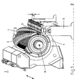
- the FIG. 1 shows a three-dimensional view of a first embodiment of the crushing device according to the invention.
- the reference numeral 1 denotes the crushing roller, which is rotatably mounted in a machine frame I.
- comminution tools 2 are arranged spirally.
- the comminution tools 2 are formed from a knife carrier, which is provided on the circumference of the crushing roller 1.
- the knife carriers themselves carry the comminution knives on their sides oriented in the cutting direction.
- the crushing tools 2 cooperate with a counter-blade 3, which are arranged on a portal or frame.
- the counter-blade 3 in this case has a multiplicity of cutting edges which are arranged corresponding to the comminuting tools and which interact with the comminuting blades of the comminution tools 2.
- the material to be crushed is transported by the crushing roller against the counter-blade and crushed there by the crushing tools in cooperation with the counter-blade.
- the comminuted material is collected by a screening device 4, which is arranged in a basket-like manner around the comminution cylinder 1.
- the screening device 4 comprises approximately 60% of the circumference of the comminution cylinder 1.
- the representation according to the FIG. 1 also shows that the screening device 4 is formed by the crushing roller 1 wegschwenkbar. Furthermore, in the FIG. 1 the distance a specified, which denotes the distance between the individual crushing tools 2 with each other on the crushing roller 1.
- the comminution cylinder 1 is set in a rotary motion. This rotational movement is provided in the illustrated variant in a clockwise direction, since the cutting edges are arranged accordingly on the crushing tools.
- This crushing tool act, as already described, together with the counter-blade 3, so that the material to be crushed is comminuted accordingly.
- the shredded good comes in the right size then into the screening device, when it passes through the openings provided there in the body of the screening device.
- the screening device is arranged analogously to the formation of the roller, wherein a slight inclination is advantageous, so that the material to be crushed can also be transported away at the same time low.
- the comminuted material then passes from the screening device, for example, to a corresponding conveyor, which removes the comminuted material.
- this is not essential to the invention and therefore not shown.
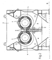
- FIG. 2 shows an embodiment of the solution according to the invention, in which two crushing rollers 1 are provided. Both crushing rollers 1 are each comprised of screening devices 4. In the center of the crushing device is the counter-blade 3, with a plurality of cutting edges, which cooperate with the crushing tools 2, which are indicated only schematically.
- the axes of the crushing rollers 1 are denoted by A and B.
- the installation level for the device is designated by reference II.
- the machine frame in turn bears the reference I.
- the frame is designated for the counter-blade, which may be formed, for example portal-like. In particular, this frame is designed to be height adjustable.
- the screening devices 4 are formed by the crushing rollers 1 each pivoting away to the left and right. This increases the ease of servicing and can, for example, have a very favorable effect on a change of the screens or else for necessary cleaning work in the case of comminution material changeover.
Landscapes
- Engineering & Computer Science (AREA)
- Food Science & Technology (AREA)
- Crushing And Pulverization Processes (AREA)
Claims (10)
- Déchiqueteuse consistant en au moins un rouleau de déchiquetage (1) maintenu de façon mobile dans un châssis de machine (I), un outil coupant (2) situé sur ce rouleau et interagissant avec une contre-lame (3), et un dispositif de crible (4), destiné à la matière déchiquetée, dont le cadre renferme au moins partiellement le rouleau de déchiquetage qui est mobile par rapport au châssis de machine (I) et/ou par rapport au rouleau de déchiquetage (1), caractérisée en ce que le mouvement relatif du dispositif de crible (4) est prévu parallèlement à l'axe (A, B) du rouleau de déchiquetage (1).
- Déchiqueteuse selon la revendication 1, caractérisée en ce que le dispositif de crible (4) comporte des ouvertures du côté d'où provient la matière servant à déstructurer la matière déchiquetée.
- Déchiqueteuse selon une des ou les deux revendications précédentes, caractérisée en ce que le dispositif de crible (4) est configuré comme un panier et/ou en ce que le dispositif de crible (4) peut pivoter afin de s'approcher ou de s'éloigner du rouleau de déchiquetage (1) et/ou en ce que les dimensions latérales ou diamétrales des ouvertures du dispositif de crible (4) peuvent être modifiées ou en ce que les ouvertures peuvent être changées.
- Déchiqueteuse selon une ou plusieurs des revendications précédentes, caractérisée en ce que la déchiqueteuse comporte deux rouleaux de déchiquetage (1) et en particulier deux rouleaux à mouvement opposé et/ou en ce que les contre-lames ont deux fils tranchants opposés permettant à chacun d'interagir avec les lames des outils coupants (2) des rouleaux de déchiquetage (1) à rotation opposée et/ou en ce que la hauteur de la contre-lame (3) est ajustable.
- Déchiqueteuse selon une ou plusieurs des revendications précédentes, caractérisée en ce qu'un dispositif de crible (4) est prévu pour chacun des rouleaux de déchiquetage (1) et/ou en ce qu'une commande est prévue pour chacune des rouleaux de déchiquetage (1) et dispositif de crible (4) et de préférence pour tous les rouleaux de déchiquetage (1) et de dispositifs de crible (4) et/ou en ce que le rouleau de déchiquetage (1) possède une commande électrique.
- Déchiqueteuse selon une ou plusieurs des revendications précédentes, caractérisée en ce que le dispositif de crible (4) possède une commande hydraulique et/ou en ce que la longueur ou la distance du mouvement relatif du dispositif de crible (4) est ajustable et correspond au moins à la distance (a) entre l'outil coupant (2) et le rouleau de déchiquetage (1).
- Déchiqueteuse selon une ou plusieurs des revendications précédentes, caractérisée en ce que les rouleaux de déchiquetage (1) sont placés à l'intérieur de la déchiqueteuse de façon approximativement horizontale.
- Déchiqueteuse selon une ou plusieurs des revendications précédentes, caractérisée en ce lorsque la déchiqueteuse est installée, le dispositif de crible (4) renferme la partie basse du rouleau de déchiquetage (1).
- Déchiqueteuse selon une ou plusieurs des revendications précédentes, caractérisée en ce que le dispositif de crible (4) renferme environ 45% à 60% de la section du rouleau de déchiquetage.
- Déchiqueteuse selon une ou plusieurs des revendications précédentes, caractérisée en ce que la ligne reliant les extrémités basse et haute du dispositif de crible (4) forme un angle allant de 40 à 60 degré par rapport au plan d'installation (II) de la déchiqueteuse.
Applications Claiming Priority (2)
| Application Number | Priority Date | Filing Date | Title |
|---|---|---|---|
| DE202005008077U DE202005008077U1 (de) | 2005-05-19 | 2005-05-19 | Zerkleinerungsvorrichtung |
| PCT/EP2006/004739 WO2006122814A1 (fr) | 2005-05-19 | 2006-05-18 | Broyeur |
Publications (2)
| Publication Number | Publication Date |
|---|---|
| EP1899072A1 EP1899072A1 (fr) | 2008-03-19 |
| EP1899072B1 true EP1899072B1 (fr) | 2013-07-10 |
Family
ID=36941929
Family Applications (1)
| Application Number | Title | Priority Date | Filing Date |
|---|---|---|---|
| EP06753721.7A Expired - Lifetime EP1899072B1 (fr) | 2005-05-19 | 2006-05-18 | Broyeur |
Country Status (5)
| Country | Link |
|---|---|
| US (1) | US7832667B2 (fr) |
| EP (1) | EP1899072B1 (fr) |
| CA (1) | CA2582776C (fr) |
| DE (1) | DE202005008077U1 (fr) |
| WO (1) | WO2006122814A1 (fr) |
Cited By (1)
| Publication number | Priority date | Publication date | Assignee | Title |
|---|---|---|---|---|
| CN110769937A (zh) * | 2017-06-28 | 2020-02-07 | 多普斯塔德特家族控股有限公司 | 粉碎设备 |
Families Citing this family (12)
| Publication number | Priority date | Publication date | Assignee | Title |
|---|---|---|---|---|
| DE202007017220U1 (de) * | 2007-12-09 | 2009-04-16 | Doppstadt Familienholding Gmbh | Vorrichtung zum Zerkleinern von festem Gut |
| DE102009012743A1 (de) * | 2008-11-26 | 2010-05-27 | Roland Dr. Nied | Feinmühle und Betriebsverfahren dafür |
| US8740121B1 (en) * | 2009-06-19 | 2014-06-03 | Republic Machine, Inc. | Rotary grinder/shredder |
| IT1396480B1 (it) * | 2009-10-23 | 2012-12-14 | C M G S P A | Perfezionamenti in macchine per triturare materiali vari come blocchi di plastica, residui di legno, cartonage e cosi' via. |
| CN102166576A (zh) * | 2010-12-24 | 2011-08-31 | 东莞市铁志电子有限公司 | 一种用于清洁纸加工设备的清洁用具 |
| DE102012211186A1 (de) * | 2012-06-28 | 2014-01-02 | Vecoplan Ag | Zerkleinerungsvorrichtung umfassend einen Zerkleinerungsrotor mit durchgehender Schneide |
| RU2517231C1 (ru) * | 2012-12-04 | 2014-05-27 | Федеральное государственное бюджетное образовательное учреждение высшего профессионального образования "Оренбургский государственный университет" | Дробилка |
| US20150115083A1 (en) * | 2013-10-31 | 2015-04-30 | Da Zhi Yun Enterprise Co. Ltd. | Recycling machine |
| US20170128950A1 (en) * | 2015-11-06 | 2017-05-11 | Innovaat.Com International Inc. | Low Power Biomass Shredder and Composting System Enabled for Continuous Feed of Material for Composting |
| CN108093894B (zh) * | 2018-02-01 | 2023-10-24 | 东北林业大学 | 一种剪切式秸秆超细粉碎装置 |
| US11484886B2 (en) | 2018-05-23 | 2022-11-01 | Vermeer Manufacturing Company | Shredder for comminuting bulk material |
| CN113424982B (zh) * | 2021-07-08 | 2023-03-07 | 云南昆船烟草设备有限公司 | 一种打叶器刀框距调节装置和刀框距可调的打叶器 |
Family Cites Families (9)
| Publication number | Priority date | Publication date | Assignee | Title |
|---|---|---|---|---|
| US5199666A (en) * | 1992-01-03 | 1993-04-06 | Williams Robert M | Rotary shredding apparatus with oscillating grate |
| FI95109C (fi) * | 1994-06-10 | 1995-12-27 | Pekka Lahti | Rumpuhakkurilaitteisto |
| DE29501067U1 (de) * | 1995-01-24 | 1996-05-23 | Weima Apparatebau GmbH, 74360 Ilsfeld | Zerkleinerungsmaschine |
| US5611495A (en) * | 1995-11-06 | 1997-03-18 | Williams; Robert M. | Rotary shredding apparatus with anti-jam means |
| DE19547828A1 (de) * | 1995-12-21 | 1997-06-26 | Krupp Foerdertechnik Gmbh | Verfahren und Vorrichtung zur Einstellung der maximalen Körnung von gebrochenem oder gemahlenem Stückgut |
| CN1099319C (zh) * | 1996-11-14 | 2003-01-22 | 俞信国 | 锤片粉碎机 |
| GB2344060B (en) * | 1998-11-28 | 2003-04-09 | Charles Lawrence Engineering L | Tyre granulator |
| CA2456442C (fr) * | 2001-08-21 | 2010-08-03 | Peterson Pacific Corporation | Systeme de tamis a demontage lateral pour dechiqueteur de materiaux |
| DE20301354U1 (de) * | 2003-01-29 | 2004-06-09 | Komptech Farwick Ges.M.B.H. | Zerkleinerungsvorrichtung |
-
2005
- 2005-05-19 DE DE202005008077U patent/DE202005008077U1/de not_active Expired - Lifetime
-
2006
- 2006-05-18 CA CA2582776A patent/CA2582776C/fr not_active Expired - Lifetime
- 2006-05-18 US US11/920,143 patent/US7832667B2/en not_active Expired - Fee Related
- 2006-05-18 EP EP06753721.7A patent/EP1899072B1/fr not_active Expired - Lifetime
- 2006-05-18 WO PCT/EP2006/004739 patent/WO2006122814A1/fr not_active Ceased
Cited By (1)
| Publication number | Priority date | Publication date | Assignee | Title |
|---|---|---|---|---|
| CN110769937A (zh) * | 2017-06-28 | 2020-02-07 | 多普斯塔德特家族控股有限公司 | 粉碎设备 |
Also Published As
| Publication number | Publication date |
|---|---|
| WO2006122814A1 (fr) | 2006-11-23 |
| CA2582776A1 (fr) | 2006-11-23 |
| DE202005008077U1 (de) | 2006-10-05 |
| CA2582776C (fr) | 2010-06-15 |
| US20090065619A1 (en) | 2009-03-12 |
| EP1899072A1 (fr) | 2008-03-19 |
| US7832667B2 (en) | 2010-11-16 |
Similar Documents
| Publication | Publication Date | Title |
|---|---|---|
| EP2012927B1 (fr) | Dispositif de desintegration | |
| DE69608918T3 (de) | Zerkleinerungsvorrichtung | |
| DE102006005017B3 (de) | Mehrwalzenbrecher | |
| EP2218507B1 (fr) | Dispositif de broyage de matériaux de chargement dotés d'éléments de démoulage | |
| EP3233288B1 (fr) | Dispositif de broyage avec un système à peigne | |
| DE202012007418U1 (de) | Zerkleinerungsvorrichtung | |
| EP1899072A1 (fr) | Broyeur | |
| EP2987556A1 (fr) | Broyeur | |
| EP2374544B1 (fr) | Dispositif de broyage de matériaux compostables | |
| EP0124138B1 (fr) | Méthode et dispositif pour le broyage de produits végétaux | |
| EP2563518B1 (fr) | Support de denture en chevron | |
| WO2015114156A1 (fr) | Dispositif de broyage | |
| EP1909976B1 (fr) | Dispositif de tamisage | |
| DE102009033584A1 (de) | Messer für eine Zerkleinerungsmaschine und Verwendung eines solchen in einer Zerkleinerungsmaschine | |
| DE102012006650A1 (de) | Zerkleinerungsvorrichtung | |
| DE19514951C2 (de) | Mobiler Abfall-Zerkleinerer | |
| DE4209278A1 (de) | Walzensegmentbrecher | |
| DE3614817A1 (de) | Vorrichtung zum brechen von grobstueckigem gut, insbesondere blockfoermigem sperrigem gut wie z.b. kohleelektroden | |
| EP1093861B1 (fr) | Agencement de tamis à étoiles ou disques comportant plusieurs arbres de tamisage | |
| EP0238827A1 (fr) | Dispositif de coupe pour faucheuse | |
| EP2987555A1 (fr) | Rotor | |
| CH426697A (de) | Maschine zum Abbauen von Feststoffen | |
| DE102011016658B4 (de) | Zerkleinerungsvorrichtung für kompostierbares Material | |
| DE3245373A1 (de) | Vorrichtung zum zerkleinern von abfallholz, insbesondere stubben, zu holzschnitzeln | |
| DE19718614C1 (de) | Zerkleinerungsmaschine für sperrige Gegenstände |
Legal Events
| Date | Code | Title | Description |
|---|---|---|---|
| PUAI | Public reference made under article 153(3) epc to a published international application that has entered the european phase |
Free format text: ORIGINAL CODE: 0009012 |
|
| 17P | Request for examination filed |
Effective date: 20070405 |
|
| AK | Designated contracting states |
Kind code of ref document: A1 Designated state(s): AT BE BG CH CY CZ DE DK EE ES FI FR GB GR HU IE IS IT LI LT LU LV MC NL PL PT RO SE SI SK TR |
|
| DAX | Request for extension of the european patent (deleted) | ||
| GRAP | Despatch of communication of intention to grant a patent |
Free format text: ORIGINAL CODE: EPIDOSNIGR1 |
|
| GRAS | Grant fee paid |
Free format text: ORIGINAL CODE: EPIDOSNIGR3 |
|
| GRAA | (expected) grant |
Free format text: ORIGINAL CODE: 0009210 |
|
| AK | Designated contracting states |
Kind code of ref document: B1 Designated state(s): AT BE BG CH CY CZ DE DK EE ES FI FR GB GR HU IE IS IT LI LT LU LV MC NL PL PT RO SE SI SK TR |
|
| REG | Reference to a national code |
Ref country code: GB Ref legal event code: FG4D Free format text: NOT ENGLISH |
|
| REG | Reference to a national code |
Ref country code: CH Ref legal event code: EP Ref country code: AT Ref legal event code: REF Ref document number: 620620 Country of ref document: AT Kind code of ref document: T Effective date: 20130715 |
|
| REG | Reference to a national code |
Ref country code: IE Ref legal event code: FG4D Free format text: LANGUAGE OF EP DOCUMENT: GERMAN |
|
| REG | Reference to a national code |
Ref country code: DE Ref legal event code: R096 Ref document number: 502006013003 Country of ref document: DE Effective date: 20130905 |
|
| PG25 | Lapsed in a contracting state [announced via postgrant information from national office to epo] |
Ref country code: SI Free format text: LAPSE BECAUSE OF FAILURE TO SUBMIT A TRANSLATION OF THE DESCRIPTION OR TO PAY THE FEE WITHIN THE PRESCRIBED TIME-LIMIT Effective date: 20130710 |
|
| REG | Reference to a national code |
Ref country code: NL Ref legal event code: VDEP Effective date: 20130710 |
|
| REG | Reference to a national code |
Ref country code: LT Ref legal event code: MG4D |
|
| PG25 | Lapsed in a contracting state [announced via postgrant information from national office to epo] |
Ref country code: CY Free format text: LAPSE BECAUSE OF FAILURE TO SUBMIT A TRANSLATION OF THE DESCRIPTION OR TO PAY THE FEE WITHIN THE PRESCRIBED TIME-LIMIT Effective date: 20130703 Ref country code: IS Free format text: LAPSE BECAUSE OF FAILURE TO SUBMIT A TRANSLATION OF THE DESCRIPTION OR TO PAY THE FEE WITHIN THE PRESCRIBED TIME-LIMIT Effective date: 20131110 Ref country code: SE Free format text: LAPSE BECAUSE OF FAILURE TO SUBMIT A TRANSLATION OF THE DESCRIPTION OR TO PAY THE FEE WITHIN THE PRESCRIBED TIME-LIMIT Effective date: 20130710 Ref country code: LT Free format text: LAPSE BECAUSE OF FAILURE TO SUBMIT A TRANSLATION OF THE DESCRIPTION OR TO PAY THE FEE WITHIN THE PRESCRIBED TIME-LIMIT Effective date: 20130710 Ref country code: PT Free format text: LAPSE BECAUSE OF FAILURE TO SUBMIT A TRANSLATION OF THE DESCRIPTION OR TO PAY THE FEE WITHIN THE PRESCRIBED TIME-LIMIT Effective date: 20131111 |
|
| PG25 | Lapsed in a contracting state [announced via postgrant information from national office to epo] |
Ref country code: NL Free format text: LAPSE BECAUSE OF FAILURE TO SUBMIT A TRANSLATION OF THE DESCRIPTION OR TO PAY THE FEE WITHIN THE PRESCRIBED TIME-LIMIT Effective date: 20130710 Ref country code: ES Free format text: LAPSE BECAUSE OF FAILURE TO SUBMIT A TRANSLATION OF THE DESCRIPTION OR TO PAY THE FEE WITHIN THE PRESCRIBED TIME-LIMIT Effective date: 20131021 Ref country code: GR Free format text: LAPSE BECAUSE OF FAILURE TO SUBMIT A TRANSLATION OF THE DESCRIPTION OR TO PAY THE FEE WITHIN THE PRESCRIBED TIME-LIMIT Effective date: 20131011 Ref country code: LV Free format text: LAPSE BECAUSE OF FAILURE TO SUBMIT A TRANSLATION OF THE DESCRIPTION OR TO PAY THE FEE WITHIN THE PRESCRIBED TIME-LIMIT Effective date: 20130710 Ref country code: PL Free format text: LAPSE BECAUSE OF FAILURE TO SUBMIT A TRANSLATION OF THE DESCRIPTION OR TO PAY THE FEE WITHIN THE PRESCRIBED TIME-LIMIT Effective date: 20130710 Ref country code: FI Free format text: LAPSE BECAUSE OF FAILURE TO SUBMIT A TRANSLATION OF THE DESCRIPTION OR TO PAY THE FEE WITHIN THE PRESCRIBED TIME-LIMIT Effective date: 20130710 |
|
| PG25 | Lapsed in a contracting state [announced via postgrant information from national office to epo] |
Ref country code: CY Free format text: LAPSE BECAUSE OF FAILURE TO SUBMIT A TRANSLATION OF THE DESCRIPTION OR TO PAY THE FEE WITHIN THE PRESCRIBED TIME-LIMIT Effective date: 20130710 |
|
| PG25 | Lapsed in a contracting state [announced via postgrant information from national office to epo] |
Ref country code: RO Free format text: LAPSE BECAUSE OF FAILURE TO SUBMIT A TRANSLATION OF THE DESCRIPTION OR TO PAY THE FEE WITHIN THE PRESCRIBED TIME-LIMIT Effective date: 20130710 Ref country code: DK Free format text: LAPSE BECAUSE OF FAILURE TO SUBMIT A TRANSLATION OF THE DESCRIPTION OR TO PAY THE FEE WITHIN THE PRESCRIBED TIME-LIMIT Effective date: 20130710 Ref country code: EE Free format text: LAPSE BECAUSE OF FAILURE TO SUBMIT A TRANSLATION OF THE DESCRIPTION OR TO PAY THE FEE WITHIN THE PRESCRIBED TIME-LIMIT Effective date: 20130710 Ref country code: CZ Free format text: LAPSE BECAUSE OF FAILURE TO SUBMIT A TRANSLATION OF THE DESCRIPTION OR TO PAY THE FEE WITHIN THE PRESCRIBED TIME-LIMIT Effective date: 20130710 Ref country code: SK Free format text: LAPSE BECAUSE OF FAILURE TO SUBMIT A TRANSLATION OF THE DESCRIPTION OR TO PAY THE FEE WITHIN THE PRESCRIBED TIME-LIMIT Effective date: 20130710 |
|
| PLBE | No opposition filed within time limit |
Free format text: ORIGINAL CODE: 0009261 |
|
| STAA | Information on the status of an ep patent application or granted ep patent |
Free format text: STATUS: NO OPPOSITION FILED WITHIN TIME LIMIT |
|
| PG25 | Lapsed in a contracting state [announced via postgrant information from national office to epo] |
Ref country code: IT Free format text: LAPSE BECAUSE OF FAILURE TO SUBMIT A TRANSLATION OF THE DESCRIPTION OR TO PAY THE FEE WITHIN THE PRESCRIBED TIME-LIMIT Effective date: 20130710 |
|
| 26N | No opposition filed |
Effective date: 20140411 |
|
| REG | Reference to a national code |
Ref country code: DE Ref legal event code: R097 Ref document number: 502006013003 Country of ref document: DE Effective date: 20140411 |
|
| PG25 | Lapsed in a contracting state [announced via postgrant information from national office to epo] |
Ref country code: LU Free format text: LAPSE BECAUSE OF FAILURE TO SUBMIT A TRANSLATION OF THE DESCRIPTION OR TO PAY THE FEE WITHIN THE PRESCRIBED TIME-LIMIT Effective date: 20140518 |
|
| REG | Reference to a national code |
Ref country code: CH Ref legal event code: PL |
|
| GBPC | Gb: european patent ceased through non-payment of renewal fee |
Effective date: 20140518 |
|
| PG25 | Lapsed in a contracting state [announced via postgrant information from national office to epo] |
Ref country code: CH Free format text: LAPSE BECAUSE OF NON-PAYMENT OF DUE FEES Effective date: 20140531 Ref country code: LI Free format text: LAPSE BECAUSE OF NON-PAYMENT OF DUE FEES Effective date: 20140531 Ref country code: MC Free format text: LAPSE BECAUSE OF FAILURE TO SUBMIT A TRANSLATION OF THE DESCRIPTION OR TO PAY THE FEE WITHIN THE PRESCRIBED TIME-LIMIT Effective date: 20130710 |
|
| REG | Reference to a national code |
Ref country code: IE Ref legal event code: MM4A |
|
| REG | Reference to a national code |
Ref country code: FR Ref legal event code: ST Effective date: 20150130 |
|
| PG25 | Lapsed in a contracting state [announced via postgrant information from national office to epo] |
Ref country code: IE Free format text: LAPSE BECAUSE OF NON-PAYMENT OF DUE FEES Effective date: 20140518 |
|
| PG25 | Lapsed in a contracting state [announced via postgrant information from national office to epo] |
Ref country code: GB Free format text: LAPSE BECAUSE OF NON-PAYMENT OF DUE FEES Effective date: 20140518 Ref country code: FR Free format text: LAPSE BECAUSE OF NON-PAYMENT OF DUE FEES Effective date: 20140602 |
|
| REG | Reference to a national code |
Ref country code: AT Ref legal event code: MM01 Ref document number: 620620 Country of ref document: AT Kind code of ref document: T Effective date: 20140518 |
|
| PG25 | Lapsed in a contracting state [announced via postgrant information from national office to epo] |
Ref country code: AT Free format text: LAPSE BECAUSE OF NON-PAYMENT OF DUE FEES Effective date: 20140518 |
|
| PG25 | Lapsed in a contracting state [announced via postgrant information from national office to epo] |
Ref country code: BG Free format text: LAPSE BECAUSE OF FAILURE TO SUBMIT A TRANSLATION OF THE DESCRIPTION OR TO PAY THE FEE WITHIN THE PRESCRIBED TIME-LIMIT Effective date: 20130710 |
|
| PG25 | Lapsed in a contracting state [announced via postgrant information from national office to epo] |
Ref country code: BE Free format text: LAPSE BECAUSE OF FAILURE TO SUBMIT A TRANSLATION OF THE DESCRIPTION OR TO PAY THE FEE WITHIN THE PRESCRIBED TIME-LIMIT Effective date: 20140531 Ref country code: TR Free format text: LAPSE BECAUSE OF FAILURE TO SUBMIT A TRANSLATION OF THE DESCRIPTION OR TO PAY THE FEE WITHIN THE PRESCRIBED TIME-LIMIT Effective date: 20130710 Ref country code: HU Free format text: LAPSE BECAUSE OF FAILURE TO SUBMIT A TRANSLATION OF THE DESCRIPTION OR TO PAY THE FEE WITHIN THE PRESCRIBED TIME-LIMIT; INVALID AB INITIO Effective date: 20060518 |
|
| REG | Reference to a national code |
Ref country code: DE Ref legal event code: R082 Ref document number: 502006013003 Country of ref document: DE Representative=s name: VON ROHR PATENTANWAELTE PARTNERSCHAFT MBB, DE |
|
| REG | Reference to a national code |
Ref country code: DE Ref legal event code: R081 Ref document number: 502006013003 Country of ref document: DE Owner name: DOPPSTADT BETEILIGUNGS GMBH, DE Free format text: FORMER OWNER: DOPPSTADT CALBE GMBH, 39240 CALBE, DE Ref country code: DE Ref legal event code: R082 Ref document number: 502006013003 Country of ref document: DE Representative=s name: VON ROHR PATENTANWAELTE PARTNERSCHAFT MBB, DE Ref country code: DE Ref legal event code: R081 Ref document number: 502006013003 Country of ref document: DE Owner name: DOPPSTADT FAMILIENHOLDING GMBH, DE Free format text: FORMER OWNER: DOPPSTADT CALBE GMBH, 39240 CALBE, DE Ref country code: DE Ref legal event code: R081 Ref document number: 502006013003 Country of ref document: DE Owner name: LIG GMBH, DE Free format text: FORMER OWNER: DOPPSTADT CALBE GMBH, 39240 CALBE, DE |
|
| REG | Reference to a national code |
Ref country code: DE Ref legal event code: R081 Ref document number: 502006013003 Country of ref document: DE Owner name: DOPPSTADT BETEILIGUNGS GMBH, DE Free format text: FORMER OWNER: DOPPSTADT FAMILIENHOLDING GMBH, 42555 VELBERT, DE Ref country code: DE Ref legal event code: R082 Ref document number: 502006013003 Country of ref document: DE Representative=s name: VON ROHR PATENTANWAELTE PARTNERSCHAFT MBB, DE Ref country code: DE Ref legal event code: R081 Ref document number: 502006013003 Country of ref document: DE Owner name: LIG GMBH, DE Free format text: FORMER OWNER: DOPPSTADT FAMILIENHOLDING GMBH, 42555 VELBERT, DE |
|
| REG | Reference to a national code |
Ref country code: DE Ref legal event code: R081 Ref document number: 502006013003 Country of ref document: DE Owner name: DOPPSTADT BETEILIGUNGS GMBH, DE Free format text: FORMER OWNER: LIG GMBH, 42555 VELBERT, DE Ref country code: DE Ref legal event code: R082 Ref document number: 502006013003 Country of ref document: DE Representative=s name: VON ROHR PATENTANWAELTE PARTNERSCHAFT MBB, DE Ref country code: DE Ref legal event code: R081 Ref document number: 502006013003 Country of ref document: DE Owner name: LIG GMBH, DE Free format text: FORMER OWNER: LIG GMBH, 42555 VELBERT, DE |
|
| REG | Reference to a national code |
Ref country code: DE Ref legal event code: R081 Ref document number: 502006013003 Country of ref document: DE Owner name: DOPPSTADT BETEILIGUNGS GMBH, DE Free format text: FORMER OWNER: LIG GMBH, 42551 VELBERT, DE |
|
| P01 | Opt-out of the competence of the unified patent court (upc) registered |
Effective date: 20230613 |
|
| PGFP | Annual fee paid to national office [announced via postgrant information from national office to epo] |
Ref country code: DE Payment date: 20240521 Year of fee payment: 19 |
|
| REG | Reference to a national code |
Ref country code: DE Ref legal event code: R119 Ref document number: 502006013003 Country of ref document: DE |
|
| PG25 | Lapsed in a contracting state [announced via postgrant information from national office to epo] |
Ref country code: DE Free format text: LAPSE BECAUSE OF NON-PAYMENT OF DUE FEES Effective date: 20251202 |