EP1900135B1 - Adaptive modulation für kooperative kodierte systeme - Google Patents
Adaptive modulation für kooperative kodierte systeme Download PDFInfo
- Publication number
- EP1900135B1 EP1900135B1 EP06780006A EP06780006A EP1900135B1 EP 1900135 B1 EP1900135 B1 EP 1900135B1 EP 06780006 A EP06780006 A EP 06780006A EP 06780006 A EP06780006 A EP 06780006A EP 1900135 B1 EP1900135 B1 EP 1900135B1
- Authority
- EP
- European Patent Office
- Prior art keywords
- source
- partner
- modulation mode
- throughput
- largest
- Prior art date
- Legal status (The legal status is an assumption and is not a legal conclusion. Google has not performed a legal analysis and makes no representation as to the accuracy of the status listed.)
- Not-in-force
Links
Images


Classifications
-
- H—ELECTRICITY
- H04—ELECTRIC COMMUNICATION TECHNIQUE
- H04B—TRANSMISSION
- H04B7/00—Radio transmission systems, i.e. using radiation field
- H04B7/14—Relay systems
- H04B7/15—Active relay systems
- H04B7/155—Ground-based stations
- H04B7/15592—Adapting at the relay station communication parameters for supporting cooperative relaying, i.e. transmission of the same data via direct - and relayed path
-
- H—ELECTRICITY
- H04—ELECTRIC COMMUNICATION TECHNIQUE
- H04L—TRANSMISSION OF DIGITAL INFORMATION, e.g. TELEGRAPHIC COMMUNICATION
- H04L1/00—Arrangements for detecting or preventing errors in the information received
- H04L1/0001—Systems modifying transmission characteristics according to link quality, e.g. power backoff
- H04L1/0002—Systems modifying transmission characteristics according to link quality, e.g. power backoff by adapting the transmission rate
- H04L1/0003—Systems modifying transmission characteristics according to link quality, e.g. power backoff by adapting the transmission rate by switching between different modulation schemes
-
- H—ELECTRICITY
- H04—ELECTRIC COMMUNICATION TECHNIQUE
- H04L—TRANSMISSION OF DIGITAL INFORMATION, e.g. TELEGRAPHIC COMMUNICATION
- H04L27/00—Modulated-carrier systems
- H04L27/0008—Modulated-carrier systems arrangements for allowing a transmitter or receiver to use more than one type of modulation
-
- H—ELECTRICITY
- H04—ELECTRIC COMMUNICATION TECHNIQUE
- H04L—TRANSMISSION OF DIGITAL INFORMATION, e.g. TELEGRAPHIC COMMUNICATION
- H04L27/00—Modulated-carrier systems
- H04L27/32—Carrier systems characterised by combinations of two or more of the types covered by groups H04L27/02, H04L27/10, H04L27/18 or H04L27/26
- H04L27/34—Amplitude- and phase-modulated carrier systems, e.g. quadrature-amplitude modulated carrier systems
- H04L27/3494—Amplitude- and phase-modulated carrier systems, e.g. quadrature-amplitude modulated carrier systems using non - square modulating pulses, e.g. using raised cosine pulses; Partial response QAM, i.e. with partial response pulse shaping
-
- H—ELECTRICITY
- H04—ELECTRIC COMMUNICATION TECHNIQUE
- H04L—TRANSMISSION OF DIGITAL INFORMATION, e.g. TELEGRAPHIC COMMUNICATION
- H04L1/00—Arrangements for detecting or preventing errors in the information received
- H04L1/12—Arrangements for detecting or preventing errors in the information received by using return channel
- H04L1/16—Arrangements for detecting or preventing errors in the information received by using return channel in which the return channel carries supervisory signals, e.g. repetition request signals
- H04L1/18—Automatic repetition systems, e.g. Van Duuren systems
-
- H—ELECTRICITY
- H04—ELECTRIC COMMUNICATION TECHNIQUE
- H04L—TRANSMISSION OF DIGITAL INFORMATION, e.g. TELEGRAPHIC COMMUNICATION
- H04L1/00—Arrangements for detecting or preventing errors in the information received
- H04L2001/0092—Error control systems characterised by the topology of the transmission link
- H04L2001/0097—Relays
-
- H—ELECTRICITY
- H04—ELECTRIC COMMUNICATION TECHNIQUE
- H04L—TRANSMISSION OF DIGITAL INFORMATION, e.g. TELEGRAPHIC COMMUNICATION
- H04L25/00—Baseband systems
- H04L25/02—Details ; arrangements for supplying electrical power along data transmission lines
- H04L25/03—Shaping networks in transmitter or receiver, e.g. adaptive shaping networks
- H04L25/03006—Arrangements for removing intersymbol interference
- H04L2025/0335—Arrangements for removing intersymbol interference characterised by the type of transmission
- H04L2025/03375—Passband transmission
- H04L2025/0342—QAM
-
- Y—GENERAL TAGGING OF NEW TECHNOLOGICAL DEVELOPMENTS; GENERAL TAGGING OF CROSS-SECTIONAL TECHNOLOGIES SPANNING OVER SEVERAL SECTIONS OF THE IPC; TECHNICAL SUBJECTS COVERED BY FORMER USPC CROSS-REFERENCE ART COLLECTIONS [XRACs] AND DIGESTS
- Y02—TECHNOLOGIES OR APPLICATIONS FOR MITIGATION OR ADAPTATION AGAINST CLIMATE CHANGE
- Y02D—CLIMATE CHANGE MITIGATION TECHNOLOGIES IN INFORMATION AND COMMUNICATION TECHNOLOGIES [ICT], I.E. INFORMATION AND COMMUNICATION TECHNOLOGIES AIMING AT THE REDUCTION OF THEIR OWN ENERGY USE
- Y02D30/00—Reducing energy consumption in communication networks
- Y02D30/50—Reducing energy consumption in communication networks in wire-line communication networks, e.g. low power modes or reduced link rate
Definitions
- the present invention relates to a system and method for a coded cooperative wireless communication system in which users can adapt their modulation mode based on their channel qualities to maximize data throughput.
- Cooperative wireless communication enables nodes to use each other's antenna to obtain an effective form of spatial diversity.
- a partnering node processes signals overheard from an original source and then transmit them to a destination, such as an AP.
- the destination e.g., AP, combines signals received from the original node and the partner, thus creating an efficient form of spatial diversity.
- nodes are able to transmit their data at multiple rates and are allowed to adapt their data rates to match their channel conditions such that the throughput for their given channel conditions is maximized, see, respectively, IEEE 802.11, "Wireless LAN MAC and PHY Specifications, Standard, Aug. 1999 and G. Holland, et al. "A Rate-Adaptive MAC Protocol for Multi-Hop Wireless Networks," Proc of the 7th Annual International Conference on Mobile Computing and Networking, pp 236-251, Rome, Italy, 2001 .
- Adaptation of modulation is also described in ZINA LIN ET AL, "Adaptive Modulation for coded cooperative systems” SINAL PROCESSING ADVANCES IN WIRELESS COMMUNICATIONS, 2005 IEEE 6TH WORKSHOP ON NEW YORK, NY, US JUNE 2-8, 2005, PISCATAWAY, NJ, USA, IEEE, 2 June 2005 (2005-06-02), pages 615-619, ISBN: 0-7803-8867-4 .
- the present invention provides an apparatus and method for cooperating partners of coded cooperative systems to select their modulation modes based on their channel qualities to an access point (AP) in order to optimize the data throughput of the original user to the AP.
- AP access point
- the source's channel quality is taken into consideration in the selection of the partner's modulation rate. Further, in the present invention the source also takes into consideration its partner's channel quality as well when selecting the source's modulation rate.
- the present invention defmes a system and method according to the appended claims for cooperating partners of a coded cooperative system to determine
- ⁇ 1 and ⁇ 2 denote the average received SNR at the destination 203 from S1 201 and S2 202, respectively.
- the channel between partnering users S1 201 and S2 202 is symmetric.
- the average received SNR for the inter-user channel by ⁇ in.
- cooperation is via time division multiplexing as illustrated in FIG. 2B and assume an underlying convolutional code.
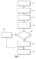
- each user divides its own slot in two, as illustrated at step 101 in the flow chart of FIG. 1 .
- the source transmits half of its coded bits, as indicated at step 103 of FIG.1 . This transmission is received by both the partner and the destination at step 104.
- the partner attempts to decode the information bits of the source at step 105.
- An error detection mechanism such as cyclic Redundancy Check (CRC) indicates whether the decoded copy at the partner is identical to the original.
- CRC cyclic Redundancy Check
- the partner re-encodes the information bits using different parity bits and transmits them in the second N/2 channel uses 232, as indicated at step 107. If decoding is not successful, the source continues the transmission by itself at step 106. The destination combines signals received in all N channel uses and decodes the combined signal. In the next frame, the roles 233 234 of the source and partner are reversed. Since multi-hop mitigates the path loss effect, multi-hop embodiments are provided in the system and method of the present invention. It is assumed that the transmitted energy per symbol is fixed as ⁇ and that S 1 is the source node and S 2 acts as a pure relay. The packet is first transmitted from S 1 to S 2 . Upon successful reception, the relay S 2 forwards the packet to the destination.
- both partnering nodes can select their own modulation modes from candidates based on the averaged received SNRs in the destination, e.g., AP.
- the candidates include, but are not limited to, binary phase shift keying (BPSK), quadrature phase shift keying (QPSK), and 16 state quadrature amplitude modulation (16-QAM).
- BPSK binary phase shift keying
- QPSK quadrature phase shift keying
- 16-QAM 16 state quadrature amplitude modulation
- K 1 and K 2 denote the number of bits per symbol sent by S 1 and S 2 respectively in multi-hop.
- M 1 M 2 .
- N 1 N 2 .
- Multi-hop S 1 re -transmits the coded packet to S 2 until the packet is successfully received by S 2 . Then S 2 relays the packet to the destination. If there is an error in the received packet at the destination, S 2 re-transmits.
- P QS m,in and P QS m,2 denote the FER of the channel code for the quasi-static channel from S 1 -to- S 2 and from S 2 -to-destination in multi-hop respectively.
- the multi-hop scheme it takes an average 1 1 - P m , in QS transmissions in the first hop (from S 1 to S 2 ) and 1 1 - P m , 2 QS transmissions in the second hop (from S 2 to the destination) to get one packet through.
- the first hop transmission takes B 1 - P m , in QS ⁇ K 1 ⁇ R s ⁇ R seconds and the second hop takes B 1 - P m , 2 QS ⁇ K 2 ⁇ R s ⁇ R seconds.
- P m in QS and P m , 2 QS depend on the channel quality from S 1 to S 2 and from S 2 to the destination independently
- S 1 and S 2 adapt their modulation rates K 1 and K 2 based on channel qualities of S 1 -to- S 2 and S 2 -to-destination independently.
- S i transmits half of the coded bits to the destination and S j, , where i ⁇ j,i,j ⁇ ⁇ 1,2 ⁇ . If S i decodes information bits sent by S j correctly, S j sends the other half of the coded bits to the destination. If there is an error at the destination, all successive packets are transmitted cooperatively by S i and S j . If, on the other hand, S j cannot decode S i 's information, S i continues transmitting the remaining coded bits. In this case, all retransmissions will come directly from the source.
- P f , i QS denote the FER for the quasi-static S i -to-destination channel
- P f , i in denote the FER of the first half channel code for the quasi-static channel of S i-to- S j
- P f , i BF denote the FER for the cooperative block fading channel when destination receives half of the packet from S i and the remaining half from S j .
- P f , i QS is not necessarily equal to P ⁇ f , i QS as S i may have a different modulation scheme for non-cooperative (direct) transmission and cooperative scheme.
- S 1 transmits all the coded bits to S 2 with transmit energy ⁇ /2 per symbol, but in coded cooperation, S 1 sends only half of the coded bits to S 2 with transmit energy ⁇ per symbol.
- P m , in QS is different from P f , 1 in . It can be observed from Eqn.
- Proposition 1 For fixed ⁇ 1 and ⁇ in P f , 1 in and selected N 1 , M 1 and M 2 , G ⁇ ,1 increases with ⁇ 2 .
- Proposition 1 shows that when a partner is in a better situation, the throughput gain increases. In other words, cooperating with a "better" partner brings more benefits to the original user, where better means a better quality channel to the destination.
- Proposition 2 When users S 1 201 and S 2 202 use a modulation rate with M 1 bits/symbol and M 2 bits/symbol, respectively, during cooperation, user 1 obtains a throughput gain from cooperation, i.e., G ⁇ ,1 > 1 if and only if ⁇ M 1 ⁇ 1 - P f , 1 BF 1 - P f , 1 QS where ⁇ M 1 ⁇ 2 M 1 M 2 + 1
- the partner keeps the same modulation mode as the one when it communicates with the destination individually but the source changes its modulation mode dynamically. Since the source may use different modulation modes from the one in its individual communication with the destination, M 1 is not necessarily same as N 1 then P f , 1 no - coop is not always equal to P f , 1 qs .
- M 1 is not necessarily same as N 1 then P f , 1 no - coop is not always equal to P f , 1 qs .
- the throughput gain of the source due to cooperation is dependent on the FER of the inter-user channel, which is different from the case that the source fixes its own modulation mode. Therefore, whether the cooperation improves the source's throughput or not depends on the inter-user channel quality if the source adapts its modulation rate during cooperation.
- the following is an analysis of the case where the source fixes its modulation mode and the partner changes its modulation mode that investigates the optimal modulation modes that can be used by the partner in different ranges of SNRs such that the data throughput for the source is maximized.
- M 1 ⁇ M 2 is considered first.
- the following sections investigate (a) the partner selects its modulation mode based only on its own channel quality, (b) the original user's channel quality also affects the partner's modulation rate choice and (c) the partner selects the best modulation rate depending on different ranges of SNRs. Finally, an analysis is presented of combining these three cases with the case of M 1 > M 2 to determine the best modulation rate pair for the partnering users at the different ranges of SNR pairs for these two users such that the choice maximizes the throughput gain for the source.
- M 1 ⁇ M 2 we have six possible values of ⁇ M 1 .
- result 4 can be applied, that is if P f , 1 BF , 3 > ⁇ 23 , G ⁇ 2 is the largest and the throughput is maximized if the partner uses QPSK modulation mode; otherwise, G ⁇ 3 is the largest and 16-QAM modulation mode selected by the partner brings the largest throughput to the original user.
- the source has a higher modulation rate than the partner, the values of ⁇ M 1 n change. But, the above algorithm is used to determine the conditions under which the selected modulation rate used by the partner is the best, with the goal source's data throughput.
- the first case is when the partner fixes its modulation rate and how the source adapts its modulation mode
- the second case is both partnering users adapt their modulation modes simultaneously.
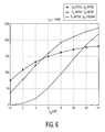
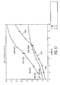
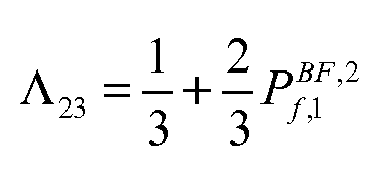
- FIG. 12 shows the values of P f , 1 BF for the cases that S 1 uses BPSK and S 1 uses QPSK and 16-QAM, respectively, and the threshold values of ⁇ 12, ⁇ 13 , and ⁇ 23 .
- P f , 1 BF , 2 is larger than ⁇ 12
- P BF ,3 is larger than ⁇ 23 .
- S 2 selects 16-QAM to maximize the throughput for S 1 . All these thresholds of ⁇ 2 match the results shown in FIG. 7 .
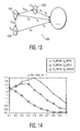
- the following sections address the choice of partner by a source, i.e., how to choose a best partner among a list of candidates such that the data throughput of the source can be improved most by cooperating with the partner. Also presented in the following sections is an illustration of how the source's channel quality affects the partner choice. Without loss of generality, consider a scenario where the possible partners are classified into two groups, one group has very good channel quality to the destination, but low inter-user SNR, the other group has a very good inter-user channel quality, but the channel to the destination does not have good quality. Such a scenario is depicted in FIG. 13 .
- S 2 represents the partner with good quality inter-user channel (e.g. S 2 could be close to SI) and similar channel quality to the destination as the source
- S 1 , and S 3 represent the partner with good channel to the destination (e.g. S 3 is close to the destination).
- cooperation with S 2 results in two level diversity and cooperation with S 3 always helps the source improve the throughput significantly, as illustrated in the foregoing numerical examples. Therefore, it is of interest to find which effect dominates and whether the source's channel quality affects its partner's selection of modulation rate.
- the following numerical example illustrates the partner choice problem.
- Path loss effect is incorporated with flat Rayleigh fading in the following example.
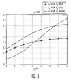
- D 1 fixed at 1.0 and the angle between S 1 and S 2 as ⁇ 6 and ⁇ N 0 is assumed to be 0dB and i 5dB, respectively we obtain the throughput gains for the different distances between the partner and the destination.
- the distance between the partner and the destination is smaller, which means the partner is close to the destination but further away from the source, the inter-user channel between the two partnering users is worse and hence, P f in is higher.
- 16QAM is the best modulation rate for use by S 3 to achieve the maximum throughput gain for S 1 when S 1 cooperates with S 3 .
- QPSK is the best modulation rate used by S 2 such that the throughput gain for S 1 due to cooperation between S 1 and S 2 is maximized.
- S 1 chooses S 3 rather than S 2 to achieve greater cooperation gain as the better user can help S 1 more when S 1 is not experiencing poor channel quality to the source.
- the source chooses the partner that can help the source achieve a lower FER value rather than the partner that has a higher data rate. From these two examples it follows that when there is a list of candidates that use different modulation modes to maximize the throughput gain for the source, the source's channel quality affecting its best partner selection such that its throughput gain can be improved most.
- the system and method of the present invention provide adaptive modulation for at cooperating users in coded cooperative systems to optimize the throughput for a source.
- the throughput gain due to cooperation has been defined in terms of the conditions under which cooperation improves the data throughput of the source.
- Channel qualities have been demonstrated to affect the throughput gain due to cooperation.
- a method has been provided for selecting a partner's modulation rate based on two operating users' channel qualities conditions 1- 4.
- Cooperation improves the data throughput for the source and when the adaptive modulation of the present invention is used by the cooperating users, throughput can be further increased.
- the present invention also provides a way for a source to select a partner among a plurality of available partners, by having the selected partner relaying information for the source such that the throughput gain of the source due to cooperation with the selected partner is the highest achievable of that which could be achieved by partnering with each of the available partners.
- FIG. 16 illustrates how the throughput of direct transmission changes as a function of SNR and modulation mode.
- SNR SNR
- modulation mode As illustrated in FIG. 16 , among BPSK, QPSK and 16QAM, when the received SNR is below 0 dB, direct transmission with BPSK modulation has the highest throughput. When the received SNR is 0dB-6dB, QPSK is the preferred modulation preferred. Finally, when the received SNR is highter than 6 dB, 16QAM modulation is the best choice.
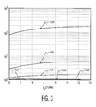
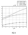
- FIG.17 illustrates the normalized throughput (with respect to R s ) of direct transmission, multihop and cooperative scheme.
- FIG. 4 shows that coded cooperation with adaptive modulation leads to much higher throughput than either multi -hop transmission with adaptive modulation or direct transmission with adaptive modulation.
- the comparison of the throughput value of cooperation with that of direct transmission for this example leads to the result that cooperation provides at least a 20% gain of cooperation over direct transmission.
- SNR is below 4 dB, the gain is as much as 100%.
- the sources of gain include diversity at the receiver, cooperative channel coding and multi -hop.
- the gain solely due to multi-hop is also illustrated in FIG. 17 . While multi-hop transmission with adaptive modulation is inferior to cooperation it provides superior throughput over direct transmission with adaptive modulation for low to medium SNR. But, when SNR is sufficiently high (about 6 dB in this example), the throughput of direct transmission is higher than that of multi-hop transmission. There are two main reasons for this behavior. First, the highest modulation mode is 16 QAM, and, therefore, even when the received SNR in every hop is high enough, no higher order modulation can be used. Second, when SNR increases, the FER of direct transmission also decreases, resulting in a smaller difference in FER between direct transmission and each multiphop transmission. In other words, the path loss does not have a significant effect in FER performance when SNR is high enough. As a result, multi-hop transmission does not have any advantage over direct transmission in terms of throughput for high SNR.
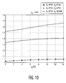
- the optimum modulation rate per hop is determined by the channel qualities of each hop, i.e., S 1 -to- S 2 and S 2 -to-destination separately.
- S 1 -to- S 2 the channel qualities of each hop
- S 2 the optimum modulation rate per hop is determined by the channel qualities of each hop, i.e., S 1 -to- S 2 and S 2 -to-destination separately.
- S 1 and S 2 both select QPSK to maximize throughput.
- SNR increases, i.e., for ⁇ N 0 > 0 dB , 16 QAM becomes the best modulation choice.
- FIG. 19 illustrates an apparatus 1900 for selecting a partner and adapting modes of the source and the partner comprising an antenna 1901 connected to a transmitter 1902 and a receiver 1903 for a source to send and receive messages, respectively, to and from candidate partners / relays.
- the messages received by the receiver 1903 are processed by a partner selection and modulation mode adaptation module 1904 which determines the quality of the channels and the improvements in throughput gain possible by partnering with candidate partners.
- the modulation mode adaptation module determines the modulation modes for the source and candidate partners required to realize the improvements in throughput gain, as well.
- the module 1904 selects the candidate partner / relay and source and candidate modulation modes that provide the best improvement based on the calculations of equations (10) through (14) and their associated decision criteria discussed above, which are then transmitted to the candidate by the transmitter 1902.
- th en simulation provides the conditions and modes for selecting a candidate.
Landscapes
- Engineering & Computer Science (AREA)
- Signal Processing (AREA)
- Computer Networks & Wireless Communication (AREA)
- Quality & Reliability (AREA)
- Mobile Radio Communication Systems (AREA)
- Radio Relay Systems (AREA)
- Transmitters (AREA)
- Transmission Systems Not Characterized By The Medium Used For Transmission (AREA)
- Compression, Expansion, Code Conversion, And Decoders (AREA)
- Digital Transmission Methods That Use Modulated Carrier Waves (AREA)
Claims (27)
- System (1300) zur adaptiven Modulation zur drahtlosen, codierten, kooperativen Kommunikation, mit:einer Quelle S1 (1301) mit einem adaptierbaren Quellenmodulationsmodus;einem Ziel (1304);mindestens einem Partner-Kandidaten / Relais (1302) (1303) der Quelle (1301), wobei der Kandidat (1302) (1303) einen adaptierbaren Kandidatenmodulationsmodus aufweist und so eingerichtet ist, dass er ein vorgegebenes, codiertes Protokoll für kooperative Kommunikation ausführt, um von der Quelle (1301) empfangene Signale zu dem Ziel (1304) weiterzuleiten;wobei, basierend auf den Kanalzuständen eines aus der Quelle (1301) und zumindest einem Kandidaten (1302) (1303) bestehenden Paares, die Quelle den Kandidaten (1302) (1303) und ein entsprechendes Paar von Modulationsmoduseinstellungen, bestehend aus einer Einstellung für den Kandidatenmodulationsmodus zur Übertragung zwischen dem gewählten Partner/Relais und dem Ziel sowie den Quellenmodulationsmodus zur Übertragung zwischen der Quelle und dem gewählten Partner/Relais, auswählt, dadurch gekennzeichnet, dass, wenn die Kanalqualität unterhalb eines Grenzwertes liegt, die Quelle (1301 dann eine schlechte Kanalqualität zu dem Ziel (1304) erfährt, und die Quelle (1301) den Kandidaten (1302) (1303) und das entsprechende Paar so auswählt, dass eine Frame-Fehlerrate, im Folgenden als FER der Quelle (1301) bezeichnet, reduziert wird; und dass sonst die Quelle (1301) den Kandidaten (1302) (1303) und das entsprechende Paar mit der größten Durchsatzverstärkung eines Satzes von Durchsatzverstärkungen, bestehend aus sämtlichen Durchsatzverstärkungen, die aus der Kooperation zwischen der Quelle (1301) und jedem, mindestens einem Partner-Kandidaten / Relais (1302) (1303) zwecks Weiterleitung von Signalen von der Quelle (1301) zu dem Ziel (1304) resultieren, auswählt
- System (1300) nach Anspruch 1, wobei eine Kandidatenliste vorhanden ist und das System so vorgesehen ist, dass, wenn die Quelle (1301) eine schlechte Kanalqualität zu dem Ziel erfährt, die Quelle (1301) den Kandidaten auswählt, der dazu beiträgt, dass, statt des Kandidaten, der eine höhere Datenrate aufweist, die Quelle einen geringeren FER-Wert erzielt.
- System (1300) nach Anspruch 2, wobei jede Durchsatzverstärkung des Satzes auf der Grundlage des Paares berechnet wird, welches aus der Gruppe ausgewählt wird, die sich wie folgt zusammensetzt:a. der mindestens eine Partner / Relais (1302) (1303) adaptiert seinen Modulationsmodus, und die Quelle (1301) hält ihren eigenen Modulationsmodus konstant;b. die Quelle (1301) adaptiert ihren Modulationsmodus, und der mindestens eine Partner / Relais (1302) (1303) legt seinen Modulationsmodus fest; undc. die Quelle (1301) adaptiert ihren Modulationsmodus zur gleichen Zeit, zu der der mindestens eine Partner / Relais (1302) (1303) seinen Modulationsmodus adaptiert.
- System (1300) nach Anspruch 3, wobei jeder Modus des Paares aus der Gruppe von Moden, bestehend aus Binär-Phasenumtastung, BPSK, Quadratur-Phasenumtastung, QPSK, sowie Quadratur-Amplitudenmodulation mit 16 Zuständen, 16-QAM, ausgewählt wird.
- System (1300) nach Anspruch 4, wobei bei Fall ,a', wenn der Modulationsmodus der Quelle (1301) festgelegt wird und BPSK ist und die Durchsatzverstärkung
 wobei Λ12,Λ13,Λ23 Schwellenwerte einer Frame-Fehlerrate darstellen, definiert alswobei


wenn die Quelle S1 (1301) den BPSK-Modulationsmodus vorsieht:1) Wenn

 2) Wenn
 3) Wenn

 4) Wenn


- System (1300) nach Anspruch 4, wobei bei Fall ,a', wenn der Modulationsmodus der Quelle (1301) festgelegt wird und QPSK ist und die Durchsatzverstärkung
 wobei Λ12,Λ13,Λ23 Schwellenwerte einer Frame-Fehlerrate darstellen, definiert als

 bei einem vorgegebenen γ1 und γ2 haben wirwobei
und
wir erhalten die folgenden Ergebnisse unter der Voraussetzung, dass der ursprüngliche Benutzer den QPSK-Modulationsmodus verwendet:1) Wenn

 2) Wenn

 3) Wenn

 4) Wenn


- System (1300) nach Anspruch 4, wobei bei Fall 'a', wenn der Modulationsmodus der Quelle (1301) festgelegt wird und 16-QAM ist und die Durchsatzverstärkung
 wobei Λ12,Λ13,Λ23 Schwellenwerte einer Frame-Fehlerrate darstellen,definiert alswobei

bei einem vorgegebenen γ1 und γ2 haben wir
und
wenn die Quelle (1301) 16-QAM anwendet:1) Wenn

 2) Wenn

 3) Wenn

 4) Wenn


- System (1300) nach Anspruch 4, wobei bei den Fällen 'b' und 'c' das beste Modulationsmoduspaar aufgrund verschiedener, empfangener Signal-Rausch-Verhältnisse (SNRs) (γ1 und γ2) für die Quelle (1301) bzw. das Ziel (1304) aus einem vorgegebenen Satz von Paaren ausgewählt wird.
- System (1300) nach Anspruch 9, wobei der vorgegebene Satz von Paaren durch Simulation von Modulationsmoduspaaren für verschiedene, empfangene SNRs (γ1 und γ2) erhalten wird.
- Verfahren zum Adaptieren von Modulationsmoden für ein drahtloses, codiertes, kooperatives Kommunikationssystem (1300), welches die folgenden Schritte umfasst:Übertragen einer Nachricht durch eine Quelle (1301) mit einem adaptierbaren Quellenmodulationsmodus zu einem Ziel;Empfangen der übertragenen Nachricht der Quelle (1301) von mindestens einem Partner-Kandidaten / Relais (1302) (1303), der einen adaptierbaren Kandidatenmodulationsmodus aufweist und so eingerichtet ist, dass er mit der Quelle kooperiert, um ein vorgegebenes, codiertes, kooperatives Kommunikationsprotokoll auszuführen, um zumindest einen Teil der übermittelten Nachricht an das Ziel weiterzuleiten;Auswählen eines Kandidaten (1302) (1303) und eines entsprechenden Paares, bestehend aus einem Quellenmodulationsmodus zur Übertragung zwischen der Quelle und dem gewählten Partner/Relais und einem Kandidatenmodulationsmodus zur Übertragung zwischen dem gewählten Partner/Relais und dem Ziel, basierend auf den Kanalzuständen der Quelle (1301) und von zumindest einem des mindestens einen Partner-Kandidaten / Relais (1302) (1303), dadurch gekennzeichnet, dass, wenn die Kanalqualität unterhalb eines Grenzwertes liegt, die Quelle dann eine schlechte Kanalqualität zu dem Ziel (1304) erfährt, und die Quelle (1301) den Kandidaten und das entsprechende Paar so auswählt, dass eine Frame-Fehlerrate, im Folgenden als FER der Quelle (1301) bezeichnet, reduziert wird; und dass sonst die Quelle (1301) die folgenden Teilschritte durchführt:- Berechnen eines Satzes, bestehend aus 3-Tupeln, wobei jedes 3-Tupel einen Partner-Kandidaten / Relais (1302) (1303) enthält, von entsprechenden Modulationsmoduspaaren sowie einer Durchsatzverstärkung, die aus der Kooperation zwischen der Quelle (1301) und dem Kandidaten (1302) (1303) zwecks Weiterleitung von Signalen von der Quelle (1301) zu dem Ziel (1304) unter Anwendung des entsprechenden Modulationsmoduspaares resultiert, sowie- Auswählen des 3-Tupels mit der größten Durchsatzverstärkung aus dem berechneten Satz.
- Verfahren nach Anspruch 10, wobei eine Kandidatenliste vorhanden ist und, wenn die Quelle (1301) eine schlechte Kanalqualität zu dem Ziel erfährt, die Quelle (1301) den Kandidaten auswählt, der dazu beiträgt, dass, statt des Kandidaten, der eine höhere Datenrate aufweist, die Quelle einen geringeren FER-Wert erzielt.
- Verfahren nach Anspruch 11, wobei jede Durchsatzverstärkung des Satzes auf der Grundlage eines entsprechenden Modulationsmoduspaares berechnet wird, welches aus der Gruppe ausgewählt wird, die sich wie folgt zusammensetzt:a. der mindestens eine Partner / Relais (1302) (1303) adaptiert seinen Modulationsmodus, die Quelle (1301) hält jedoch ihren eigenen Modulationsmodus konstant;b. die Quelle (1301) adaptiert ihren Modulationsmodus, und der mindestens eine Partner / Relais (1302) (1303) legt seinen Modulationsmodus fest; undc. die Quelle (1301) adaptiert ihren Modulationsmodus zur gleichen Zeit, zu der der mindestens eine Partner / Relais (1302) (1303) seinen Modulationsmodus adaptiert.
- Verfahren nach Anspruch 12, wobei jeder Modus des entsprechenden Paares aus der Gruppe von Moden, bestehend aus Binär-Phasenumtastung, BPSK, Quadratur-Phasenumtastung, QPSK, sowie Quadratur-Amplitudenmodulation mit 16 Zuständen, 16-QAM, ausgewählt wird.
- Verfahren nach Anspruch 13, wobei bei Fall 'a', wenn der Modulationsmodus der Quelle (1301) festgelegt wird und BPSK ist und die Durchsatzverstärkung


und bei einem vorgegebenen γ1 und γ2 haben wir
wenn die Quelle (1301) den BPSK-Modulationsmodus vorsieht:1) Wenn

 2) Wenn

 3) Wenn

 4) Wennwobei


- Verfahren nach Anspruch 13, wobei bei Fall 'a', wenn der Modulationsmodus der Quelle (1301) festgelegt wird und QPSK ist und die Durchsatzverstärkung
 wobei Λ12,Λ13,Λ23 Schwellenwerte einer Frame-Fehlerrate darstellen, definiert alswobei


Bei einem vorgegebenen γ1 und γ2 haben wir
und
wir erhalten die folgenden Ergebnisse unter der Voraussetzung, dass der ursprüngliche Benutzer den QPSK-Modulationsmodus anwendet:1) Wenn

 2) Wenn

 3) Wenn

 4) Wenn


- Verfahren nach Anspruch 13, wobei bei Fall 'a', wenn der Modulationsmodus der Quelle (1301) festgelegt wird und 16-QAM ist und die Durchsatzverstärkung
 wobei Λ12,Λ13,Λ23 Schwellenwerte einer Frame-Fehlerrate darstellen, definiert alsBei einem vorgegebenen γ1 und γ2 haben wir


und
wenn die Quelle (1301) 16-QAM anwendet:1) Wenn

 2) Wenn

 3) Wenn

 4) Wennwobei


- Verfahren nach Anspruch 13, wobei bei den Fällen ,b' und ,c' das Modulationsmoduspaar aufgrund verschiedener, empfangener Signal-Rausch-Verhältnisse SNRs (γ1 und γ2) für die Quelle (1301) bzw. das Ziel (1304) aus einem vorgegebenen Satz von Paaren ausgewählt wird.
- Verfahren nach Anspruch 17, wobei der vorgegebene Satz von Paaren durch Simulation von Modulationsmoduspaaren für verschiedene, empfangene SNRs (γ1 und γ2) erhalten wird.
- Vorrichtung (1900), die einen Modulationsmodus eines drahtlosen Geräts für codierte, kooperative Kommunikationen adaptiert, mit:einem Sender (1902), der einen adaptierbaren Quellenmodulationsmodus aufweist und eine Nachricht von einer Quelle (1301) zu einem Ziel (1304) überträgt;einem Empfänger (1903), der einen adaptierbaren Quellenmodulationsmodus aufweist und Nachrichten von mindestens einem Partner-Kandidaten / Relais (1302) (1303) empfängt, wobei der Empfänger (1903) so eingerichtet ist, dass er mit dem Kandidaten (1302) (1303) kooperiert, um ein vorgegebenes, codiertes, kooperatives Kommunikationsprotokoll für den Kandidaten (1302) (1303) auszuführen, um zumindest einen Teil der übermittelten Nachricht an das Ziel (1304) weiterzuleiten; sowieeinen Partner-/Modulationsmodusauswahlmodul (1904), welches mit dem Sender (1902) und Empfänger (1903) in Wirkverbindung steht und so konfiguriert ist, dass es einen Kandidaten und ein entsprechendes Paar, bestehend aus einem Quellenmodulationsmodus zur Übertragung zwischen der Quelle und dem gewählten Partner/Relais und einem Kandidatenmodulationsmodus zur Übertragung zwischen dem gewählten Partner/Relais und dem Ziel, auswählt, um, basierend auf den Kanalzuständen der Quelle (1301), zumindest einen Teil der Nachricht kooperativ zu dem Ziel (1304) zu übertragen, dadurch gekennzeichnet, dass, wenn die Kanalqualität unterhalb eines Grenzwertes liegt, die Quelle (1301) dann den Kandidaten (1302) (1303)und das entsprechende Paar so auswählt, dass eine Frame-Fehlerrate (FER) der Quelle (1301) reduziert wird; und dass sonst die Quelle (1301):- einen Satz, bestehend aus 3-Tupeln, wobei jedes 3-Tupel einen Partner-Kandidaten / Relais (1302) (1303) enthält, ein entsprechendes Modulationsmoduspaar sowie eine Durchsatzverstärkung berechnet, die aus der Kooperation zwischen der Quelle (1301) und dem Kandidaten (1302) (1303) zwecks Weiterleitung von Signalen von der Quelle (1301) zu dem Ziel (1304) unter Anwendung des entsprechenden Modulationsmoduspaares resultiert, sowie- das 3-Tupel mit der größten Durchsatzverstärkung aus dem berechneten Satz auswählt.
- Vorrichtung nach Anspruch 19, wobei eine Kandidatenliste vorhanden ist und die Vorrichtung so vorgesehen ist, dass, wenn die Quelle (1301) eine schlechte Kanalqualität zu dem Ziel erfährt, die Quelle (1301) den Kandidaten auswählt, der dazu beiträgt, dass, statt des Kandidaten, der eine höhere Datenrate aufweist, die Quelle einen geringeren FER-Wert erzielt.
- Vorrichtung nach Anspruch 11, wobei jede Durchsatzverstärkung des Satzes auf der Grundlage eines entsprechenden Modulationsmoduspaares berechnet wird, welches aus der Gruppe ausgewählt wird, die sich wie folgt zusammensetzt:a. der mindestens eine Partner / Relais (1302) (1303) adaptiert seinen Modulationsmodus, die Quelle (1301) hält jedoch ihren eigenen Modulationsmodus konstant;b. die Quelle (1301) adaptiert ihren Modulationsmodus, und der mindestens eine Partner / Relais (1302) (1303) legt seinen Modulationsmodus fest; undc. die Quelle (1301) adaptiert ihren Modulationsmodus zur gleichen Zeit, zu der der mindestens eine Partner / Relais (1302) (1303) seinen Modulationsmodus adaptiert.
- Vorrichtung nach Anspruch 21, wobei jeder Modus des entsprechenden Paares aus der Gruppe von Moden, bestehend aus Binär-Phasenumtastung BPSK, Quadratur-Phasenumtastung QPSK sowie Quadratur-Amplitudenmodulation mit 16 Zuständen 16-QAM, ausgewählt wird.
- Vorrichtung nach Anspruch 22, wobei bei Fall 'a', wenn der Modulationsmodus der Quelle festgelegt wird und BPSK ist und die Durchsatzverstärkung
 wobei Λ12,Λ13,Λ23 Schwellenwerte einer Frame-Fehlerrate darstellen, definiert alsund bei einem vorgegebenen γ1 und γ2 haben wir


wenn die Quelle (1301) den BPSK-Modulationsmodus vorsieht:1) Wenn

 2) Wenn

 3) Wenn

 4) Wennwobei


- Vorrichtung nach Anspruch 22, wobei bei Fall 'a', wenn der Modulationsmodus der Quelle (1301) festgelegt wird und QPSK ist und die Durchsatzverstärkung


Bei einem vorgegebenen γ1 und γ2 haben wir
und
wir erhalten die folgenden Ergebnisse unter der Voraussetzung, dass der ursprüngliche Benutzer den QPSK-Modulationsmodus anwendet:1) Wenn

 2) Wenn

 3) Wenn
 4) Wennwobei


- Vorrichtung nach Anspruch 22, wobei bei Fall 'a', wenn der Modulationsmodus der Quelle (1301) festgelegt wird und 16-QAM ist und die Durchsatzverstärkung
 wobei Λ12,Λ13,Λ23 Schwellenwerte einer Frame-Fehlerrate darstellen, definiert alsBei einem vorgegebenen γ1 und γ2 haben wir


und
wenn die Quelle (1301) 16-QAM anwendet:1) Wenn

 2) Wenn

 3) Wenn
 4) Wennwobei


- Vorrichtung nach Anspruch 22, wobei bei den Fällen 'b' und ,c' das Modulationsmoduspaar aufgrund verschiedener, empfangener Signal-Rausch-Verhältnisse SNRs (γ1 und γ2) für die Quelle (1301) bzw. das Ziel (1304) aus einem vorgegebenen Satz von Paaren ausgewählt wird.
- Vorrichtung nach Anspruch 26, wobei der vorgegebene Satz von Paaren durch Simulation von Modulationsmoduspaaren für verschiedene, empfangene SNRs (γ1 und γ2) erhalten wird.
Applications Claiming Priority (2)
| Application Number | Priority Date | Filing Date | Title |
|---|---|---|---|
| US69454405P | 2005-06-28 | 2005-06-28 | |
| PCT/IB2006/052141 WO2007000742A2 (en) | 2005-06-28 | 2006-06-27 | Adaptive modulation for cooperative coded systems |
Publications (2)
| Publication Number | Publication Date |
|---|---|
| EP1900135A2 EP1900135A2 (de) | 2008-03-19 |
| EP1900135B1 true EP1900135B1 (de) | 2009-12-09 |
Family
ID=37595518
Family Applications (1)
| Application Number | Title | Priority Date | Filing Date |
|---|---|---|---|
| EP06780006A Not-in-force EP1900135B1 (de) | 2005-06-28 | 2006-06-27 | Adaptive modulation für kooperative kodierte systeme |
Country Status (8)
| Country | Link |
|---|---|
| US (2) | US8451768B2 (de) |
| EP (1) | EP1900135B1 (de) |
| JP (1) | JP5060473B2 (de) |
| KR (1) | KR101243690B1 (de) |
| CN (1) | CN101213780B (de) |
| AT (1) | ATE451766T1 (de) |
| DE (1) | DE602006011011D1 (de) |
| WO (1) | WO2007000742A2 (de) |
Cited By (1)
| Publication number | Priority date | Publication date | Assignee | Title |
|---|---|---|---|---|
| JP2008547347A (ja) * | 2005-06-28 | 2008-12-25 | コーニンクレッカ フィリップス エレクトロニクス エヌ ヴィ | 協調符号化システムのための適応的な変調 |
Families Citing this family (19)
| Publication number | Priority date | Publication date | Assignee | Title |
|---|---|---|---|---|
| WO2008049366A1 (fr) * | 2006-10-26 | 2008-05-02 | Huawei Technologies Co., Ltd. | Procédé de construction d'un répertoire d'accès sdma et appareil se rapportant à celui-ci et procédé de programmation et appareil et système se rapportant à celui-ci |
| DE602006006917D1 (de) | 2006-11-20 | 2009-07-02 | Ntt Docomo Inc | Relais zum Weiterleiten eines Datenpaketes gesendet von einem ersten Sender/Empfänger an einen zweiten Sender/Empfänger. |
| US8576772B2 (en) * | 2007-06-18 | 2013-11-05 | Intel Corporation | Cooperative multiple access in wireless networks |
| JP2009081846A (ja) * | 2007-09-02 | 2009-04-16 | Mitsubishi Electric R & D Centre Europa Bv | ネスト化チャネルを介して受信信号のp長ベクトルを受信するシステム及び受信機 |
| KR101036092B1 (ko) | 2007-11-02 | 2011-05-19 | 후지쯔 가부시끼가이샤 | 네트워크 부호화 방법 및 네트워크 부호화 장치 |
| CN101447854B (zh) * | 2007-11-27 | 2012-11-07 | 上海华为技术有限公司 | 数据发送/转发/处理方法及装置 |
| KR100943174B1 (ko) * | 2007-11-30 | 2010-02-19 | 한국전자통신연구원 | 중계확률 기반의 무선 네트워크에서 메시지 전달 방법 |
| US8743769B2 (en) * | 2008-05-21 | 2014-06-03 | Panasonic Corporation | Radio communication device and radio communication system |
| CN101651880B (zh) * | 2008-08-11 | 2013-12-25 | 株式会社Ntt都科摩 | 多小区协作发送方法 |
| CN101729121A (zh) * | 2008-10-23 | 2010-06-09 | 中兴通讯股份有限公司 | 一种混合中继方法及其中继站 |
| CN101754263B (zh) * | 2008-12-15 | 2012-07-04 | 华为技术有限公司 | 协作接力中继节点的选择方法、协作接力传输方法及系统 |
| EP2385718B1 (de) * | 2009-01-06 | 2018-11-07 | Fujitsu Limited | Funkkommunikationssystem, basisstation, mobilstation, funkkommunikationsverfahren |
| CN101854196A (zh) * | 2009-04-01 | 2010-10-06 | 北京三星通信技术研究有限公司 | 基于编码和调制的协作中继通信系统和方法 |
| US8976850B2 (en) * | 2010-03-11 | 2015-03-10 | Samsung Electronics Co., Ltd. | Method and apparatus for sharing channel state information (CSI) in a multiple-user multiple-input multiple-output (MU-MIMO) environment |
| JP5672779B2 (ja) * | 2010-06-08 | 2015-02-18 | ソニー株式会社 | 送信制御装置、および送信制御方法 |
| CN102437985B (zh) * | 2011-12-29 | 2013-10-16 | 中国人民解放军国防科学技术大学 | 一种双正交相移键控信号的调制方法和调制装置 |
| US9716991B2 (en) * | 2013-09-09 | 2017-07-25 | Samsung Electronics Co., Ltd. | Computing system with detection mechanism and method of operation thereof |
| CN104717727B (zh) * | 2013-12-13 | 2019-11-05 | 中国科学院深圳先进技术研究院 | 一种射频发射机的数据传输方法 |
| CN105163362B (zh) * | 2015-07-23 | 2018-05-11 | 广西师范大学 | 应用gdc的链路自适应协作通信系统的中继选择方法 |
Family Cites Families (8)
| Publication number | Priority date | Publication date | Assignee | Title |
|---|---|---|---|---|
| US6084919A (en) * | 1998-01-30 | 2000-07-04 | Motorola, Inc. | Communication unit having spectral adaptability |
| WO2003026189A1 (en) * | 2001-09-20 | 2003-03-27 | Itt Manufacturing Enterprises, Inc. | Methods and apparatus for satellite link throughput adaptation |
| US7363375B2 (en) * | 2002-05-13 | 2008-04-22 | Microsoft Corporation | Adaptive allocation of last-hop bandwidth based on monitoring of end-to-end throughput |
| US7142562B2 (en) * | 2002-07-01 | 2006-11-28 | Nortel Networks Limited | Adaptive data rate control for mobile data transfer for high throughput and guaranteed error rate |
| DE10342190A1 (de) * | 2003-09-12 | 2005-04-07 | Vodafone Holding Gmbh | Verfahren und System zum Ausnutzen einer kooperativen Diversifizierung in drahtlosen Relaisschaltungen |
| US8451768B2 (en) * | 2005-06-28 | 2013-05-28 | Koninklijke Philips Electronics N.V. | Adaptive modulation for cooperative coded systems |
| DE602006006917D1 (de) * | 2006-11-20 | 2009-07-02 | Ntt Docomo Inc | Relais zum Weiterleiten eines Datenpaketes gesendet von einem ersten Sender/Empfänger an einen zweiten Sender/Empfänger. |
| WO2008155764A2 (en) * | 2007-06-18 | 2008-12-24 | Duolink Ltd. | Wireless network architecture and method for base station utilization |
-
2006
- 2006-06-27 US US11/993,632 patent/US8451768B2/en not_active Expired - Fee Related
- 2006-06-27 KR KR1020077030396A patent/KR101243690B1/ko not_active Expired - Fee Related
- 2006-06-27 WO PCT/IB2006/052141 patent/WO2007000742A2/en not_active Ceased
- 2006-06-27 JP JP2008519086A patent/JP5060473B2/ja not_active Expired - Fee Related
- 2006-06-27 DE DE602006011011T patent/DE602006011011D1/de active Active
- 2006-06-27 AT AT06780006T patent/ATE451766T1/de not_active IP Right Cessation
- 2006-06-27 CN CN2006800238780A patent/CN101213780B/zh not_active Expired - Fee Related
- 2006-06-27 EP EP06780006A patent/EP1900135B1/de not_active Not-in-force
-
2013
- 2013-04-17 US US13/864,653 patent/US9059873B2/en not_active Expired - Fee Related
Cited By (1)
| Publication number | Priority date | Publication date | Assignee | Title |
|---|---|---|---|---|
| JP2008547347A (ja) * | 2005-06-28 | 2008-12-25 | コーニンクレッカ フィリップス エレクトロニクス エヌ ヴィ | 協調符号化システムのための適応的な変調 |
Also Published As
| Publication number | Publication date |
|---|---|
| US8451768B2 (en) | 2013-05-28 |
| CN101213780A (zh) | 2008-07-02 |
| KR101243690B1 (ko) | 2013-03-14 |
| JP5060473B2 (ja) | 2012-10-31 |
| KR20080027278A (ko) | 2008-03-26 |
| WO2007000742A2 (en) | 2007-01-04 |
| US9059873B2 (en) | 2015-06-16 |
| CN101213780B (zh) | 2013-02-13 |
| EP1900135A2 (de) | 2008-03-19 |
| WO2007000742A3 (en) | 2007-04-12 |
| ATE451766T1 (de) | 2009-12-15 |
| US20100157874A1 (en) | 2010-06-24 |
| DE602006011011D1 (de) | 2010-01-21 |
| US20130235793A1 (en) | 2013-09-12 |
| JP2008547347A (ja) | 2008-12-25 |
Similar Documents
| Publication | Publication Date | Title |
|---|---|---|
| US9059873B2 (en) | Adaptive modulation for cooperative coded systems | |
| US10484055B2 (en) | Rate-adaptive multiple input/multiple output (MIMO) systems | |
| Stefanov et al. | Cooperative coding for wireless networks | |
| US9425885B2 (en) | Network coded data communication | |
| CN101399583B (zh) | 蜂窝通信系统中的协作伙伴选择和预编码协作通信方法 | |
| US20050174981A1 (en) | Wireless communications system that supports multiple modes of operation | |
| Lin et al. | Adaptive modulation for coded cooperative systems | |
| US20060198460A1 (en) | Link adaptation for high throughput multiple antenna WLAN systems | |
| Dai et al. | Cross-layer design for combining cooperative diversity with truncated ARQ in ad-hoc wireless networks | |
| Saha et al. | Learning-based relay selection for cooperative networks | |
| Muquet et al. | MIMO link adaptation in mobile WiMAX systems | |
| Peng et al. | SNCC: A selective network-coded cooperation scheme in wireless networks | |
| Luo et al. | Throughput maximization for user cooperative wireless systems with adaptive modulation | |
| Andrawes et al. | Survey on performance of Adaptive Modulation scheme with cooperative Diversity in wireless systems | |
| Li et al. | Cooperative diversity based on Alamouti space-time code | |
| Ryu et al. | Dual constellation diversity-enhanced modulation for network-coded bidirectional relaying in an asymmetric channel | |
| Choi et al. | Achieving joint diversity in MIMO relay networks with low-complexity equalizers | |
| Feghhi et al. | Spectrally efficient cooperative coded schemes for next generation wireless networks | |
| Wu et al. | A system level performance study on symbol-wise XOR based bi-directional relaying | |
| Li et al. | Analysis of Optimal Spectral Efficiency with Adaptive Modulation Coding and Cooperative ARQ Protocols | |
| Zheng et al. | Adaptive Modulation in Coded Cooperation under Rayleigh Fading Channels |
Legal Events
| Date | Code | Title | Description |
|---|---|---|---|
| PUAI | Public reference made under article 153(3) epc to a published international application that has entered the european phase |
Free format text: ORIGINAL CODE: 0009012 |
|
| 17P | Request for examination filed |
Effective date: 20080128 |
|
| AK | Designated contracting states |
Kind code of ref document: A2 Designated state(s): AT BE BG CH CY CZ DE DK EE ES FI FR GB GR HU IE IS IT LI LT LU LV MC NL PL PT RO SE SI SK TR |
|
| DAX | Request for extension of the european patent (deleted) | ||
| 17Q | First examination report despatched |
Effective date: 20080609 |
|
| DAX | Request for extension of the european patent (deleted) | ||
| GRAP | Despatch of communication of intention to grant a patent |
Free format text: ORIGINAL CODE: EPIDOSNIGR1 |
|
| GRAS | Grant fee paid |
Free format text: ORIGINAL CODE: EPIDOSNIGR3 |
|
| GRAA | (expected) grant |
Free format text: ORIGINAL CODE: 0009210 |
|
| AK | Designated contracting states |
Kind code of ref document: B1 Designated state(s): AT BE BG CH CY CZ DE DK EE ES FI FR GB GR HU IE IS IT LI LT LU LV MC NL PL PT RO SE SI SK TR |
|
| REG | Reference to a national code |
Ref country code: GB Ref legal event code: FG4D |
|
| REG | Reference to a national code |
Ref country code: CH Ref legal event code: EP |
|
| REG | Reference to a national code |
Ref country code: IE Ref legal event code: FG4D |
|
| REF | Corresponds to: |
Ref document number: 602006011011 Country of ref document: DE Date of ref document: 20100121 Kind code of ref document: P |
|
| REG | Reference to a national code |
Ref country code: NL Ref legal event code: VDEP Effective date: 20091209 |
|
| PG25 | Lapsed in a contracting state [announced via postgrant information from national office to epo] |
Ref country code: LT Free format text: LAPSE BECAUSE OF FAILURE TO SUBMIT A TRANSLATION OF THE DESCRIPTION OR TO PAY THE FEE WITHIN THE PRESCRIBED TIME-LIMIT Effective date: 20091209 Ref country code: FI Free format text: LAPSE BECAUSE OF FAILURE TO SUBMIT A TRANSLATION OF THE DESCRIPTION OR TO PAY THE FEE WITHIN THE PRESCRIBED TIME-LIMIT Effective date: 20091209 Ref country code: SE Free format text: LAPSE BECAUSE OF FAILURE TO SUBMIT A TRANSLATION OF THE DESCRIPTION OR TO PAY THE FEE WITHIN THE PRESCRIBED TIME-LIMIT Effective date: 20091209 |
|
| LTIE | Lt: invalidation of european patent or patent extension |
Effective date: 20091209 |
|
| PG25 | Lapsed in a contracting state [announced via postgrant information from national office to epo] |
Ref country code: PL Free format text: LAPSE BECAUSE OF FAILURE TO SUBMIT A TRANSLATION OF THE DESCRIPTION OR TO PAY THE FEE WITHIN THE PRESCRIBED TIME-LIMIT Effective date: 20091209 Ref country code: LV Free format text: LAPSE BECAUSE OF FAILURE TO SUBMIT A TRANSLATION OF THE DESCRIPTION OR TO PAY THE FEE WITHIN THE PRESCRIBED TIME-LIMIT Effective date: 20091209 Ref country code: SI Free format text: LAPSE BECAUSE OF FAILURE TO SUBMIT A TRANSLATION OF THE DESCRIPTION OR TO PAY THE FEE WITHIN THE PRESCRIBED TIME-LIMIT Effective date: 20091209 |
|
| PG25 | Lapsed in a contracting state [announced via postgrant information from national office to epo] |
Ref country code: AT Free format text: LAPSE BECAUSE OF FAILURE TO SUBMIT A TRANSLATION OF THE DESCRIPTION OR TO PAY THE FEE WITHIN THE PRESCRIBED TIME-LIMIT Effective date: 20091209 |
|
| PG25 | Lapsed in a contracting state [announced via postgrant information from national office to epo] |
Ref country code: NL Free format text: LAPSE BECAUSE OF FAILURE TO SUBMIT A TRANSLATION OF THE DESCRIPTION OR TO PAY THE FEE WITHIN THE PRESCRIBED TIME-LIMIT Effective date: 20091209 Ref country code: ES Free format text: LAPSE BECAUSE OF FAILURE TO SUBMIT A TRANSLATION OF THE DESCRIPTION OR TO PAY THE FEE WITHIN THE PRESCRIBED TIME-LIMIT Effective date: 20100320 Ref country code: BG Free format text: LAPSE BECAUSE OF FAILURE TO SUBMIT A TRANSLATION OF THE DESCRIPTION OR TO PAY THE FEE WITHIN THE PRESCRIBED TIME-LIMIT Effective date: 20100309 Ref country code: PT Free format text: LAPSE BECAUSE OF FAILURE TO SUBMIT A TRANSLATION OF THE DESCRIPTION OR TO PAY THE FEE WITHIN THE PRESCRIBED TIME-LIMIT Effective date: 20100409 Ref country code: RO Free format text: LAPSE BECAUSE OF FAILURE TO SUBMIT A TRANSLATION OF THE DESCRIPTION OR TO PAY THE FEE WITHIN THE PRESCRIBED TIME-LIMIT Effective date: 20091209 Ref country code: EE Free format text: LAPSE BECAUSE OF FAILURE TO SUBMIT A TRANSLATION OF THE DESCRIPTION OR TO PAY THE FEE WITHIN THE PRESCRIBED TIME-LIMIT Effective date: 20091209 Ref country code: IS Free format text: LAPSE BECAUSE OF FAILURE TO SUBMIT A TRANSLATION OF THE DESCRIPTION OR TO PAY THE FEE WITHIN THE PRESCRIBED TIME-LIMIT Effective date: 20100409 |
|
| PG25 | Lapsed in a contracting state [announced via postgrant information from national office to epo] |
Ref country code: SK Free format text: LAPSE BECAUSE OF FAILURE TO SUBMIT A TRANSLATION OF THE DESCRIPTION OR TO PAY THE FEE WITHIN THE PRESCRIBED TIME-LIMIT Effective date: 20091209 Ref country code: CZ Free format text: LAPSE BECAUSE OF FAILURE TO SUBMIT A TRANSLATION OF THE DESCRIPTION OR TO PAY THE FEE WITHIN THE PRESCRIBED TIME-LIMIT Effective date: 20091209 Ref country code: BE Free format text: LAPSE BECAUSE OF FAILURE TO SUBMIT A TRANSLATION OF THE DESCRIPTION OR TO PAY THE FEE WITHIN THE PRESCRIBED TIME-LIMIT Effective date: 20091209 |
|
| PLBE | No opposition filed within time limit |
Free format text: ORIGINAL CODE: 0009261 |
|
| STAA | Information on the status of an ep patent application or granted ep patent |
Free format text: STATUS: NO OPPOSITION FILED WITHIN TIME LIMIT |
|
| PG25 | Lapsed in a contracting state [announced via postgrant information from national office to epo] |
Ref country code: GR Free format text: LAPSE BECAUSE OF FAILURE TO SUBMIT A TRANSLATION OF THE DESCRIPTION OR TO PAY THE FEE WITHIN THE PRESCRIBED TIME-LIMIT Effective date: 20100310 Ref country code: CY Free format text: LAPSE BECAUSE OF FAILURE TO SUBMIT A TRANSLATION OF THE DESCRIPTION OR TO PAY THE FEE WITHIN THE PRESCRIBED TIME-LIMIT Effective date: 20091209 |
|
| 26N | No opposition filed |
Effective date: 20100910 |
|
| PG25 | Lapsed in a contracting state [announced via postgrant information from national office to epo] |
Ref country code: MC Free format text: LAPSE BECAUSE OF NON-PAYMENT OF DUE FEES Effective date: 20100630 Ref country code: DK Free format text: LAPSE BECAUSE OF FAILURE TO SUBMIT A TRANSLATION OF THE DESCRIPTION OR TO PAY THE FEE WITHIN THE PRESCRIBED TIME-LIMIT Effective date: 20091209 |
|
| REG | Reference to a national code |
Ref country code: CH Ref legal event code: PL |
|
| PG25 | Lapsed in a contracting state [announced via postgrant information from national office to epo] |
Ref country code: IT Free format text: LAPSE BECAUSE OF FAILURE TO SUBMIT A TRANSLATION OF THE DESCRIPTION OR TO PAY THE FEE WITHIN THE PRESCRIBED TIME-LIMIT Effective date: 20091209 |
|
| PG25 | Lapsed in a contracting state [announced via postgrant information from national office to epo] |
Ref country code: CH Free format text: LAPSE BECAUSE OF NON-PAYMENT OF DUE FEES Effective date: 20100630 Ref country code: LI Free format text: LAPSE BECAUSE OF NON-PAYMENT OF DUE FEES Effective date: 20100630 Ref country code: IE Free format text: LAPSE BECAUSE OF NON-PAYMENT OF DUE FEES Effective date: 20100627 |
|
| PG25 | Lapsed in a contracting state [announced via postgrant information from national office to epo] |
Ref country code: LU Free format text: LAPSE BECAUSE OF NON-PAYMENT OF DUE FEES Effective date: 20100627 Ref country code: HU Free format text: LAPSE BECAUSE OF FAILURE TO SUBMIT A TRANSLATION OF THE DESCRIPTION OR TO PAY THE FEE WITHIN THE PRESCRIBED TIME-LIMIT Effective date: 20100610 |
|
| PG25 | Lapsed in a contracting state [announced via postgrant information from national office to epo] |
Ref country code: TR Free format text: LAPSE BECAUSE OF FAILURE TO SUBMIT A TRANSLATION OF THE DESCRIPTION OR TO PAY THE FEE WITHIN THE PRESCRIBED TIME-LIMIT Effective date: 20091209 |
|
| REG | Reference to a national code |
Ref country code: DE Ref legal event code: R082 Ref document number: 602006011011 Country of ref document: DE Representative=s name: MEISSNER, BOLTE & PARTNER GBR, DE |
|
| REG | Reference to a national code |
Ref country code: DE Ref legal event code: R082 Ref document number: 602006011011 Country of ref document: DE Representative=s name: MEISSNER BOLTE PATENTANWAELTE RECHTSANWAELTE P, DE Effective date: 20140328 Ref country code: DE Ref legal event code: R082 Ref document number: 602006011011 Country of ref document: DE Representative=s name: MEISSNER, BOLTE & PARTNER GBR, DE Effective date: 20140328 Ref country code: DE Ref legal event code: R081 Ref document number: 602006011011 Country of ref document: DE Owner name: KONINKLIJKE PHILIPS N.V., NL Free format text: FORMER OWNER: KONINKLIJKE PHILIPS ELECTRONICS N.V., EINDHOVEN, NL Effective date: 20140328 |
|
| REG | Reference to a national code |
Ref country code: FR Ref legal event code: CA Effective date: 20141126 Ref country code: FR Ref legal event code: CD Owner name: KONINKLIJKE PHILIPS ELECTRONICS N.V., NL Effective date: 20141126 |
|
| REG | Reference to a national code |
Ref country code: FR Ref legal event code: PLFP Year of fee payment: 11 |
|
| PGFP | Annual fee paid to national office [announced via postgrant information from national office to epo] |
Ref country code: GB Payment date: 20160630 Year of fee payment: 11 |
|
| PGFP | Annual fee paid to national office [announced via postgrant information from national office to epo] |
Ref country code: FR Payment date: 20160630 Year of fee payment: 11 |
|
| PGFP | Annual fee paid to national office [announced via postgrant information from national office to epo] |
Ref country code: DE Payment date: 20160831 Year of fee payment: 11 |
|
| REG | Reference to a national code |
Ref country code: DE Ref legal event code: R119 Ref document number: 602006011011 Country of ref document: DE |
|
| GBPC | Gb: european patent ceased through non-payment of renewal fee |
Effective date: 20170627 |
|
| REG | Reference to a national code |
Ref country code: FR Ref legal event code: ST Effective date: 20180228 |
|
| PG25 | Lapsed in a contracting state [announced via postgrant information from national office to epo] |
Ref country code: DE Free format text: LAPSE BECAUSE OF NON-PAYMENT OF DUE FEES Effective date: 20180103 Ref country code: GB Free format text: LAPSE BECAUSE OF NON-PAYMENT OF DUE FEES Effective date: 20170627 |
|
| PG25 | Lapsed in a contracting state [announced via postgrant information from national office to epo] |
Ref country code: FR Free format text: LAPSE BECAUSE OF NON-PAYMENT OF DUE FEES Effective date: 20170630 |