EP1900255B1 - Four a induction pour traitement de bandes, toles, plaques, en materiau conducteur de l'electricite, et inducteur pour un tel four. - Google Patents
Four a induction pour traitement de bandes, toles, plaques, en materiau conducteur de l'electricite, et inducteur pour un tel four. Download PDFInfo
- Publication number
- EP1900255B1 EP1900255B1 EP06778631A EP06778631A EP1900255B1 EP 1900255 B1 EP1900255 B1 EP 1900255B1 EP 06778631 A EP06778631 A EP 06778631A EP 06778631 A EP06778631 A EP 06778631A EP 1900255 B1 EP1900255 B1 EP 1900255B1
- Authority
- EP
- European Patent Office
- Prior art keywords
- furnace
- inductor
- strip
- inductors
- chambers
- Prior art date
- Legal status (The legal status is an assumption and is not a legal conclusion. Google has not performed a legal analysis and makes no representation as to the accuracy of the status listed.)
- Not-in-force
Links
Images


Classifications
-
- C—CHEMISTRY; METALLURGY
- C21—METALLURGY OF IRON
- C21D—MODIFYING THE PHYSICAL STRUCTURE OF FERROUS METALS; GENERAL DEVICES FOR HEAT TREATMENT OF FERROUS OR NON-FERROUS METALS OR ALLOYS; MAKING METAL MALLEABLE, e.g. BY DECARBURISATION OR TEMPERING
- C21D1/00—General methods or devices for heat treatment, e.g. annealing, hardening, quenching or tempering
- C21D1/34—Methods of heating
- C21D1/42—Induction heating
-
- C—CHEMISTRY; METALLURGY
- C21—METALLURGY OF IRON
- C21D—MODIFYING THE PHYSICAL STRUCTURE OF FERROUS METALS; GENERAL DEVICES FOR HEAT TREATMENT OF FERROUS OR NON-FERROUS METALS OR ALLOYS; MAKING METAL MALLEABLE, e.g. BY DECARBURISATION OR TEMPERING
- C21D9/00—Heat treatment, e.g. annealing, hardening, quenching or tempering, adapted for particular articles; Furnaces therefor
- C21D9/52—Heat treatment, e.g. annealing, hardening, quenching or tempering, adapted for particular articles; Furnaces therefor for wires; for strips ; for rods of unlimited length
- C21D9/54—Furnaces for treating strips or wire
- C21D9/56—Continuous furnaces for strip or wire
- C21D9/561—Continuous furnaces for strip or wire with a controlled atmosphere or vacuum
-
- C—CHEMISTRY; METALLURGY
- C21—METALLURGY OF IRON
- C21D—MODIFYING THE PHYSICAL STRUCTURE OF FERROUS METALS; GENERAL DEVICES FOR HEAT TREATMENT OF FERROUS OR NON-FERROUS METALS OR ALLOYS; MAKING METAL MALLEABLE, e.g. BY DECARBURISATION OR TEMPERING
- C21D9/00—Heat treatment, e.g. annealing, hardening, quenching or tempering, adapted for particular articles; Furnaces therefor
- C21D9/52—Heat treatment, e.g. annealing, hardening, quenching or tempering, adapted for particular articles; Furnaces therefor for wires; for strips ; for rods of unlimited length
- C21D9/54—Furnaces for treating strips or wire
- C21D9/56—Continuous furnaces for strip or wire
- C21D9/60—Continuous furnaces for strip or wire with induction heating
-
- F—MECHANICAL ENGINEERING; LIGHTING; HEATING; WEAPONS; BLASTING
- F27—FURNACES; KILNS; OVENS; RETORTS
- F27B—FURNACES, KILNS, OVENS OR RETORTS IN GENERAL; OPEN SINTERING OR LIKE APPARATUS
- F27B9/00—Furnaces through which the charge is moved mechanically, e.g. of tunnel type; Similar furnaces in which the charge moves by gravity
- F27B9/28—Furnaces through which the charge is moved mechanically, e.g. of tunnel type; Similar furnaces in which the charge moves by gravity for treating continuous lengths of work
-
- F—MECHANICAL ENGINEERING; LIGHTING; HEATING; WEAPONS; BLASTING
- F27—FURNACES; KILNS; OVENS; RETORTS
- F27B—FURNACES, KILNS, OVENS OR RETORTS IN GENERAL; OPEN SINTERING OR LIKE APPARATUS
- F27B9/00—Furnaces through which the charge is moved mechanically, e.g. of tunnel type; Similar furnaces in which the charge moves by gravity
- F27B9/30—Details, accessories or equipment specially adapted for furnaces of these types
- F27B9/36—Arrangements of heating devices
-
- H—ELECTRICITY
- H05—ELECTRIC TECHNIQUES NOT OTHERWISE PROVIDED FOR
- H05B—ELECTRIC HEATING; ELECTRIC LIGHT SOURCES NOT OTHERWISE PROVIDED FOR; CIRCUIT ARRANGEMENTS FOR ELECTRIC LIGHT SOURCES, IN GENERAL
- H05B6/00—Heating by electric, magnetic or electromagnetic fields
- H05B6/02—Induction heating
- H05B6/36—Coil arrangements
- H05B6/365—Coil arrangements using supplementary conductive or ferromagnetic pieces
-
- Y—GENERAL TAGGING OF NEW TECHNOLOGICAL DEVELOPMENTS; GENERAL TAGGING OF CROSS-SECTIONAL TECHNOLOGIES SPANNING OVER SEVERAL SECTIONS OF THE IPC; TECHNICAL SUBJECTS COVERED BY FORMER USPC CROSS-REFERENCE ART COLLECTIONS [XRACs] AND DIGESTS
- Y02—TECHNOLOGIES OR APPLICATIONS FOR MITIGATION OR ADAPTATION AGAINST CLIMATE CHANGE
- Y02P—CLIMATE CHANGE MITIGATION TECHNOLOGIES IN THE PRODUCTION OR PROCESSING OF GOODS
- Y02P10/00—Technologies related to metal processing
- Y02P10/25—Process efficiency
Definitions
- the invention relates to a heat treatment furnace of strips, sheets, plates, of electrically conductive material, in particular metallic, which pass through the furnace consisting of a closed volume maintained under a gas atmosphere, which comprises a heating section with at least one inductor formed of a pair of transverse or pseudo-transverse half-inductors.
- EP 1 148 762 describes a transverse flow induction heating device.
- the transverse flow inductors allow the heating of metal strips for thermal treatments up to temperatures typically of 750 ° C for carbon steels or 1150 ° C for stainless steels. At these temperatures, the bands radiate significantly which can adversely affect the operation of the inductor, in particular adversely affect the behavior of its coils, magnetic yokes, control screens, motors and actuators, cooling elements.
- a thermal protection between the band and the inductor for example a device such as that described in EP 1 349 431 .
- This device is composed of a gas-tight enclosure and vacuum positioned facing the inductor, enclosure that surrounds the strip and is connected at its ends to the upstream and downstream parts of the furnace.
- the enclosure comprises a gas-tight sheath and a heat shield on the inner faces of the sheath.
- the heating inductors are arranged outside the enclosure.
- the oven is interrupted in the inductor section, in the vertical direction, at the enclosure.
- This enclosure must be transparent to the magnetic flux and the thinnest possible so, for a given inductor gap, leave the largest possible passage to the tape to avoid contact between tape and screen that can cause surface defects on the product constituted by the band.
- WO 00/52965 also has a thermal protection for transverse flux heating inductors with sealed enclosure.
- This protection includes an enclosure with a closed contour surrounding the band and gas-tight.
- the enclosure must jointly perform the functions of gas-tightness and thermal barrier to the radiation of the heated product.
- the manufacture of the enclosure must be carried out with materials transparent to the magnetic flux and implements complex technologies that make the assembly expensive, fragile and delicate to use and maintain in good condition for long periods corresponding to the lifetimes ovens on which the speakers are mounted.
- a robust implementation of this type of enclosure leads to significant wall thicknesses that reduce the small size of the window passage of the band.
- the object of the invention is, above all, to propose a heat treatment furnace in which the transverse or pseudo-transverse flow heating can be carried out in a safe manner and without requiring, in the zone of the heating inductors, relatively complicated equipment and expensive manufacturing. It is desirable, moreover, that the installation of the inductors does not require an interruption of the oven over its entire section.
- a heat treatment furnace of the kind defined previously for strips, sheets, plates of electrically conductive material, in particular metal, which pass through the furnace is characterized in that, in the heating section, at the at least two furnace walls each have an opening opposite each of the two half-inductors, and two panels transparent to the magnetic flux respectively cover said openings, these panels comprising at their periphery a shape adapted to that of the fixed part of the furnace surrounding each opening so as to form a barrier to the thermal radiation of the strip without providing a gas seal, and each half-inductor is housed in a chamber defined by walls protruding outwardly of the oven, these chambers being sealed the ambient atmosphere but communicating with the interior volume of the oven.
- each panel transparent to the magnetic flux is provided with a heat shield.
- the panels transparent to the magnetic flux, with heat shield each form a heat shield which is fixed on the associated half-inductor.
- the panels transparent to the magnetic flux, with heat shield can be attached to the furnace wall, and are independent of the half-inductors.
- the face of the heat shield facing the strip is substantially in the same plane as the inner face of the furnace wall.
- the furnace may include a baffle, particularly a double or more complex one, between the periphery of the panel and the edge of the opening of the furnace wall to reduce the transmission of radiation from the strip.
- a baffle particularly a double or more complex one
- Fibrous materials may be placed in the baffle to reduce the transmission of radiation from the web without gastightness between the furnace and the chambers containing the half-inductors.
- An atmosphere of the same kind as that of the furnace can reign in the chambers containing the half-inductors.
- the atmosphere of the furnace and that of the chambers can be formed of a mixture of inert gas and hydrogen with more than 5% by volume.
- each half-inductor is carried out so that the panel with heat shield comes to fit into baffles provided at the edge of the opening and intended to reduce the transmission of radiation from the strip.
- the oven may comprise guide means and support means for each half-inductor for mounting in a translation perpendicular to the band.
- the furnace may comprise guide means and support means for each half-inductor for mounting following a translation parallel to the band.
- Each chamber containing the half-inductors may comprise means for injecting a gas corresponding to, or compatible with, the atmosphere of the furnace at a pressure slightly greater than that of the furnace in order to prevent the penetration of hot gases from the furnace. oven in the rooms.
- the invention also relates to a transverse flux inductor comprising two half-inductors to be installed on each side of products that scroll, characterized in that on each half-inductor is fixed a heat shield, transparent to the magnetic flux, comprising its periphery a shape adapted to that of fixed edges of an opening in a wall of the furnace so as to constitute a barrier to the thermal radiation of the strip to the chambers in which are placed the half-inductors, the assembly being placed in an atmosphere of nature compatible with that of the furnace.
- the mounting of the inductor is effected so that the heat shield is embedded in baffles for reducing the transmission of radiation from the strip.
- the strip 1 moves vertically between two rolls respectively lower 2 and upper 3.
- This example is not limiting, and the band 1 could scroll horizontally, the following explanations being transposable to such a configuration.
- the treatment line comprises an oven 4, generally of substantially rectangular cross-section.
- the furnace 4 comprises at least one heating section 5 equipped, on each side of the strip, with a half-inductor with transverse or pseudo-transverse flux 11a, 11b.
- a pair of half-inductors 11a, 11b constitutes a heating inductor.
- several identical or similar heating sections may be placed one after the other on the same vertical strand or on several parallel strands. Each heating section will be carried out identically or similarly to the following explanations.
- the oven 4 is also equipped with at least one cooling section 6 downstream of the heating section or sections, as well as equipment (not shown) for controlling the atmosphere inside the oven. These equipment made according to the state of the art are not detailed here.
- the oven 4 constitutes a closed volume, with sealing means E at the inlet and the outlet of the strip 1, maintained under a gas atmosphere.
- the gas is advantageously formed by a mixture of inert gas, such as nitrogen, and hydrogen, in particular more than 5% hydrogen by volume to promote heat exchange, and in particular in the cooling section 6 which communicates with the heating section.
- the heating section 5 may be preceded by a treatment chamber 7 ensuring, for example, preheating.
- Each half-inductor 11a, 11b is housed in a chamber 8a, 8b provided projecting outwardly on a respective wall of the furnace.
- the walls limiting each chamber 8a, 8b establish a sealed barrier between the interior volume of the chamber and the outside atmosphere.
- the walls 9 of the furnace comprise, in their large facing faces, an opening 10 facing each half-inductor, not shown on Fig.3 .
- the walls of the furnace generally made of steel sheet 9t optionally coated with refractory 9r ( Fig.6 and 7 ), extend into the heating section. Small faces and large faces, including parts 9a ( Fig.3 ) surround the openings 10, are thus continuous in the vertical direction, and are not not interrupted along an entire cross section at the level of the inductors.
- the walls of the chambers 8a, 8b around each half-inductor 11a, 11b can be made by extension and shaped, with folded parts, the sheet metal walls 9 of the furnace.
- the panel 12 is advantageously flat.
- Such a panel may be made of composite material, epoxy resin or the like or ceramic material or fiberglass or laminate. This type of panel is particularly resistant mechanically and thermally, and has no fragile areas.
- the heat shield 13 may consist, for example, as provided in EP 1 349 431 by a matrix of blocks (not shown) of refractory material which surrounds cooling water circulation tubes (not shown).
- the cooling tubes can be made in the form of coils.
- the heat shield 13 is fixed against the face of the panel 12 facing the strip 1.
- the face of the heat shield 13 facing the strip 1 is preferably located in the plane of the inner face of the wall 9 of the oven, or in the vicinity of this plane.
- the panel 12 is generally rectangular in shape, as is the opening 10.
- the technology of the heat shield 13 is adapted to the temperature of the scrolling product. This temperature may be 200 ° C only in the case of products other than steel strips.
- the panel 12 comprises at its periphery 14 (see in particular Fig.5 and 6 ) a shape adapted to that of the fixed portion of the furnace surrounding the opening 10 so as to constitute a dam of the thermal radiation of the strip to the chamber, for example 8a, housing the inductor, for example 11 a.
- a gap 16 existing between the periphery 14 of the panel and the contour of the opening 10 is hidden from the radiation of the strip 1 by a flange 15 ( Fig.6 ) of the furnace wall covering the gap 16.
- the rim 15 is located on the side of the band 1 and projects towards the center of the opening 10 relative to the remainder 15a of the wall of the opening which surrounds the panel 13.
- a baffle is thus formed defining a path at right angles having a branch, formed by the gap 16, orthogonal to the plane of the strip 1 and a branch 16a parallel to the plane of the strip 1.
- the panel 12 with its heat shield 13 can be removably attached directly to the wall of the oven independently of the inductor, as shown in Fig.5 .
- Fixing can be carried out using flanges provided at the edge of the panel and the contour of the openings 10, with clamping bolts passing through the flanges.
- the gases can pass from the furnace to the chambers 8a, 8b through the interstices 16 as illustrated by arrows on Fig.5 , or drive in the opposite direction.
- the entire panel 12 and the heat shield 13 form a heat shield which is fixed on the half-inductor, for example 11 a, at different points depending on the shape of the face of the inductor turned towards the band, and against which is fixed the heat shield.
- the maintenance of the panel 12 and the heat shield 13 on the half-inductor is made as efficient as possible by being made at several points such as 17,19 near the edges and 18 in the central part.
- the panel 12 may be reinforced by gussets 20, which improve the mechanical strength, in all areas where this is possible.
- the total thickness of the panel 12 and the heat shield 13 can be reduced to the minimum allowed by the technique used, which makes it possible to increase the distance between the heat shields 13 between which the strip 1 passes.
- Fig.6 allows the realization of a reinforced and rigid screen, formed by the entire panel 12 and the heat shield 13 perfectly maintained on the half-inductor 11a while having a minimum thickness.
- the Fig.6 to 9 and 10 only a portion of the heating section is located on one side of the strip 1.
- the other part, located on the other side of the strip, is similar.
- Fig.7 is a development of the realization schematized on Fig.6 , illustrating a mounting of the half-inductor 11a for positioning the heat shield 13 and the panel in the opening 10 of the furnace wall, in particular so as to achieve a baffle opposing the transmission of radiation from the strip 1.
- the half-inductor 11a is mounted on rollers 21 which can roll on rails 22 fixed on the lower horizontal wall of chamber 8a and oriented perpendicular to the plane of strip 1.
- the rear wall of chamber 8a has an opening which can be closed in a sealed manner by a door 23.
- the door 23 is removed which allows to introduce the half-inductor 11a, provided with its thermal shield, into the chamber 8a by a translation perpendicular to the plane of the band 1 in the direction of the arrow F. stops ensure proper positioning of the entire panel 12 and the heat shield 13 and thus the efficiency of the baffle 16,16a. After placing the half-inductor with its heat shield, the door 23 is sealingly attached to the rear wall of the chamber 8a.
- the formed baffle may have a more complex shape as illustrated on the Fig. 8, 9 and 10 .
- Fig. 8 illustrates a particular embodiment of the baffle for reinforcing the dam against the radiation of the strip.
- the periphery of the panel 12 comprises a flange 24, for example of rectangular section, projecting towards the strip 1.
- the rim 15 of the wall of the furnace comprises a return 15a projecting towards the panel 12 and delimits a groove in which the rim 24 comes to register.
- the complex baffle thus formed comprises a first portion 16b parallel to the band 1, followed by a portion 16c orthogonal to the band 1 and then part 16a parallel to the band 1 and finally the gap 16.
- baffles All parts of the baffle are protected against direct thermal radiation from the strip 1 by the rim 15 and its return 15a.
- the screen has a particular shape on its four edges so as to obtain a larger baffle or the assembly of several baffles to improve their effectiveness in stopping the radiation of the strip.
- baffles are lined, for example, a fibrous refractory easily deformable during the mounting of the screen and ensuring the total stop radiation of the strip, without however ensuring gas tightness between the volume inside the oven and the half-inductor chamber.
- Fig. 9 presents an alternative embodiment of the baffle for stopping the radiation of the strip.
- the outline of the panel 12 has an edge 25 projecting towards the half-inductor 11a.
- the contour of the opening 10 of the wall of the furnace has an outward return 26 delimiting a groove at right angles in which the edge 25 is housed to form a baffle with horizontal branch 16 opening in the furnace followed by 'a branch 16a parallel to the band 1 and opening in the chamber 8a.
- the introduction of each half-inductor is effected by a translation parallel to the plane of the band 1.
- Fig. 10 presents another alternative embodiment of the baffle according to the mounting mode of the half-inductor by displacement parallel to the plane of the strip.
- the baffle 26 has the shape of a Greek with ribs and horizontal grooves in the thickness of the walls of the oven and the screen, allowing engagement and clearance by horizontal translation parallel to the strip.
- Fig.11 presents the mounting of the half-inductors 11a, 11b on either side of the band 1.
- a gas inlet 27 is provided in at least one of the chambers, for example 8b, if it communicates with the other chamber 8a, or a gas inlet is provided in each of the two chambers 8a, 8b if they do not communicate.
- the temperature of the injected gas is sufficiently low to maintain the chambers 8a, 8b at an acceptable operating temperature, for example 50 ° C.
- each chamber 8a, 8b It is possible to adjust the gas injected pressure in each chamber 8a, 8b to a level slightly greater than that prevailing in the oven so that the flow of gas at the baffle 16, 16a furnace / screen is effected from the chamber to the chamber. oven and not the other way around. This prevents the penetration of hot gases from the furnace into the chamber.
- gas injected into the chambers 8a, 8b can be used the same gas composition as that existing inside the furnace or a different mixture in order, for example, to enrich the atmosphere of the furnace with a component of the treatment process .
- the chambers 8a, 8b can be pressurized with a composition richer in H 2 than the atmosphere of the furnace or, conversely, more rich in N 2 , in order to correct the concentration of the inside of the oven.
- the limitation of the temperature in the chambers 8a, 8b can also be obtained without cold gas injection, in particular by means of a cooling circuit of the inductor or by virtue of an additional exchanger 28 ( Fig.5 ) installed in the chambers 8a, 8b, and comprising for example coils in which circulating cooling water.
- the size of the heat shields is defined according to the magnetic characteristics of the inductor and the passage of the field lines to ensure their total transparency to the entire magnetic flux and to avoid any risk of heating the metal parts of the walls 9 around the screens and constituting the traditional oven.
- the internal volume of the heating and cooling sections as well as the internal volume of the chambers 8a, 8b is well protected against the possible inflow of air and oxygen, in particular by virtue of an overpressure of the mixture of hydrogen and nitrogen to the ambient atmosphere.
Landscapes
- Engineering & Computer Science (AREA)
- Chemical & Material Sciences (AREA)
- Mechanical Engineering (AREA)
- Physics & Mathematics (AREA)
- Organic Chemistry (AREA)
- Crystallography & Structural Chemistry (AREA)
- Materials Engineering (AREA)
- Metallurgy (AREA)
- Thermal Sciences (AREA)
- General Engineering & Computer Science (AREA)
- Electromagnetism (AREA)
- Furnace Details (AREA)
- Tunnel Furnaces (AREA)
- Air Bags (AREA)
- General Induction Heating (AREA)
- Storage Of Fruits Or Vegetables (AREA)
Description
- L'invention est relative à un four de traitement thermique de bandes, tôles, plaques, en matériau conducteur de l'électricité, notamment métalliques, qui défilent dans le four constitué d'un volume fermé maintenu sous une atmosphère de gaz, lequel comporte une section de chauffage avec au moins un inducteur formé d'un couple de demi-inducteurs à flux transverse ou pseudo-transverse.
-
EP 1 148 762 décrit un dispositif de chauffage par induction à flux transverse. - Les inducteurs à flux transverse permettent le chauffage au défilé de bandes métalliques pour effectuer des traitements thermiques jusqu'à des températures typiquement de 750°C pour les aciers au carbone ou 1150°C pour les aciers inox. A ces températures, les bandes rayonnent de façon importante ce qui peut nuire au fonctionnement de l'inducteur, en particulier nuire à la tenue de ses bobines, culasses magnétiques, écrans de réglage, moteurs et actionneurs, éléments de refroidissement.
- Afin d'éviter toute dégradation de ces équipements, il est nécessaire d'interposer une protection thermique entre la bande et l'inducteur, par exemple un dispositif tel que celui décrit dans
EP 1 349 431 . Ce dispositif est composé d'une enceinte étanche au gaz et au vide placée face à l'inducteur, enceinte qui entoure la bande et est raccordée à ses extrémités aux parties amont et aval du four. L'enceinte comprend un fourreau étanche au gaz et un écran thermique sur les faces internes du fourreau. Les inducteurs de chauffage sont disposés à l'extérieur de l'enceinte. Le four est interrompu dans la section des inducteurs, suivant la direction verticale, au niveau de l'enceinte. - Cette enceinte doit être transparente au flux magnétique et la plus fine possible afin de, pour un entrefer d'inducteur donné, laisser le passage le plus important possible à la bande pour éviter tout contact entre bande et écran qui puisse provoquer des défauts de surface sur le produit constitué par la bande.
-
WO 00/52965 - L'enceinte doit assurer conjointement les fonctions d'étanchéité au gaz et de barrage thermique au rayonnement du produit chauffé. La fabrication de l'enceinte doit être effectuée avec des matériaux transparents au flux magnétique et met en oeuvre des technologies complexes qui rendent l'ensemble coûteux, fragile et délicat à utiliser et à maintenir en bon état pendant des durées importantes correspondant aux durées de vie des fours sur lesquels sont montées les enceintes. Une exécution robuste de ce type d'enceinte débouche sur des épaisseurs de parois importantes qui réduisent la petite dimension de la fenêtre de passage de la bande.
- L'invention a pour but, surtout, de proposer un four de traitement thermique dans lequel le chauffage à flux transverse ou pseudo-transverse peut être effectué de manière sûre et sans nécessiter, dans la zone des inducteurs de chauffage, un équipement relativement compliqué et de fabrication coûteuse. Il est souhaitable, en outre, que la mise en place des inducteurs ne nécessite pas une interruption du four sur toute sa section.
- Selon l'invention, un four de traitement thermique du genre défini précédemment pour bandes, tôles, plaques en matériau conducteur de l'électricité, notamment métalliques, qui défilent dans le four, est caractérisé en ce que, dans la section de chauffage, au moins deux parois du four comportent chacune une ouverture en face de chacun des deux demi-inducteurs, et deux panneaux transparents au flux magnétique couvrent respectivement lesdites ouvertures, ces panneaux comprenant à leur périphérie une forme adaptée à celle de la partie fixe du four entourant chaque ouverture de façon à constituer un barrage au rayonnement thermique de la bande sans assurer une étanchéité au gaz, et chaque demi-inducteur est logé dans une chambre délimitée par des parois en saillie vers l'extérieur du four, ces chambres étant isolées de manière étanche de l'atmosphère ambiante mais communiquant avec le volume intérieur du four.
- Généralement, chaque panneau transparent au flux magnétique est muni d'un écran thermique.
- De préférence, les panneaux transparents au flux magnétique, avec écran thermique, forment chacun un bouclier thermique qui est fixé sur le demi-inducteur associé .
- En variante, les panneaux transparents au flux magnétique, avec écran thermique, peuvent être fixés à la paroi du four, et sont indépendants des demi-inducteurs.
- Avantageusement, la face de l'écran thermique tournée vers la bande est sensiblement dans le même plan que la face interne de la paroi du four.
- Le four peut comporter une chicane, en particulier double ou de forme plus complexe, entre la périphérie du panneau et le bord de l'ouverture de la paroi du four pour réduire la transmission du rayonnement de la bande.
- Des matières fibreuses peuvent être mises en place dans la chicane pour réduire la transmission du rayonnement de la bande sans assurer l'étanchéité au gaz entre le four et les chambres contenant les demi-inducteurs.
- Une atmosphère de même nature que celle du four peut régner dans les chambres contenant les demi-inducteurs. L'atmosphère du four et celle des chambres peut être formée d'un mélange de gaz inerte et d'hydrogène à plus de 5% en volume.
- Avantageusement, le montage de chaque demi-inducteur s'opère de façon à ce que le panneau avec écran thermique vienne s'encastrer dans des chicanes prévues en bordure de l'ouverture et destinées à réduire la transmission du rayonnement de la bande.
- Le four peut comporter des moyens de guidage et des moyens de support de chaque demi-inducteur pour un montage suivant une translation perpendiculaire à la bande. En variante, le four peut comporter des moyens de guidage et des moyens de support de chaque demi-inducteur pour un montage suivant une translation parallèle à la bande.
- Chaque chambre contenant les demi-inducteurs peut comporter des moyens d'injection d'un gaz correspondant à, ou compatible avec, l'atmosphère du four, à une pression légèrement supérieure à celle du four afin d'éviter la pénétration de gaz chauds du four dans les chambres.
- L'invention est également relative à un inducteur à flux transverse comportant deux demi-inducteurs pour être installés de chaque côté de produits qui défilent, caractérisé en ce que sur chaque demi-inducteur est fixé un bouclier thermique, transparent au flux magnétique, comprenant à sa périphérie une forme adaptée à celle de bords fixes d'une ouverture dans une paroi du four de façon à constituer un barrage au rayonnement thermique de la bande vers les chambres dans lesquelles sont placés les demi-inducteurs, l'ensemble étant placé dans une atmosphère de nature compatible avec celle du four.
- De préférence, le montage de l'inducteur s'opère de façon à ce que le bouclier thermique vienne s'encastrer dans des chicanes destinées à réduire la transmission du rayonnement de la bande.
- L'invention consiste, mises à part les dispositions exposées ci-dessus, en un certain nombre d'autres dispositions dont il sera plus explicitement question ci-après à propos d'exemples de réalisation décrits avec références aux dessins annexés, mais qui ne sont nullement limitatifs. Sur ces dessins :
-
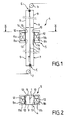
Fig. 1 est une coupe schématique par un plan vertical d'une partie d'une ligne de traitement thermique selon l'invention. -
Fig. 2 est une section schématique suivant la ligne II-II deFig. 1 . -
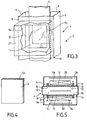
Fig.3 est une vue simplifiée schématique en perspective, à plus grande échelle, avec parties arrachées de la zone du four de traitement correspondant à la section de chauffage, sans inducteur de chauffage ni panneau de fermeture. -
Fig.4 est une vue schématique en perspective d'un panneau de fermeture de la section de chauffage. -
Fig.5 est une vue schématique à plus grande échelle en coupe par un plan horizontal de la section de chauffage, -
Fig.6 est une coupe verticale à plus grande échelle d'une partie de la section de chauffage du four avec un inducteur et son bouclier thermique monté sur une paroi du four. -
Fig. 7 montre, semblablement àFig.6 , une variante de réalisation. -
Fig. 8 est une coupe verticale partielle, à grande échelle, au niveau d'une chicane. -
Fig.9 est une coupe semblable àFig.8 illustrant une variante de chicane. -
Fig.10 est une coupe verticale d'une variante de réalisation au niveau de l'inducteur, et -
Fig. 11 est une coupe verticale d'une autre variante de réalisation. - En se reportant à
Fig.1 des dessins, on peut voir une partie d'une ligne de traitement thermique d'une bande métallique 1, notamment d'une bande d'acier qui défile en continu, à vitesse constante ou variable. Dans l'exemple représenté, la bande 1 se déplace verticalement entre deux rouleaux respectivement inférieur 2 et supérieur 3. Cet exemple n'est pas limitatif, et la bande 1 pourrait défiler horizontalement, les explications qui suivent étant transposables à une telle configuration. - La ligne de traitement comprend un four 4 , généralement à section transversale sensiblement rectangulaire. Le four 4 comporte au moins une section de chauffage 5 équipée, de chaque côté de la bande, d'un demi-inducteur à flux transverse ou pseudo-transverse 11a, 11b. Un couple de demi-inducteurs 11a, 11b constitue un inducteur de chauffage. Selon les caractéristiques de production de la ligne, plusieurs sections de chauffage identiques ou semblables peuvent être placées à la suite les unes des autres sur un même brin vertical ou sur plusieurs brins parallèles. Chaque section de chauffage sera réalisée de façon identique ou similaire aux explications qui suivent.
- Le four 4 est également équipé d'au moins une section de refroidissement 6 en aval de la ou des sections de chauffage, ainsi que d'équipements (non représentés) de contrôle de l'atmosphère à l'intérieur du four. Ces équipement réalisés selon l'état de la technique ne sont pas détaillés ici. Le four 4 constitue un volume fermé, avec des moyens d'étanchéité E à l'entrée et à la sortie de la bande 1, maintenu sous atmosphère de gaz. Le gaz est avantageusement formé par un mélange de gaz inerte, tel que de l'azote, et d'hydrogène, notamment à plus de 5% d'hydrogène en volume pour favoriser les échanges thermiques, et en particulier dans la section de refroidissement 6 qui communique avec la section de chauffage.
- La section de chauffage 5 peut être précédée d'une chambre de traitement 7 assurant, par exemple, un préchauffage.
- Chaque demi-inducteur 11a, 11 b est logé dans une chambre 8a, 8b prévue en saillie vers l'extérieur sur une paroi respective du four. Les parois limitant chaque chambre 8a, 8b établissent une barrière étanche entre le volume intérieur de la chambre et l'atmosphère extérieure.
- Dans la section de chauffage, les parois 9 du four comportent, dans leurs grandes faces en regard, une ouverture 10 en face de chaque demi-inducteur, non représenté sur
Fig.3 . Un panneau 12 transparent au flux magnétique, avec écran thermique 13, couvre, chaque ouverture 10. Les parois du four, généralement en tôle d'acier 9t éventuellement revêtue de réfractaire 9r (Fig.6 et 7 ), se prolongent dans la section de chauffage. Les petites faces et les grandes faces, dont des parties 9a (Fig.3 ) entourent les ouvertures 10, sont ainsi continues suivant la direction verticale, et ne sont pas interrompues suivant toute une section transversale au niveau des inducteurs. Les parois des chambres 8a, 8b autour de chaque demi-inducteur 11a, 11b, peuvent être réalisées par prolongement et mise en forme, avec parties repliées, des parois en tôle 9 du four. - Le panneau 12 est avantageusement plan. Un tel panneau peut être réalisé en matériau composite, résine époxy ou similaire ou en matériau céramique ou en fibres de verre ou en stratifié. Ce type de panneau est particulièrement résistant mécaniquement et thermiquement, et ne présente pas de zones fragiles.
- L'écran thermique 13 peut être constitué, par exemple, comme prévu dans
EP 1 349 431 , par une matrice de pavés (non représentés) en matériau réfractaire qui entoure des tubes de circulation d'eau de refroidissement (non représentés). Les tubes de refroidissement peuvent être réalisés sous forme de serpentins. L'écran thermique 13 est fixé contre la face du panneau 12 tournée vers la bande 1. La face de l'écran thermique 13 tournée vers la bande 1 est de préférence située dans le plan de la face interne de la paroi 9 du four, ou au voisinage de ce plan. Le panneau 12 a généralement une forme rectangulaire, de même que l'ouverture 10. - Bien entendu, la technologie de l'écran thermique 13 est adaptée à la température du produit qui défile. Cette température peut être de 200°C seulement dans le cas de produits autres que des bandes d'acier.
- Le panneau 12 comprend à sa périphérie 14 (voir notamment
Fig.5 et6 ) une forme adaptée à celle de la partie fixe du four entourant l'ouverture 10 de façon à constituer un barrage au rayonnement thermique de la bande vers la chambre, par exemple 8a, logeant l'inducteur, par exemple 11 a. - Avantageusement, un interstice 16 existant entre la périphérie 14 du panneau et le contour de l'ouverture 10 est masqué au rayonnement de la bande 1 par un rebord 15 (
Fig.6 ) de la paroi du four recouvrant l'interstice 16. - Le rebord 15 est situé du côté de la bande 1 et fait saillie vers le centre de l'ouverture 10 relativement au reste 15a de la paroi de l'ouverture qui entoure le panneau 13. Une chicane est ainsi formée définissant un trajet en angle droit comportant une branche, formée par l'interstice 16, orthogonale au plan de la bande 1 et une branche 16a parallèle au plan de la bande 1.
- Le panneau 12 avec son écran thermique 13 peut être fixé, de manière démontable, directement à la paroi du four indépendamment de l'inducteur, comme illustré sur
Fig.5 . La fixation peut être réalisée à l'aide de brides prévues en bordure du panneau et du contour des ouvertures 10, avec boulons de serrage traversant les brides. Les gaz peuvent passer du four vers les chambres 8a, 8b par les interstices 16 comme illustré par des flèches surFig.5 , ou circuler en sens inverse. - Selon une variante avantageuse, l'ensemble du panneau 12 et de l'écran thermique 13 forme un bouclier thermique qui est fixé sur le demi-inducteur, par exemple 11 a, en différents points selon la forme de la face de l'inducteur tournée vers la bande, et contre laquelle est fixé le bouclier thermique. Selon
Fig.6 , le maintien du panneau 12 et de l'écran thermique 13 sur le demi-inducteur est rendu le plus efficace possible en étant réalisé en plusieurs points tels que 17,19 au voisinage des bords et 18 dans la partie centrale. - Le panneau 12 peut être renforcé par des goussets 20, qui en améliorent la tenue mécanique, dans toutes les zones où cela est possible.
- Dans certaines zones, l'épaisseur totale du panneau 12 et de l'écran thermique 13 peut être réduite au minimum autorisé par la technique employée ce qui permet d'augmenter la distance entre les écrans thermiques 13 entre lesquels défile la bande 1.
- La configuration de
Fig.6 permet la réalisation d'un écran renforcé et rigide, formé par l'ensemble du panneau 12 et de l'écran thermique 13 parfaitement maintenu sur le demi-inducteur 11a tout en ayant une épaisseur minimale. - Les
Fig.6 à 9 et10 ne représentent qu'une partie de la section de chauffage située d'un côté de la bande 1. L'autre partie, située de l'autre côté de la bande, est semblable. -
Fig.7 est un développement de la réalisation schématisée surFig.6 , illustrant un montage du demi-inducteur 11a permettant de positionner l'écran thermique 13 et le panneau dans l'ouverture 10 de la paroi du four, en particulier de façon à réaliser une chicane s'opposant à la transmission du rayonnement de la bande 1. Le demi-inducteur 11a est monté sur des galets 21 pouvant rouler sur des rails 22 fixés sur la paroi horizontale inférieure de la chambre 8a et orientés perpendiculairement au plan de la bande 1. La paroi arrière de la chambre 8a comporte une ouverture qui peut être fermée de manière étanche par une porte 23. Pour le montage, la porte 23 est retirée ce qui permet d'introduire le demi-inducteur 11a, muni de son bouclier thermique, dans la chambre 8a par une translation perpendiculaire au plan de la bande 1 suivant la direction de la flèche F. Des butées garantissent le bon positionnement de l'ensemble du panneau 12 et de l'écran thermique 13 et ainsi l'efficacité de la chicane 16,16a. Après mise en place du demi-inducteur avec son bouclier thermique, la porte 23 est fixée de manière étanche sur la paroi arrière de la chambre 8a. - La chicane formée peut avoir une forme plus complexe comme illustrée sur les
Fig. 8, 9 et10 . -
Fig. 8 illustre une réalisation particulière de la chicane permettant de renforcer le barrage contre le rayonnement de la bande. - A cet effet, la périphérie du panneau 12 comporte un rebord 24, par exemple à section rectangulaire, en saillie en direction de la bande 1. Le rebord 15 de la paroi du four comporte un retour 15a en saillie vers le panneau 12 et délimite une gorge dans laquelle le rebord 24 vient s'inscrire. La chicane complexe ainsi formée comporte une première partie 16b parallèle à la bande 1, suivie d'une partie 16c orthogonale à la bande 1 puis de la partie 16a parallèle à la bande 1 et enfin de l'interstice 16.
- Toutes les parties de la chicane sont protégées contre un rayonnement thermique direct de la bande 1 par le rebord 15 et son retour 15a.
- Le montage du demi-inducteur 11a, selon la réalisation de
Fig.8 , s'effectue de la même manière que celle exposée à propos deFig. 7 par un déplacement suivant une direction F orthogonale au plan de la bande 1. - On peut considérer que l'écran présente une forme particulière sur ses quatre bords de façon à obtenir une chicane plus importante ou l'assemblage de plusieurs chicanes destinées à améliorer leur efficacité à stopper le rayonnement de la bande.
- On peut également considérer que les chicanes sont garnies, par exemple, d'un réfractaire fibreux facilement déformable durant le montage de l'écran et assurant l'arrêt total du rayonnement de la bande, sans toutefois assurer l'étanchéité au gaz entre le volume intérieur du four et la chambre du demi-inducteur.
-
Fig. 9 présente une variante de réalisation de la chicane destinée à stopper le rayonnement de la bande. Le contour du panneau 12 présente un bord 25 en saillie vers le demi-inducteur 11 a. Le contour de l'ouverture 10 de la paroi du four présente un retour 26 vers l'extérieur délimitant une gorge en angle droit dans laquelle vient se loger le bord 25 pour former une chicane avec branche horizontale 16 s'ouvrant dans le four suivie d'une branche 16a parallèle à la bande 1 et s'ouvrant dans la chambre 8a. La mise en place de chaque demi-inducteur s'effectue par une translation parallèle au plan de la bande 1. -
Fig. 10 présente une autre variante de réalisation de la chicane suivant le mode de montage du demi-inducteur par déplacement parallèle au plan de la bande. La chicane 26 a la forme d'une grecque avec nervures et rainures horizontales dans l'épaisseur des parois du four et de l'écran, permettant un engagement et un dégagement par translation horizontale parallèle à la bande. -
Fig.11 présente le montage des demi-inducteurs 11 a, 11 b de part et d'autre de la bande 1. - Une arrivée 27 de gaz est prévue dans au moins une des chambres, par exemple 8b, si elle communique avec l'autre chambre 8a, ou bien une arrivée de gaz est prévue dans chacune des deux chambres 8a, 8b si elles ne communiquent pas. La température du gaz injecté est suffisamment faible pour maintenir les chambres 8a, 8b à une température acceptable de fonctionnement, par exemple 50°C
- On peut ajuster la pression de gaz injecté dans chaque chambre 8a, 8b à un niveau légèrement supérieur à celui régnant dans le four afin que la circulation de gaz au niveau de la chicane 16, 16a four/écran s'opère de la chambre vers le four et non l'inverse. On évite ainsi la pénétration de gaz chauds, provenant du four, vers l'intérieur de la chambre.
- On peut utiliser comme gaz injecté dans les chambres 8a, 8b la même composition de gaz que celle existant à l'intérieur du four ou un mélange différent afin, par exemple, d'enrichir l'ambiance du four avec un composant du procédé de traitement. Par exemple pour une atmosphère formée par un mélange azote (N2) et hydrogène (H2), on peut établir une pressurisation des chambres 8a, 8b avec une composition plus riche en H2 que l'ambiance du four ou, au contraire plus riche en N2 , dans le but de corriger la concentration de l'intérieur du four.
- La limitation de la température régnant dans les chambres 8a, 8b peut aussi être obtenue sans injection de gaz froid, notamment grâce à un circuit de refroidissement de l'inducteur ou grâce à un échangeur supplémentaire 28 (
Fig.5 ) installé dans les chambres 8a, 8b, et comportant par exemple des serpentins dans lesquels circulent de l'eau de refroidissement. - La dimension des écrans thermiques est définie en fonction des caractéristiques magnétiques de l'inducteur et du passage des lignes de champ afin d'assurer leur totale transparence à l'ensemble du flux magnétique et afin d'éviter tout risque d'échauffement des parties métalliques des parois 9 situées autour des écrans et constituant le four traditionnel.
- Le volume interne des sections de chauffage et de refroidissement ainsi que le volume interne des chambres 8a, 8b est bien protégé contre les entrées éventuelles d'air et d'oxygène, notamment grâce à une surpression du mélange d'hydrogène et d'azote vis-à-vis de l'atmosphère ambiante.
- La description qui précède a été effectuée principalement à propos d'une bande 1 continue. L'invention s'applique également à d'autres produits espacés les uns des autres tels que des tôles ou des plaques, ou similaires, en matériau conducteur de l'électricité, qui défilent à vitesse constante ou variable.
Claims (14)
- Four de traitement thermique de bandes, tôles, plaques en matériau conducteur de l'électricité, notamment métalliques, qui défilent dans le four constitué d'un volume fermé maintenu sous une atmosphère de gaz, lequel comporte une section de chauffage avec au moins un inducteur formé d'un couple de demi-inducteurs à flux transverse ou pseudo-transverse, caractérisé en ce que, dans la section de chauffage (5), au moins deux parois (9) du four comportent chacune une ouverture (10) en face de chacun des deux demi-inducteurs (11a, 11 b) et deux panneaux (12) transparents au flux magnétique couvrent respectivement lesdites ouvertures (10), ces panneaux (12) comprenant à leur périphérie (14) une forme adaptée à celle de la partie fixe du four entourant chaque ouverture de façon à constituer un barrage au rayonnement thermique de la bande sans assurer une étanchéité au gaz, et chaque demi-inducteur (11 a, 11 b) est logé dans une chambre (8a, 8b) délimitée par des parois en saillie vers l'extérieur du four, ces chambres étant isolées de manière étanche de l'atmosphère ambiante mais communiquant avec le volume intérieur du four.
- Four selon la revendication 1, caractérisé en ce que chaque panneau transparent au flux magnétique est muni d'un écran thermique (13).
- Four selon la revendication 2, caractérisé en ce que les panneaux transparents au flux magnétique (12), avec écran thermique (13), forment chacun un bouclier thermique qui est fixé sur le demi-inducteur associé (11a, 11 b).
- Four selon la revendication 2, caractérisé en ce que les panneaux transparents au flux magnétique (12), avec écran thermique (13), sont fixés à la paroi (9) du four, et sont indépendants des demi-inducteurs.
- Four selon l'une des revendications précédentes, caractérisé en ce que la face de l'écran thermique (13) tournée vers la bande (1) est sensiblement dans le même plan que la face interne de la paroi du four.
- Four selon l'une des revendications précédentes, caractérisé en ce qu'il comporte une chicane (16, 16a ; 16b, 16c ; 26), en particulier double ou de forme plus complexe, entre la périphérie (14) du panneau et le bord de l'ouverture (10) de la paroi du four pour réduire la transmission du rayonnement de la bande.
- Four selon la revendication 6, caractérisé en ce que des matières fibreuses sont mises en place dans la chicane pour réduire la transmission du rayonnement de la bande sans assurer l'étanchéité au gaz entre le four et les chambres contenant les demi-inducteurs.
- Four selon l'une des revendications précédentes, caractérisé en ce qu'une atmosphère de même nature que celle du four règne dans les chambres (8a, 8b) contenant les demi-inducteurs (11 a, 11b).
- Four selon la revendication 8, caractérisé en ce que l'atmosphère du four et celle des chambres (8a, 8b) est formée d'un mélange de gaz inerte et d'hydrogène à plus de 5% en volume.
- Four selon la revendication 6 ou 7, caractérisé en ce que le montage de chaque demi-inducteur (11a, 11 b) s'opère de façon à ce que l'écran thermique vienne s'encastrer dans des chicanes prévues en bordure de l'ouverture et destinées à réduire la transmission du rayonnement de la bande.
- Four selon l'une des revendications précédentes, caractérisé en ce qu'il comporte des moyens de guidage et des moyens de support (22) de chaque demi-inducteur pour un montage suivant une translation perpendiculaire à la bande (1).
- Four selon l'une des revendications 1 à 10, caractérisé en ce qu'il comporte des moyens de guidage et des moyens de support de chaque demi-inducteur pour un montage suivant une translation parallèle à la bande (1).
- Four selon l'une des revendications précédentes, caractérisé en ce qu'il comporte des moyens d'injection (27) d'un gaz correspondant à, ou compatible avec, l'atmosphère du four, dans les chambres (8a,8b) contenant les demi-inducteurs (11a, 11 b) à une pression légèrement supérieure à celle du four pour éviter la pénétration de gaz chauds du four dans les chambres (8a, 8b).
- Inducteur à flux transverse formé de deux demi-inducteurs, pour un four selon la revendication 2, caractérisé en ce que sur chaque demi-inducteur (11a, 11b) est fixé un bouclier thermique (12, 13), transparent au flux magnétique, comprenant à sa périphérie (14) une forme adaptée à celle de bords fixes d'une ouverture (10) dans une paroi du four de façon à constituer un barrage au rayonnement thermique de la bande vers les chambres dans lesquelles sont placés les demi-inducteurs, l'ensemble étant placé dans une atmosphère de nature compatible avec celle du four.
Applications Claiming Priority (2)
| Application Number | Priority Date | Filing Date | Title |
|---|---|---|---|
| FR0506463A FR2887738B1 (fr) | 2005-06-24 | 2005-06-24 | Four a induction pour traitement de bandes, toles, plaques, en materiau conducteur de l'electricite, et inducteur pour un tel four |
| PCT/FR2006/001402 WO2006136701A1 (fr) | 2005-06-24 | 2006-06-21 | Four a induction pour traitement de bandes, toles, plaques, en materiau conducteur de l'electricite, et inducteur pour un tel four. |
Publications (3)
| Publication Number | Publication Date |
|---|---|
| EP1900255A1 EP1900255A1 (fr) | 2008-03-19 |
| EP1900255B1 true EP1900255B1 (fr) | 2008-12-03 |
| EP1900255B8 EP1900255B8 (fr) | 2009-03-25 |
Family
ID=35708648
Family Applications (1)
| Application Number | Title | Priority Date | Filing Date |
|---|---|---|---|
| EP06778631A Not-in-force EP1900255B8 (fr) | 2005-06-24 | 2006-06-21 | Four a induction pour traitement de bandes, toles, plaques, en materiau conducteur de l'electricite, et inducteur pour un tel four. |
Country Status (6)
| Country | Link |
|---|---|
| EP (1) | EP1900255B8 (fr) |
| AT (1) | ATE416594T1 (fr) |
| DE (1) | DE602006004052D1 (fr) |
| ES (1) | ES2318784T3 (fr) |
| FR (1) | FR2887738B1 (fr) |
| WO (1) | WO2006136701A1 (fr) |
Cited By (1)
| Publication number | Priority date | Publication date | Assignee | Title |
|---|---|---|---|---|
| EP4271129A1 (fr) * | 2022-04-29 | 2023-11-01 | SMS Elotherm GmbH | Dispositif de chauffage par induction d'au moins une pièce, ainsi que procédé de chauffage par induction d'au moins une pièce |
Families Citing this family (1)
| Publication number | Priority date | Publication date | Assignee | Title |
|---|---|---|---|---|
| CN115948647B (zh) * | 2023-02-10 | 2023-07-18 | 中建五洲工程装备有限公司 | 一种针对钢箱梁顶板u肋现场对接焊缝的热处理设备 |
Family Cites Families (4)
| Publication number | Priority date | Publication date | Assignee | Title |
|---|---|---|---|---|
| US5958273A (en) * | 1994-02-01 | 1999-09-28 | E. I. Du Pont De Nemours And Company | Induction heated reactor apparatus |
| SE515593C2 (sv) * | 1999-03-01 | 2001-09-03 | Avesta Sheffield Ab | Apparat för värmning av ett metallband |
| EP1178134A1 (fr) * | 2000-08-04 | 2002-02-06 | Cold Plasma Applications C.P.A. | Procédé et dispositif pour traiter des substrats métalliques au défilé par plasma |
| US6570141B2 (en) * | 2001-03-26 | 2003-05-27 | Nicholas V. Ross | Transverse flux induction heating of conductive strip |
-
2005
- 2005-06-24 FR FR0506463A patent/FR2887738B1/fr not_active Expired - Fee Related
-
2006
- 2006-06-21 WO PCT/FR2006/001402 patent/WO2006136701A1/fr not_active Ceased
- 2006-06-21 AT AT06778631T patent/ATE416594T1/de not_active IP Right Cessation
- 2006-06-21 EP EP06778631A patent/EP1900255B8/fr not_active Not-in-force
- 2006-06-21 ES ES06778631T patent/ES2318784T3/es active Active
- 2006-06-21 DE DE602006004052T patent/DE602006004052D1/de active Active
Cited By (2)
| Publication number | Priority date | Publication date | Assignee | Title |
|---|---|---|---|---|
| EP4271129A1 (fr) * | 2022-04-29 | 2023-11-01 | SMS Elotherm GmbH | Dispositif de chauffage par induction d'au moins une pièce, ainsi que procédé de chauffage par induction d'au moins une pièce |
| WO2023208805A1 (fr) * | 2022-04-29 | 2023-11-02 | Sms Elotherm Gmbh | Dispositif de chauffage inductif d'au moins une pièce et procédé de chauffage inductif d'au moins une pièce |
Also Published As
| Publication number | Publication date |
|---|---|
| EP1900255B8 (fr) | 2009-03-25 |
| DE602006004052D1 (de) | 2009-01-15 |
| ES2318784T3 (es) | 2009-05-01 |
| FR2887738A1 (fr) | 2006-12-29 |
| WO2006136701A1 (fr) | 2006-12-28 |
| ATE416594T1 (de) | 2008-12-15 |
| EP1900255A1 (fr) | 2008-03-19 |
| FR2887738B1 (fr) | 2007-08-24 |
Similar Documents
| Publication | Publication Date | Title |
|---|---|---|
| EP0822733B1 (fr) | Dispositif de chauffage par induction et installation de traitement thermique en continu comportant un tel dispositif | |
| JP2004538373A (ja) | 化学蒸着システム | |
| EP2513582A1 (fr) | Installation et procédé de préchauffage d'une bande d'acier en défilement continu | |
| EP0744222B1 (fr) | Procédé de revêtement de bandes métalliques | |
| EP1900255B1 (fr) | Four a induction pour traitement de bandes, toles, plaques, en materiau conducteur de l'electricite, et inducteur pour un tel four. | |
| FR2950079A1 (fr) | Dispositif de chauffage pour traitement thermique local | |
| WO2001042542A1 (fr) | Boite d'etancheite pour une enceinte de traitement en continu de produit mince en bande | |
| EP1627096B1 (fr) | Sas d'etancheite pour ligne de depot sous vide sur produit plat | |
| WO2006136702A1 (fr) | Four a induction pour traiter des bandes, toles, plaques, en materiau conducteur de l'electricite, et inducteur pour un tel four. | |
| FR2569202A1 (fr) | Sas equipant des installations a fours de recuit | |
| EP3063313A1 (fr) | Dispositif d'étanchéité pour capot de cellule d'électrolyse | |
| EP1899493A1 (fr) | Dispositif et procede de guidage d'une bande metallique dans des equipements de traitement en continu. | |
| EP1969149B1 (fr) | Ecran d'isolation thermique pour isoler un inducteur electromagnetique, et installation de traitement thermique comportant un tel ecran. | |
| EP3397786B1 (fr) | Dispositif et procede pour realiser une oxydation controlee de bandes metalliques dans un four de traitement en continu | |
| FR2666405A1 (fr) | Dispositif d'etancheite laterale deformable pour fours. | |
| EP0913658B2 (fr) | Système de sécurité pour fours ayant un refroidissement à gaz pour bande métallique | |
| FR2630533A1 (fr) | Enceinte thermique | |
| WO2024200828A1 (fr) | Four verrier | |
| FR2664032A1 (fr) | Four a rouleaux. | |
| EP2173918B1 (fr) | Installation de revetement d'une bande metallique | |
| FR2747594A1 (fr) | Procede et installation d'elaboration d'une atmosphere de traitement thermique |
Legal Events
| Date | Code | Title | Description |
|---|---|---|---|
| PUAI | Public reference made under article 153(3) epc to a published international application that has entered the european phase |
Free format text: ORIGINAL CODE: 0009012 |
|
| 17P | Request for examination filed |
Effective date: 20071231 |
|
| AK | Designated contracting states |
Kind code of ref document: A1 Designated state(s): AT BE BG CH CY CZ DE DK EE ES FI FR GB GR HU IE IS IT LI LT LU LV MC NL PL PT RO SE SI SK TR |
|
| DAX | Request for extension of the european patent (deleted) | ||
| GRAP | Despatch of communication of intention to grant a patent |
Free format text: ORIGINAL CODE: EPIDOSNIGR1 |
|
| DAX | Request for extension of the european patent (deleted) | ||
| GRAS | Grant fee paid |
Free format text: ORIGINAL CODE: EPIDOSNIGR3 |
|
| GRAA | (expected) grant |
Free format text: ORIGINAL CODE: 0009210 |
|
| AK | Designated contracting states |
Kind code of ref document: B1 Designated state(s): AT BE BG CH CY CZ DE DK EE ES FI FR GB GR HU IE IS IT LI LT LU LV MC NL PL PT RO SE SI SK TR |
|
| REG | Reference to a national code |
Ref country code: GB Ref legal event code: FG4D Free format text: NOT ENGLISH |
|
| REG | Reference to a national code |
Ref country code: CH Ref legal event code: EP |
|
| RAP2 | Party data changed (patent owner data changed or rights of a patent transferred) |
Owner name: FIVES CELES |
|
| REG | Reference to a national code |
Ref country code: IE Ref legal event code: FG4D Free format text: LANGUAGE OF EP DOCUMENT: FRENCH |
|
| REF | Corresponds to: |
Ref document number: 602006004052 Country of ref document: DE Date of ref document: 20090115 Kind code of ref document: P |
|
| NLT2 | Nl: modifications (of names), taken from the european patent patent bulletin |
Owner name: FIVES CELES Effective date: 20090107 |
|
| PG25 | Lapsed in a contracting state [announced via postgrant information from national office to epo] |
Ref country code: LT Free format text: LAPSE BECAUSE OF FAILURE TO SUBMIT A TRANSLATION OF THE DESCRIPTION OR TO PAY THE FEE WITHIN THE PRESCRIBED TIME-LIMIT Effective date: 20081203 |
|
| REG | Reference to a national code |
Ref country code: ES Ref legal event code: FG2A Ref document number: 2318784 Country of ref document: ES Kind code of ref document: T3 |
|
| NLV1 | Nl: lapsed or annulled due to failure to fulfill the requirements of art. 29p and 29m of the patents act | ||
| PG25 | Lapsed in a contracting state [announced via postgrant information from national office to epo] |
Ref country code: PL Free format text: LAPSE BECAUSE OF FAILURE TO SUBMIT A TRANSLATION OF THE DESCRIPTION OR TO PAY THE FEE WITHIN THE PRESCRIBED TIME-LIMIT Effective date: 20081203 Ref country code: SI Free format text: LAPSE BECAUSE OF FAILURE TO SUBMIT A TRANSLATION OF THE DESCRIPTION OR TO PAY THE FEE WITHIN THE PRESCRIBED TIME-LIMIT Effective date: 20081203 Ref country code: LV Free format text: LAPSE BECAUSE OF FAILURE TO SUBMIT A TRANSLATION OF THE DESCRIPTION OR TO PAY THE FEE WITHIN THE PRESCRIBED TIME-LIMIT Effective date: 20081203 Ref country code: NL Free format text: LAPSE BECAUSE OF FAILURE TO SUBMIT A TRANSLATION OF THE DESCRIPTION OR TO PAY THE FEE WITHIN THE PRESCRIBED TIME-LIMIT Effective date: 20081203 |
|
| REG | Reference to a national code |
Ref country code: IE Ref legal event code: FD4D |
|
| PG25 | Lapsed in a contracting state [announced via postgrant information from national office to epo] |
Ref country code: RO Free format text: LAPSE BECAUSE OF FAILURE TO SUBMIT A TRANSLATION OF THE DESCRIPTION OR TO PAY THE FEE WITHIN THE PRESCRIBED TIME-LIMIT Effective date: 20081203 Ref country code: IE Free format text: LAPSE BECAUSE OF FAILURE TO SUBMIT A TRANSLATION OF THE DESCRIPTION OR TO PAY THE FEE WITHIN THE PRESCRIBED TIME-LIMIT Effective date: 20081203 Ref country code: BG Free format text: LAPSE BECAUSE OF FAILURE TO SUBMIT A TRANSLATION OF THE DESCRIPTION OR TO PAY THE FEE WITHIN THE PRESCRIBED TIME-LIMIT Effective date: 20090303 Ref country code: EE Free format text: LAPSE BECAUSE OF FAILURE TO SUBMIT A TRANSLATION OF THE DESCRIPTION OR TO PAY THE FEE WITHIN THE PRESCRIBED TIME-LIMIT Effective date: 20081203 |
|
| PG25 | Lapsed in a contracting state [announced via postgrant information from national office to epo] |
Ref country code: AT Free format text: LAPSE BECAUSE OF FAILURE TO SUBMIT A TRANSLATION OF THE DESCRIPTION OR TO PAY THE FEE WITHIN THE PRESCRIBED TIME-LIMIT Effective date: 20081203 Ref country code: PT Free format text: LAPSE BECAUSE OF FAILURE TO SUBMIT A TRANSLATION OF THE DESCRIPTION OR TO PAY THE FEE WITHIN THE PRESCRIBED TIME-LIMIT Effective date: 20090504 Ref country code: SE Free format text: LAPSE BECAUSE OF FAILURE TO SUBMIT A TRANSLATION OF THE DESCRIPTION OR TO PAY THE FEE WITHIN THE PRESCRIBED TIME-LIMIT Effective date: 20090303 Ref country code: IS Free format text: LAPSE BECAUSE OF FAILURE TO SUBMIT A TRANSLATION OF THE DESCRIPTION OR TO PAY THE FEE WITHIN THE PRESCRIBED TIME-LIMIT Effective date: 20090403 Ref country code: CZ Free format text: LAPSE BECAUSE OF FAILURE TO SUBMIT A TRANSLATION OF THE DESCRIPTION OR TO PAY THE FEE WITHIN THE PRESCRIBED TIME-LIMIT Effective date: 20081203 |
|
| PG25 | Lapsed in a contracting state [announced via postgrant information from national office to epo] |
Ref country code: SK Free format text: LAPSE BECAUSE OF FAILURE TO SUBMIT A TRANSLATION OF THE DESCRIPTION OR TO PAY THE FEE WITHIN THE PRESCRIBED TIME-LIMIT Effective date: 20081203 |
|
| PLBE | No opposition filed within time limit |
Free format text: ORIGINAL CODE: 0009261 |
|
| STAA | Information on the status of an ep patent application or granted ep patent |
Free format text: STATUS: NO OPPOSITION FILED WITHIN TIME LIMIT |
|
| PG25 | Lapsed in a contracting state [announced via postgrant information from national office to epo] |
Ref country code: DK Free format text: LAPSE BECAUSE OF FAILURE TO SUBMIT A TRANSLATION OF THE DESCRIPTION OR TO PAY THE FEE WITHIN THE PRESCRIBED TIME-LIMIT Effective date: 20081203 |
|
| 26N | No opposition filed |
Effective date: 20090904 |
|
| PG25 | Lapsed in a contracting state [announced via postgrant information from national office to epo] |
Ref country code: MC Free format text: LAPSE BECAUSE OF NON-PAYMENT OF DUE FEES Effective date: 20090630 |
|
| PG25 | Lapsed in a contracting state [announced via postgrant information from national office to epo] |
Ref country code: GR Free format text: LAPSE BECAUSE OF FAILURE TO SUBMIT A TRANSLATION OF THE DESCRIPTION OR TO PAY THE FEE WITHIN THE PRESCRIBED TIME-LIMIT Effective date: 20090304 |
|
| REG | Reference to a national code |
Ref country code: CH Ref legal event code: PL |
|
| GBPC | Gb: european patent ceased through non-payment of renewal fee |
Effective date: 20100621 |
|
| PG25 | Lapsed in a contracting state [announced via postgrant information from national office to epo] |
Ref country code: LI Free format text: LAPSE BECAUSE OF NON-PAYMENT OF DUE FEES Effective date: 20090630 Ref country code: CH Free format text: LAPSE BECAUSE OF NON-PAYMENT OF DUE FEES Effective date: 20090630 |
|
| PG25 | Lapsed in a contracting state [announced via postgrant information from national office to epo] |
Ref country code: CH Free format text: LAPSE BECAUSE OF NON-PAYMENT OF DUE FEES Effective date: 20100630 Ref country code: LI Free format text: LAPSE BECAUSE OF NON-PAYMENT OF DUE FEES Effective date: 20100630 Ref country code: LU Free format text: LAPSE BECAUSE OF NON-PAYMENT OF DUE FEES Effective date: 20090621 |
|
| PG25 | Lapsed in a contracting state [announced via postgrant information from national office to epo] |
Ref country code: HU Free format text: LAPSE BECAUSE OF FAILURE TO SUBMIT A TRANSLATION OF THE DESCRIPTION OR TO PAY THE FEE WITHIN THE PRESCRIBED TIME-LIMIT Effective date: 20090604 |
|
| PG25 | Lapsed in a contracting state [announced via postgrant information from national office to epo] |
Ref country code: GB Free format text: LAPSE BECAUSE OF NON-PAYMENT OF DUE FEES Effective date: 20100621 |
|
| PG25 | Lapsed in a contracting state [announced via postgrant information from national office to epo] |
Ref country code: TR Free format text: LAPSE BECAUSE OF FAILURE TO SUBMIT A TRANSLATION OF THE DESCRIPTION OR TO PAY THE FEE WITHIN THE PRESCRIBED TIME-LIMIT Effective date: 20081203 |
|
| PG25 | Lapsed in a contracting state [announced via postgrant information from national office to epo] |
Ref country code: CY Free format text: LAPSE BECAUSE OF FAILURE TO SUBMIT A TRANSLATION OF THE DESCRIPTION OR TO PAY THE FEE WITHIN THE PRESCRIBED TIME-LIMIT Effective date: 20081203 |
|
| PGFP | Annual fee paid to national office [announced via postgrant information from national office to epo] |
Ref country code: ES Payment date: 20120614 Year of fee payment: 7 |
|
| PGFP | Annual fee paid to national office [announced via postgrant information from national office to epo] |
Ref country code: DE Payment date: 20130523 Year of fee payment: 8 |
|
| PGFP | Annual fee paid to national office [announced via postgrant information from national office to epo] |
Ref country code: IT Payment date: 20130523 Year of fee payment: 8 Ref country code: FI Payment date: 20130523 Year of fee payment: 8 Ref country code: BE Payment date: 20130523 Year of fee payment: 8 |
|
| REG | Reference to a national code |
Ref country code: DE Ref legal event code: R119 Ref document number: 602006004052 Country of ref document: DE |
|
| PG25 | Lapsed in a contracting state [announced via postgrant information from national office to epo] |
Ref country code: FI Free format text: LAPSE BECAUSE OF NON-PAYMENT OF DUE FEES Effective date: 20140621 |
|
| PG25 | Lapsed in a contracting state [announced via postgrant information from national office to epo] |
Ref country code: IT Free format text: LAPSE BECAUSE OF NON-PAYMENT OF DUE FEES Effective date: 20140621 Ref country code: DE Free format text: LAPSE BECAUSE OF NON-PAYMENT OF DUE FEES Effective date: 20150101 |
|
| REG | Reference to a national code |
Ref country code: DE Ref legal event code: R119 Ref document number: 602006004052 Country of ref document: DE Effective date: 20150101 |
|
| REG | Reference to a national code |
Ref country code: FR Ref legal event code: PLFP Year of fee payment: 10 |
|
| REG | Reference to a national code |
Ref country code: ES Ref legal event code: FD2A Effective date: 20150724 |
|
| PG25 | Lapsed in a contracting state [announced via postgrant information from national office to epo] |
Ref country code: ES Free format text: LAPSE BECAUSE OF NON-PAYMENT OF DUE FEES Effective date: 20140622 |
|
| REG | Reference to a national code |
Ref country code: FR Ref legal event code: PLFP Year of fee payment: 11 |
|
| REG | Reference to a national code |
Ref country code: FR Ref legal event code: PLFP Year of fee payment: 12 |
|
| PG25 | Lapsed in a contracting state [announced via postgrant information from national office to epo] |
Ref country code: BE Free format text: LAPSE BECAUSE OF NON-PAYMENT OF DUE FEES Effective date: 20140630 |
|
| REG | Reference to a national code |
Ref country code: FR Ref legal event code: PLFP Year of fee payment: 13 |
|
| PGFP | Annual fee paid to national office [announced via postgrant information from national office to epo] |
Ref country code: FR Payment date: 20230523 Year of fee payment: 18 |
|
| PG25 | Lapsed in a contracting state [announced via postgrant information from national office to epo] |
Ref country code: FR Free format text: LAPSE BECAUSE OF NON-PAYMENT OF DUE FEES Effective date: 20240630 |