EP1900499B1 - Vorrichtung zum kontinuierlichen Verbinden und/oder Verfestigen von Materialbahnen mittels Ultraschall - Google Patents
Vorrichtung zum kontinuierlichen Verbinden und/oder Verfestigen von Materialbahnen mittels Ultraschall Download PDFInfo
- Publication number
- EP1900499B1 EP1900499B1 EP07021514A EP07021514A EP1900499B1 EP 1900499 B1 EP1900499 B1 EP 1900499B1 EP 07021514 A EP07021514 A EP 07021514A EP 07021514 A EP07021514 A EP 07021514A EP 1900499 B1 EP1900499 B1 EP 1900499B1
- Authority
- EP
- European Patent Office
- Prior art keywords
- rotating roller
- roller
- rotating
- counter
- amplitude transformer
- Prior art date
- Legal status (The legal status is an assumption and is not a legal conclusion. Google has not performed a legal analysis and makes no representation as to the accuracy of the status listed.)
- Expired - Lifetime
Links
- 239000000463 material Substances 0.000 title claims description 16
- 230000010355 oscillation Effects 0.000 claims abstract description 10
- 238000003466 welding Methods 0.000 claims description 5
- 238000005452 bending Methods 0.000 claims description 2
- 230000008961 swelling Effects 0.000 claims 1
- 230000009466 transformation Effects 0.000 description 12
- 238000007711 solidification Methods 0.000 description 4
- 230000008023 solidification Effects 0.000 description 4
- 238000010438 heat treatment Methods 0.000 description 2
- 239000011324 bead Substances 0.000 description 1
- 230000000694 effects Effects 0.000 description 1
- 238000000265 homogenisation Methods 0.000 description 1
- 230000002093 peripheral effect Effects 0.000 description 1
- 230000001105 regulatory effect Effects 0.000 description 1
- 238000002604 ultrasonography Methods 0.000 description 1
- 235000012773 waffles Nutrition 0.000 description 1
Images




Classifications
-
- B—PERFORMING OPERATIONS; TRANSPORTING
- B29—WORKING OF PLASTICS; WORKING OF SUBSTANCES IN A PLASTIC STATE IN GENERAL
- B29C—SHAPING OR JOINING OF PLASTICS; SHAPING OF MATERIAL IN A PLASTIC STATE, NOT OTHERWISE PROVIDED FOR; AFTER-TREATMENT OF THE SHAPED PRODUCTS, e.g. REPAIRING
- B29C66/00—General aspects of processes or apparatus for joining preformed parts
- B29C66/80—General aspects of machine operations or constructions and parts thereof
- B29C66/83—General aspects of machine operations or constructions and parts thereof characterised by the movement of the joining or pressing tools
- B29C66/834—General aspects of machine operations or constructions and parts thereof characterised by the movement of the joining or pressing tools moving with the parts to be joined
- B29C66/8341—Roller, cylinder or drum types; Band or belt types; Ball types
- B29C66/83411—Roller, cylinder or drum types
- B29C66/83413—Roller, cylinder or drum types cooperating rollers, cylinders or drums
-
- B—PERFORMING OPERATIONS; TRANSPORTING
- B23—MACHINE TOOLS; METAL-WORKING NOT OTHERWISE PROVIDED FOR
- B23K—SOLDERING OR UNSOLDERING; WELDING; CLADDING OR PLATING BY SOLDERING OR WELDING; CUTTING BY APPLYING HEAT LOCALLY, e.g. FLAME CUTTING; WORKING BY LASER BEAM
- B23K20/00—Non-electric welding by applying impact or other pressure, with or without the application of heat, e.g. cladding or plating
- B23K20/10—Non-electric welding by applying impact or other pressure, with or without the application of heat, e.g. cladding or plating making use of vibrations, e.g. ultrasonic welding
- B23K20/103—Non-electric welding by applying impact or other pressure, with or without the application of heat, e.g. cladding or plating making use of vibrations, e.g. ultrasonic welding using a roller
-
- B—PERFORMING OPERATIONS; TRANSPORTING
- B29—WORKING OF PLASTICS; WORKING OF SUBSTANCES IN A PLASTIC STATE IN GENERAL
- B29C—SHAPING OR JOINING OF PLASTICS; SHAPING OF MATERIAL IN A PLASTIC STATE, NOT OTHERWISE PROVIDED FOR; AFTER-TREATMENT OF THE SHAPED PRODUCTS, e.g. REPAIRING
- B29C65/00—Joining or sealing of preformed parts, e.g. welding of plastics materials; Apparatus therefor
- B29C65/02—Joining or sealing of preformed parts, e.g. welding of plastics materials; Apparatus therefor by heating, with or without pressure
- B29C65/08—Joining or sealing of preformed parts, e.g. welding of plastics materials; Apparatus therefor by heating, with or without pressure using ultrasonic vibrations
- B29C65/083—Joining or sealing of preformed parts, e.g. welding of plastics materials; Apparatus therefor by heating, with or without pressure using ultrasonic vibrations using a rotary sonotrode or a rotary anvil
- B29C65/087—Joining or sealing of preformed parts, e.g. welding of plastics materials; Apparatus therefor by heating, with or without pressure using ultrasonic vibrations using a rotary sonotrode or a rotary anvil using both a rotary sonotrode and a rotary anvil
-
- B—PERFORMING OPERATIONS; TRANSPORTING
- B29—WORKING OF PLASTICS; WORKING OF SUBSTANCES IN A PLASTIC STATE IN GENERAL
- B29C—SHAPING OR JOINING OF PLASTICS; SHAPING OF MATERIAL IN A PLASTIC STATE, NOT OTHERWISE PROVIDED FOR; AFTER-TREATMENT OF THE SHAPED PRODUCTS, e.g. REPAIRING
- B29C66/00—General aspects of processes or apparatus for joining preformed parts
- B29C66/01—General aspects dealing with the joint area or with the area to be joined
- B29C66/05—Particular design of joint configurations
- B29C66/10—Particular design of joint configurations particular design of the joint cross-sections
- B29C66/11—Joint cross-sections comprising a single joint-segment, i.e. one of the parts to be joined comprising a single joint-segment in the joint cross-section
- B29C66/112—Single lapped joints
- B29C66/1122—Single lap to lap joints, i.e. overlap joints
-
- B—PERFORMING OPERATIONS; TRANSPORTING
- B29—WORKING OF PLASTICS; WORKING OF SUBSTANCES IN A PLASTIC STATE IN GENERAL
- B29C—SHAPING OR JOINING OF PLASTICS; SHAPING OF MATERIAL IN A PLASTIC STATE, NOT OTHERWISE PROVIDED FOR; AFTER-TREATMENT OF THE SHAPED PRODUCTS, e.g. REPAIRING
- B29C66/00—General aspects of processes or apparatus for joining preformed parts
- B29C66/40—General aspects of joining substantially flat articles, e.g. plates, sheets or web-like materials; Making flat seams in tubular or hollow articles; Joining single elements to substantially flat surfaces
- B29C66/41—Joining substantially flat articles ; Making flat seams in tubular or hollow articles
- B29C66/43—Joining a relatively small portion of the surface of said articles
-
- B—PERFORMING OPERATIONS; TRANSPORTING
- B29—WORKING OF PLASTICS; WORKING OF SUBSTANCES IN A PLASTIC STATE IN GENERAL
- B29C—SHAPING OR JOINING OF PLASTICS; SHAPING OF MATERIAL IN A PLASTIC STATE, NOT OTHERWISE PROVIDED FOR; AFTER-TREATMENT OF THE SHAPED PRODUCTS, e.g. REPAIRING
- B29C66/00—General aspects of processes or apparatus for joining preformed parts
- B29C66/40—General aspects of joining substantially flat articles, e.g. plates, sheets or web-like materials; Making flat seams in tubular or hollow articles; Joining single elements to substantially flat surfaces
- B29C66/41—Joining substantially flat articles ; Making flat seams in tubular or hollow articles
- B29C66/45—Joining of substantially the whole surface of the articles
-
- B—PERFORMING OPERATIONS; TRANSPORTING
- B29—WORKING OF PLASTICS; WORKING OF SUBSTANCES IN A PLASTIC STATE IN GENERAL
- B29C—SHAPING OR JOINING OF PLASTICS; SHAPING OF MATERIAL IN A PLASTIC STATE, NOT OTHERWISE PROVIDED FOR; AFTER-TREATMENT OF THE SHAPED PRODUCTS, e.g. REPAIRING
- B29C66/00—General aspects of processes or apparatus for joining preformed parts
- B29C66/80—General aspects of machine operations or constructions and parts thereof
- B29C66/81—General aspects of the pressing elements, i.e. the elements applying pressure on the parts to be joined in the area to be joined, e.g. the welding jaws or clamps
- B29C66/814—General aspects of the pressing elements, i.e. the elements applying pressure on the parts to be joined in the area to be joined, e.g. the welding jaws or clamps characterised by the design of the pressing elements, e.g. of the welding jaws or clamps
- B29C66/8145—General aspects of the pressing elements, i.e. the elements applying pressure on the parts to be joined in the area to be joined, e.g. the welding jaws or clamps characterised by the design of the pressing elements, e.g. of the welding jaws or clamps characterised by the constructional aspects of the pressing elements, e.g. of the welding jaws or clamps
- B29C66/81463—General aspects of the pressing elements, i.e. the elements applying pressure on the parts to be joined in the area to be joined, e.g. the welding jaws or clamps characterised by the design of the pressing elements, e.g. of the welding jaws or clamps characterised by the constructional aspects of the pressing elements, e.g. of the welding jaws or clamps comprising a plurality of single pressing elements, e.g. a plurality of sonotrodes, or comprising a plurality of single counter-pressing elements, e.g. a plurality of anvils, said plurality of said single elements being suitable for making a single joint
-
- B—PERFORMING OPERATIONS; TRANSPORTING
- B29—WORKING OF PLASTICS; WORKING OF SUBSTANCES IN A PLASTIC STATE IN GENERAL
- B29C—SHAPING OR JOINING OF PLASTICS; SHAPING OF MATERIAL IN A PLASTIC STATE, NOT OTHERWISE PROVIDED FOR; AFTER-TREATMENT OF THE SHAPED PRODUCTS, e.g. REPAIRING
- B29C66/00—General aspects of processes or apparatus for joining preformed parts
- B29C66/80—General aspects of machine operations or constructions and parts thereof
- B29C66/81—General aspects of the pressing elements, i.e. the elements applying pressure on the parts to be joined in the area to be joined, e.g. the welding jaws or clamps
- B29C66/814—General aspects of the pressing elements, i.e. the elements applying pressure on the parts to be joined in the area to be joined, e.g. the welding jaws or clamps characterised by the design of the pressing elements, e.g. of the welding jaws or clamps
- B29C66/8145—General aspects of the pressing elements, i.e. the elements applying pressure on the parts to be joined in the area to be joined, e.g. the welding jaws or clamps characterised by the design of the pressing elements, e.g. of the welding jaws or clamps characterised by the constructional aspects of the pressing elements, e.g. of the welding jaws or clamps
- B29C66/81463—General aspects of the pressing elements, i.e. the elements applying pressure on the parts to be joined in the area to be joined, e.g. the welding jaws or clamps characterised by the design of the pressing elements, e.g. of the welding jaws or clamps characterised by the constructional aspects of the pressing elements, e.g. of the welding jaws or clamps comprising a plurality of single pressing elements, e.g. a plurality of sonotrodes, or comprising a plurality of single counter-pressing elements, e.g. a plurality of anvils, said plurality of said single elements being suitable for making a single joint
- B29C66/81465—General aspects of the pressing elements, i.e. the elements applying pressure on the parts to be joined in the area to be joined, e.g. the welding jaws or clamps characterised by the design of the pressing elements, e.g. of the welding jaws or clamps characterised by the constructional aspects of the pressing elements, e.g. of the welding jaws or clamps comprising a plurality of single pressing elements, e.g. a plurality of sonotrodes, or comprising a plurality of single counter-pressing elements, e.g. a plurality of anvils, said plurality of said single elements being suitable for making a single joint one placed behind the other in a single row in the feed direction
-
- B—PERFORMING OPERATIONS; TRANSPORTING
- B29—WORKING OF PLASTICS; WORKING OF SUBSTANCES IN A PLASTIC STATE IN GENERAL
- B29C—SHAPING OR JOINING OF PLASTICS; SHAPING OF MATERIAL IN A PLASTIC STATE, NOT OTHERWISE PROVIDED FOR; AFTER-TREATMENT OF THE SHAPED PRODUCTS, e.g. REPAIRING
- B29C66/00—General aspects of processes or apparatus for joining preformed parts
- B29C66/80—General aspects of machine operations or constructions and parts thereof
- B29C66/81—General aspects of the pressing elements, i.e. the elements applying pressure on the parts to be joined in the area to be joined, e.g. the welding jaws or clamps
- B29C66/814—General aspects of the pressing elements, i.e. the elements applying pressure on the parts to be joined in the area to be joined, e.g. the welding jaws or clamps characterised by the design of the pressing elements, e.g. of the welding jaws or clamps
- B29C66/8145—General aspects of the pressing elements, i.e. the elements applying pressure on the parts to be joined in the area to be joined, e.g. the welding jaws or clamps characterised by the design of the pressing elements, e.g. of the welding jaws or clamps characterised by the constructional aspects of the pressing elements, e.g. of the welding jaws or clamps
- B29C66/81463—General aspects of the pressing elements, i.e. the elements applying pressure on the parts to be joined in the area to be joined, e.g. the welding jaws or clamps characterised by the design of the pressing elements, e.g. of the welding jaws or clamps characterised by the constructional aspects of the pressing elements, e.g. of the welding jaws or clamps comprising a plurality of single pressing elements, e.g. a plurality of sonotrodes, or comprising a plurality of single counter-pressing elements, e.g. a plurality of anvils, said plurality of said single elements being suitable for making a single joint
- B29C66/81467—General aspects of the pressing elements, i.e. the elements applying pressure on the parts to be joined in the area to be joined, e.g. the welding jaws or clamps characterised by the design of the pressing elements, e.g. of the welding jaws or clamps characterised by the constructional aspects of the pressing elements, e.g. of the welding jaws or clamps comprising a plurality of single pressing elements, e.g. a plurality of sonotrodes, or comprising a plurality of single counter-pressing elements, e.g. a plurality of anvils, said plurality of said single elements being suitable for making a single joint arranged in an offset pattern
-
- B—PERFORMING OPERATIONS; TRANSPORTING
- B29—WORKING OF PLASTICS; WORKING OF SUBSTANCES IN A PLASTIC STATE IN GENERAL
- B29C—SHAPING OR JOINING OF PLASTICS; SHAPING OF MATERIAL IN A PLASTIC STATE, NOT OTHERWISE PROVIDED FOR; AFTER-TREATMENT OF THE SHAPED PRODUCTS, e.g. REPAIRING
- B29C66/00—General aspects of processes or apparatus for joining preformed parts
- B29C66/80—General aspects of machine operations or constructions and parts thereof
- B29C66/81—General aspects of the pressing elements, i.e. the elements applying pressure on the parts to be joined in the area to be joined, e.g. the welding jaws or clamps
- B29C66/816—General aspects of the pressing elements, i.e. the elements applying pressure on the parts to be joined in the area to be joined, e.g. the welding jaws or clamps characterised by the mounting of the pressing elements, e.g. of the welding jaws or clamps
-
- B—PERFORMING OPERATIONS; TRANSPORTING
- B29—WORKING OF PLASTICS; WORKING OF SUBSTANCES IN A PLASTIC STATE IN GENERAL
- B29C—SHAPING OR JOINING OF PLASTICS; SHAPING OF MATERIAL IN A PLASTIC STATE, NOT OTHERWISE PROVIDED FOR; AFTER-TREATMENT OF THE SHAPED PRODUCTS, e.g. REPAIRING
- B29C66/00—General aspects of processes or apparatus for joining preformed parts
- B29C66/80—General aspects of machine operations or constructions and parts thereof
- B29C66/83—General aspects of machine operations or constructions and parts thereof characterised by the movement of the joining or pressing tools
- B29C66/834—General aspects of machine operations or constructions and parts thereof characterised by the movement of the joining or pressing tools moving with the parts to be joined
- B29C66/8341—Roller, cylinder or drum types; Band or belt types; Ball types
- B29C66/83411—Roller, cylinder or drum types
- B29C66/83415—Roller, cylinder or drum types the contact angle between said rollers, cylinders or drums and said parts to be joined being a non-zero angle
-
- B—PERFORMING OPERATIONS; TRANSPORTING
- B29—WORKING OF PLASTICS; WORKING OF SUBSTANCES IN A PLASTIC STATE IN GENERAL
- B29C—SHAPING OR JOINING OF PLASTICS; SHAPING OF MATERIAL IN A PLASTIC STATE, NOT OTHERWISE PROVIDED FOR; AFTER-TREATMENT OF THE SHAPED PRODUCTS, e.g. REPAIRING
- B29C66/00—General aspects of processes or apparatus for joining preformed parts
- B29C66/80—General aspects of machine operations or constructions and parts thereof
- B29C66/83—General aspects of machine operations or constructions and parts thereof characterised by the movement of the joining or pressing tools
- B29C66/834—General aspects of machine operations or constructions and parts thereof characterised by the movement of the joining or pressing tools moving with the parts to be joined
- B29C66/8341—Roller, cylinder or drum types; Band or belt types; Ball types
- B29C66/83411—Roller, cylinder or drum types
- B29C66/83417—Roller, cylinder or drum types said rollers, cylinders or drums being hollow
-
- B—PERFORMING OPERATIONS; TRANSPORTING
- B29—WORKING OF PLASTICS; WORKING OF SUBSTANCES IN A PLASTIC STATE IN GENERAL
- B29C—SHAPING OR JOINING OF PLASTICS; SHAPING OF MATERIAL IN A PLASTIC STATE, NOT OTHERWISE PROVIDED FOR; AFTER-TREATMENT OF THE SHAPED PRODUCTS, e.g. REPAIRING
- B29C66/00—General aspects of processes or apparatus for joining preformed parts
- B29C66/90—Measuring or controlling the joining process
- B29C66/92—Measuring or controlling the joining process by measuring or controlling the pressure, the force, the mechanical power or the displacement of the joining tools
- B29C66/924—Measuring or controlling the joining process by measuring or controlling the pressure, the force, the mechanical power or the displacement of the joining tools by controlling or regulating the pressure, the force, the mechanical power or the displacement of the joining tools
- B29C66/9241—Measuring or controlling the joining process by measuring or controlling the pressure, the force, the mechanical power or the displacement of the joining tools by controlling or regulating the pressure, the force, the mechanical power or the displacement of the joining tools by controlling or regulating the pressure, the force or the mechanical power
-
- B—PERFORMING OPERATIONS; TRANSPORTING
- B29—WORKING OF PLASTICS; WORKING OF SUBSTANCES IN A PLASTIC STATE IN GENERAL
- B29C—SHAPING OR JOINING OF PLASTICS; SHAPING OF MATERIAL IN A PLASTIC STATE, NOT OTHERWISE PROVIDED FOR; AFTER-TREATMENT OF THE SHAPED PRODUCTS, e.g. REPAIRING
- B29C66/00—General aspects of processes or apparatus for joining preformed parts
- B29C66/90—Measuring or controlling the joining process
- B29C66/92—Measuring or controlling the joining process by measuring or controlling the pressure, the force, the mechanical power or the displacement of the joining tools
- B29C66/924—Measuring or controlling the joining process by measuring or controlling the pressure, the force, the mechanical power or the displacement of the joining tools by controlling or regulating the pressure, the force, the mechanical power or the displacement of the joining tools
- B29C66/9241—Measuring or controlling the joining process by measuring or controlling the pressure, the force, the mechanical power or the displacement of the joining tools by controlling or regulating the pressure, the force, the mechanical power or the displacement of the joining tools by controlling or regulating the pressure, the force or the mechanical power
- B29C66/92431—Measuring or controlling the joining process by measuring or controlling the pressure, the force, the mechanical power or the displacement of the joining tools by controlling or regulating the pressure, the force, the mechanical power or the displacement of the joining tools by controlling or regulating the pressure, the force or the mechanical power the pressure, the force or the mechanical power being kept constant over time
-
- B—PERFORMING OPERATIONS; TRANSPORTING
- B29—WORKING OF PLASTICS; WORKING OF SUBSTANCES IN A PLASTIC STATE IN GENERAL
- B29C—SHAPING OR JOINING OF PLASTICS; SHAPING OF MATERIAL IN A PLASTIC STATE, NOT OTHERWISE PROVIDED FOR; AFTER-TREATMENT OF THE SHAPED PRODUCTS, e.g. REPAIRING
- B29C66/00—General aspects of processes or apparatus for joining preformed parts
- B29C66/90—Measuring or controlling the joining process
- B29C66/92—Measuring or controlling the joining process by measuring or controlling the pressure, the force, the mechanical power or the displacement of the joining tools
- B29C66/924—Measuring or controlling the joining process by measuring or controlling the pressure, the force, the mechanical power or the displacement of the joining tools by controlling or regulating the pressure, the force, the mechanical power or the displacement of the joining tools
- B29C66/9261—Measuring or controlling the joining process by measuring or controlling the pressure, the force, the mechanical power or the displacement of the joining tools by controlling or regulating the pressure, the force, the mechanical power or the displacement of the joining tools by controlling or regulating the displacement of the joining tools
- B29C66/92611—Measuring or controlling the joining process by measuring or controlling the pressure, the force, the mechanical power or the displacement of the joining tools by controlling or regulating the pressure, the force, the mechanical power or the displacement of the joining tools by controlling or regulating the displacement of the joining tools by controlling or regulating the gap between the joining tools
-
- B—PERFORMING OPERATIONS; TRANSPORTING
- B29—WORKING OF PLASTICS; WORKING OF SUBSTANCES IN A PLASTIC STATE IN GENERAL
- B29C—SHAPING OR JOINING OF PLASTICS; SHAPING OF MATERIAL IN A PLASTIC STATE, NOT OTHERWISE PROVIDED FOR; AFTER-TREATMENT OF THE SHAPED PRODUCTS, e.g. REPAIRING
- B29C66/00—General aspects of processes or apparatus for joining preformed parts
- B29C66/90—Measuring or controlling the joining process
- B29C66/92—Measuring or controlling the joining process by measuring or controlling the pressure, the force, the mechanical power or the displacement of the joining tools
- B29C66/924—Measuring or controlling the joining process by measuring or controlling the pressure, the force, the mechanical power or the displacement of the joining tools by controlling or regulating the pressure, the force, the mechanical power or the displacement of the joining tools
- B29C66/9261—Measuring or controlling the joining process by measuring or controlling the pressure, the force, the mechanical power or the displacement of the joining tools by controlling or regulating the pressure, the force, the mechanical power or the displacement of the joining tools by controlling or regulating the displacement of the joining tools
- B29C66/92611—Measuring or controlling the joining process by measuring or controlling the pressure, the force, the mechanical power or the displacement of the joining tools by controlling or regulating the pressure, the force, the mechanical power or the displacement of the joining tools by controlling or regulating the displacement of the joining tools by controlling or regulating the gap between the joining tools
- B29C66/92613—Measuring or controlling the joining process by measuring or controlling the pressure, the force, the mechanical power or the displacement of the joining tools by controlling or regulating the pressure, the force, the mechanical power or the displacement of the joining tools by controlling or regulating the displacement of the joining tools by controlling or regulating the gap between the joining tools the gap being kept constant over time
-
- B—PERFORMING OPERATIONS; TRANSPORTING
- B29—WORKING OF PLASTICS; WORKING OF SUBSTANCES IN A PLASTIC STATE IN GENERAL
- B29C—SHAPING OR JOINING OF PLASTICS; SHAPING OF MATERIAL IN A PLASTIC STATE, NOT OTHERWISE PROVIDED FOR; AFTER-TREATMENT OF THE SHAPED PRODUCTS, e.g. REPAIRING
- B29C66/00—General aspects of processes or apparatus for joining preformed parts
- B29C66/90—Measuring or controlling the joining process
- B29C66/95—Measuring or controlling the joining process by measuring or controlling specific variables not covered by groups B29C66/91 - B29C66/94
- B29C66/951—Measuring or controlling the joining process by measuring or controlling specific variables not covered by groups B29C66/91 - B29C66/94 by measuring or controlling the vibration frequency and/or the vibration amplitude of vibrating joining tools, e.g. of ultrasonic welding tools
- B29C66/9516—Measuring or controlling the joining process by measuring or controlling specific variables not covered by groups B29C66/91 - B29C66/94 by measuring or controlling the vibration frequency and/or the vibration amplitude of vibrating joining tools, e.g. of ultrasonic welding tools by controlling their vibration amplitude
-
- B—PERFORMING OPERATIONS; TRANSPORTING
- B29—WORKING OF PLASTICS; WORKING OF SUBSTANCES IN A PLASTIC STATE IN GENERAL
- B29C—SHAPING OR JOINING OF PLASTICS; SHAPING OF MATERIAL IN A PLASTIC STATE, NOT OTHERWISE PROVIDED FOR; AFTER-TREATMENT OF THE SHAPED PRODUCTS, e.g. REPAIRING
- B29C59/00—Surface shaping of articles, e.g. embossing; Apparatus therefor
- B29C59/02—Surface shaping of articles, e.g. embossing; Apparatus therefor by mechanical means, e.g. pressing
- B29C59/04—Surface shaping of articles, e.g. embossing; Apparatus therefor by mechanical means, e.g. pressing using rollers or endless belts
-
- B—PERFORMING OPERATIONS; TRANSPORTING
- B29—WORKING OF PLASTICS; WORKING OF SUBSTANCES IN A PLASTIC STATE IN GENERAL
- B29C—SHAPING OR JOINING OF PLASTICS; SHAPING OF MATERIAL IN A PLASTIC STATE, NOT OTHERWISE PROVIDED FOR; AFTER-TREATMENT OF THE SHAPED PRODUCTS, e.g. REPAIRING
- B29C65/00—Joining or sealing of preformed parts, e.g. welding of plastics materials; Apparatus therefor
- B29C65/02—Joining or sealing of preformed parts, e.g. welding of plastics materials; Apparatus therefor by heating, with or without pressure
- B29C65/08—Joining or sealing of preformed parts, e.g. welding of plastics materials; Apparatus therefor by heating, with or without pressure using ultrasonic vibrations
- B29C65/083—Joining or sealing of preformed parts, e.g. welding of plastics materials; Apparatus therefor by heating, with or without pressure using ultrasonic vibrations using a rotary sonotrode or a rotary anvil
- B29C65/085—Joining or sealing of preformed parts, e.g. welding of plastics materials; Apparatus therefor by heating, with or without pressure using ultrasonic vibrations using a rotary sonotrode or a rotary anvil using a rotary sonotrode
-
- B—PERFORMING OPERATIONS; TRANSPORTING
- B29—WORKING OF PLASTICS; WORKING OF SUBSTANCES IN A PLASTIC STATE IN GENERAL
- B29C—SHAPING OR JOINING OF PLASTICS; SHAPING OF MATERIAL IN A PLASTIC STATE, NOT OTHERWISE PROVIDED FOR; AFTER-TREATMENT OF THE SHAPED PRODUCTS, e.g. REPAIRING
- B29C65/00—Joining or sealing of preformed parts, e.g. welding of plastics materials; Apparatus therefor
- B29C65/02—Joining or sealing of preformed parts, e.g. welding of plastics materials; Apparatus therefor by heating, with or without pressure
- B29C65/18—Joining or sealing of preformed parts, e.g. welding of plastics materials; Apparatus therefor by heating, with or without pressure using heated tools
-
- B—PERFORMING OPERATIONS; TRANSPORTING
- B29—WORKING OF PLASTICS; WORKING OF SUBSTANCES IN A PLASTIC STATE IN GENERAL
- B29C—SHAPING OR JOINING OF PLASTICS; SHAPING OF MATERIAL IN A PLASTIC STATE, NOT OTHERWISE PROVIDED FOR; AFTER-TREATMENT OF THE SHAPED PRODUCTS, e.g. REPAIRING
- B29C65/00—Joining or sealing of preformed parts, e.g. welding of plastics materials; Apparatus therefor
- B29C65/72—Joining or sealing of preformed parts, e.g. welding of plastics materials; Apparatus therefor by combined operations or combined techniques, e.g. welding and stitching
-
- B—PERFORMING OPERATIONS; TRANSPORTING
- B29—WORKING OF PLASTICS; WORKING OF SUBSTANCES IN A PLASTIC STATE IN GENERAL
- B29C—SHAPING OR JOINING OF PLASTICS; SHAPING OF MATERIAL IN A PLASTIC STATE, NOT OTHERWISE PROVIDED FOR; AFTER-TREATMENT OF THE SHAPED PRODUCTS, e.g. REPAIRING
- B29C66/00—General aspects of processes or apparatus for joining preformed parts
- B29C66/80—General aspects of machine operations or constructions and parts thereof
- B29C66/81—General aspects of the pressing elements, i.e. the elements applying pressure on the parts to be joined in the area to be joined, e.g. the welding jaws or clamps
- B29C66/818—General aspects of the pressing elements, i.e. the elements applying pressure on the parts to be joined in the area to be joined, e.g. the welding jaws or clamps characterised by the cooling constructional aspects, or by the thermal or electrical insulating or conducting constructional aspects of the welding jaws or of the clamps ; comprising means for compensating for the thermal expansion of the welding jaws or of the clamps
- B29C66/8181—General aspects of the pressing elements, i.e. the elements applying pressure on the parts to be joined in the area to be joined, e.g. the welding jaws or clamps characterised by the cooling constructional aspects, or by the thermal or electrical insulating or conducting constructional aspects of the welding jaws or of the clamps ; comprising means for compensating for the thermal expansion of the welding jaws or of the clamps characterised by the cooling constructional aspects
- B29C66/81811—General aspects of the pressing elements, i.e. the elements applying pressure on the parts to be joined in the area to be joined, e.g. the welding jaws or clamps characterised by the cooling constructional aspects, or by the thermal or electrical insulating or conducting constructional aspects of the welding jaws or of the clamps ; comprising means for compensating for the thermal expansion of the welding jaws or of the clamps characterised by the cooling constructional aspects of the welding jaws
-
- B—PERFORMING OPERATIONS; TRANSPORTING
- B29—WORKING OF PLASTICS; WORKING OF SUBSTANCES IN A PLASTIC STATE IN GENERAL
- B29C—SHAPING OR JOINING OF PLASTICS; SHAPING OF MATERIAL IN A PLASTIC STATE, NOT OTHERWISE PROVIDED FOR; AFTER-TREATMENT OF THE SHAPED PRODUCTS, e.g. REPAIRING
- B29C66/00—General aspects of processes or apparatus for joining preformed parts
- B29C66/90—Measuring or controlling the joining process
- B29C66/91—Measuring or controlling the joining process by measuring or controlling the temperature, the heat or the thermal flux
-
- B—PERFORMING OPERATIONS; TRANSPORTING
- B29—WORKING OF PLASTICS; WORKING OF SUBSTANCES IN A PLASTIC STATE IN GENERAL
- B29C—SHAPING OR JOINING OF PLASTICS; SHAPING OF MATERIAL IN A PLASTIC STATE, NOT OTHERWISE PROVIDED FOR; AFTER-TREATMENT OF THE SHAPED PRODUCTS, e.g. REPAIRING
- B29C66/00—General aspects of processes or apparatus for joining preformed parts
- B29C66/90—Measuring or controlling the joining process
- B29C66/95—Measuring or controlling the joining process by measuring or controlling specific variables not covered by groups B29C66/91 - B29C66/94
- B29C66/959—Measuring or controlling the joining process by measuring or controlling specific variables not covered by groups B29C66/91 - B29C66/94 characterised by specific values or ranges of said specific variables
- B29C66/9592—Measuring or controlling the joining process by measuring or controlling specific variables not covered by groups B29C66/91 - B29C66/94 characterised by specific values or ranges of said specific variables in explicit relation to another variable, e.g. X-Y diagrams
-
- Y—GENERAL TAGGING OF NEW TECHNOLOGICAL DEVELOPMENTS; GENERAL TAGGING OF CROSS-SECTIONAL TECHNOLOGIES SPANNING OVER SEVERAL SECTIONS OF THE IPC; TECHNICAL SUBJECTS COVERED BY FORMER USPC CROSS-REFERENCE ART COLLECTIONS [XRACs] AND DIGESTS
- Y10—TECHNICAL SUBJECTS COVERED BY FORMER USPC
- Y10T—TECHNICAL SUBJECTS COVERED BY FORMER US CLASSIFICATION
- Y10T156/00—Adhesive bonding and miscellaneous chemical manufacture
- Y10T156/12—Surface bonding means and/or assembly means with cutting, punching, piercing, severing or tearing
- Y10T156/1313—Cutting element simultaneously bonds [e.g., cut seaming]
Definitions
- the invention relates to a device for continuous bonding and / or solidification of material webs by means of ultrasound.
- a rotating roller known as a sonotrode, which is sleeve-shaped and the Inner wall of the sleeve in the central region has a greater thickness than in the edge regions. This is to be achieved over the length of the roller uniform radial swinging motion.
- the DE 29 44 080 A1 discloses a roller-shaped sonotrode provided with circumferential grooves so that the knurls located between the grooves form the working surfaces.
- the US 5,096,532 A1 shows a roller-shaped sonotrode, which is provided with circumferential grooves or with peripheral beads.
- the invention is therefore based on the object to provide a device for continuous solidification and / or bonding of webs, with the wide webs can be edited.
- the rotating roller then temporarily assumes the cylindrical shape, whereby a better pressure distribution is achieved.
- the rotating roller in the outer diameter is thickened such that results in a uniform contact pressure distribution over the length thereof.
- This measure also contributes to a homogenization of the pressure distribution over the entire length of the roll, since the deformation of the roll is compensated by the contact pressure.
- this is achieved in that the rotating roller has a camber.
- the change in diameter of the rotating roller corresponds exactly to the bending line.
- the sonotrode formed as a rotating roller has a length which corresponds to lambda-half or a multiple of lambda-half of the imposed oscillation.
- the length of the rotating roller thus depends essentially on the material used and the desired operating frequency.
- radial bearings are provided between the amplitude transformation piece and the rotating roller. These radial bearings are in particular in a vibration node of the longitudinal vibration arranged so that no or negligible vibration amplitudes act on the bearings.
- an amplitude transformation piece and an ultrasonic converter are provided on both sides of the rotating roller.
- a converter or two converters can be provided, wherein the amplitude transformation pieces are interchangeable, in particular screwed. They can be made of the same material as the rotating roller.
- the two amplitude transformation pieces and the roller are combined in a single component. As a result, higher strengths are generated and there is no risk that the amplitude transformation pieces detach from the roller.
- the counterpressure tool is a rotating counterpressure roller.
- Two counter-rotating rollers have the advantage that friction is kept to a minimum and that the material webs are treated very gently, without the processing leading to format changes.
- a variant provides that the counter-pressure roller is designed as an active roller and two Amplungsentransformungs Publishede and at least one converter. Each roller has its own converter.
- the outer surface of either the rotating roller or the counter-pressure roller may be smooth or patterned.
- a patterned roller it is now possible to impress on the material webs a structure which leads to an even more intimate connection.
- the structure may be a knobbed structure, waffle structure, line structure, or a fantasy pattern.
- the counter-pressure tool is fixed and in particular designed as a knife, blade or the like.
- the knife, the blade or the like extends in the tangential direction, so that the solidification or connection of the material webs is linear with each other.
- the gap height between the rotating roller and the counter-pressure tool is adjustable.
- the setting can be regulated so that the gap height is kept constant. This is particularly advantageous in the case of temperature changes since the temperature changes do not then result in a change in the gap height.
- the pressure exerted by the rotating roller on the material web is adjustable.
- a preferred embodiment provides that the rotating roller is formed by a sleeve, each with a front pin.
- a sonotrode is light, on the other hand it has excellent vibration characteristics, since the antinode of the transverse vibration lies at a length of half lambda in the middle of the sleeve.
- the rotating roller is coolable or heatable.
- heat can be selectively discharged or registered, whereby welding conditions can be kept constant.
- the energy input can be increased in a simple manner and the distribution of the energy can be improved.
- preference is given to the amount ( ⁇ 1) of a lambda-quarter wave of the imposed oscillation ( ⁇ 1 ⁇ / 4).
- Another measure for equalizing the pressure distribution is that the axis of the rotating roller and the counter-pressure roller are skewed to each other.
- FIGS. 1 and 2 10 and 12 show two rotating components, between which two or more webs 14 and 16 are passed, wherein the two webs 14 and 16 are connected and / or solidified when passing through a total of 18 designated working gap.
- the passage direction is indicated by the arrow 20.
- the component 10 has a central rotating roller 22, to which connect amplitude transformation pieces 24 on both sides, on which radial bearings 26 are provided.
- the amplitude transformation pieces 24 are coupled to ultrasonic converters 28, via which a mechanical vibration in the longitudinal direction, that is generated in the direction of the double arrow 30.
- ultrasonic converter 28 At the front ends of the ultrasonic converter 28 rotary couplers 32 are provided, via which the ultrasonic converter 28 are supplied with voltage.
- the rotating roller 22 opposite a counter-pressure roller 34 is arranged, which is also rotatably supported by radial bearings 36.
- the surface of the platen roller 34 has longitudinally extending ribs 50 which impart a structure to the platen roller which is transferred to the platen roller 14 upon joining the two webs 14 and 16 thereof.
- FIG. 2 In the FIG. 2 are indicated with the arrows 38 and 40, the directions of rotation of the rotating roller 22 and the platen 34.
- the rotary coupler 32 can be seen, via which the ultrasonic converter 28 is supplied with voltage.
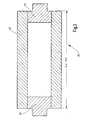
- FIG. 3 shows a longitudinal section through the rotating roller 22, which is formed in the illustrated embodiment of a sleeve 42 which is closed by a respective end pin 44. Close to these trunnions 44 the (in the FIG. 3 not shown) amplitude transformation pieces 24 at.
- FIG. 4 shows a side view of the rotating roller 22 with the laterally connected Amplungsentransformations republicen 24 and the radial bearings 26.
- the length 1 of the rotating roller 22 half lambda ( ⁇ / 2) imposed by the amplitude transformation pieces 24 oscillation of the rotating roller 22.
- Die two radial bearings 26 are quarter-wave ( ⁇ / 4) away from the end faces of the rotating roller 22 and the two amplitude transformation pieces 24 extended by lambda-quarter ( ⁇ / 4) on the radial bearings 26 addition.
- the graph shown by the reference numeral 46 shows the longitudinal vibration generated by the amplitude transformation pieces 24. Offset by lambda-quarter ( ⁇ / 4), the transverse oscillation 48, which causes a vibration of the rotating roller 22 in the radial direction, and with which the welding operation is carried out.
- the length 1 of the rotating rollers 22 half lambda ( ⁇ / 2), wherein the length 1 can also be a multiple thereof, as in FIG. 3 indicated. In this way the possibility is created Also to connect web 14 and 16 with each other, whose width is greater than lambda-half.
- the two rotating rollers 22 may be formed identically and are driven by the same frequency generator or oscillate in the same direction.
- FIG. 9 shows an embodiment in which the rotating roller 22 has a constriction E, whereby the diameter D over the length of the roller 22 is selectively reduced.
- FIGS. 10 to 12 show a further measure in which one of the two rotating rollers 22 is inclined, so that its longitudinal axis 52 is skewed to the longitudinal axis 54 of the platen 34.
- the helix angle is in FIG. 10 denoted by ⁇ .
- the in FIG. 11 marked with XII Clipping is in FIG. 12 shown enlarged and it is clearly visible that the line of contact of the two rollers is not parallel to the axis but obliquely. As a result, the contact pressure can be made uniform.
Landscapes
- Engineering & Computer Science (AREA)
- Mechanical Engineering (AREA)
- Lining Or Joining Of Plastics Or The Like (AREA)
- Pressure Welding/Diffusion-Bonding (AREA)
- Apparatuses For Generation Of Mechanical Vibrations (AREA)
- Treatment Of Fiber Materials (AREA)
- Rolls And Other Rotary Bodies (AREA)
- Processing And Handling Of Plastics And Other Materials For Molding In General (AREA)
- Coating Apparatus (AREA)
- Paper (AREA)
Description
- Die Erfindung betrifft eine Vorrichtung zum kontinuierlichen Verbinden und/oder Verfestigen von Materialbahnen mittels Ultraschall.
- Es ist bekannt, dass zum kontinuierlichen Verfestigen und/oder Verbinden von Materialbahnen diese zwischen einer rotierenden Walze und einer feststehenden oder ebenfalls rotierenden Sonotrode hindurchgeführt und dabei bearbeitet werden. Bei feststehenden Sonotroden können große Materialbreiten abgedeckt werden, jedoch entsteht zwischen der Sonotrode und der bewegten Materialbahn eine Reibkraft, die sich negativ auf das Schweißergebnis auswirkt. Außerdem bedingt die Reibkraft sowohl eine Erwärmung der Materialbahnen als auch eine Erwärmung der Sonotrode, wodurch der eingestellte Spalt verändert wird.
- Mit rotierenden Sonotroden kann zwar der oben beschriebene Nachteil der Reibung verhindert werden, jedoch sind nur geringe Schweißbreiten realisierbar. Aus der
US 2002/0130157 A1 ,US 5,707,483 und derUS 6,547,903 ist jeweils eine Sonotrode mit einer Breite bekannt, die kleiner als Lambda halbe ist. - Aus der
US 2002/0056589 A1 ist gemäß dem Oberbegriff des Anspruchs 1 eine rotierende Walze als Sonotrode bekannt, welche hülsenförmig ausgebildet ist und die Innenwand der Hülse im mittleren Bereich eine größere Dicke aufweist, als in den Randbereichen. Hierdurch soll eine über die Länge der Walze gleichmäßige radiale Schwingbewegung erreicht werden. DieDE 29 44 080 A1 offenbart eine walzenförmige Sonotrode, die mit Umfangsnuten versehen ist, so dass die zwischen den Nuten liegenden Rändelungen die Arbeitsflächen bilden. - Die
US 5,096,532 A1 zeigt eine walzenförmige Sonotrode, die mit Umfangsnuten oder mit Umfangswülsten versehen ist. - Der Erfindung liegt daher die Aufgabe zugrunde, eine Vorrichtung zum kontinuierlichen Verfestigen und/oder Verbinden von Materialbahnen bereit zu stellen, mit der auch breite Materialbahnen bearbeitet werden können.
- Diese Aufgabe wird mit einer Vorrichtung gelöst, die die Merkmale des Anspruchs 1 aufweist.
- Erfindungsgemäß ist der Außendurchmesser (D) der rotierenden Walze teilweise eingeschnürt, wobei insbesondere die Einschnürung (E) betragsmäßig einem Teil einer Lambda-halbe Welle der aufgezwungenen Schwingung entspricht (E = |x|·λ/2). Im schwingenden Zustand nimmt die rotierende Walze dann zeitweise die Zylinderform an, wodurch eine bessere Druckverteilung erreicht wird.
- Vorteilhaft ist die rotierende Walze im Außendurchmesser derart aufgedickt, dass sich eine gleichmäßige Anpresskraftverteilung über deren Länge ergibt. Diese Maßnahme trägt ebenfalls zu einer Vergleichmäßigung der Druckverteilung über die gesamte Walzenlänge bei, da die Verformung der Walze durch die Anpresskraft kompensiert wird. Insbesondere wird dies dadurch erreicht, dass die rotierende Walze eine Bombage aufweist. Die Durchmesseränderung der rotierenden Walze entspricht dabei exakt der Biegelinie.
- Bei der Vorrichtung besitzt die als rotierende Walze ausgebildete Sonotrode eine Länge, die Lambda-halbe entspricht oder einem Vielfachen von Lambda-halbe der aufgezwungenen Schwingung ist. Die Länge der rotierenden Walze hängt somit im Wesentlichen vom eingesetzten Material und der gewünschten Arbeitsfrequenz ab. Durch die Vervielfachung der Länge der rotierenden Walze auf ein Vielfaches von Lambda-halbe der Schwingung können auch sehr breite Materialbahnen bearbeitet werden, ohne dass hierfür mehrere einzelne Sonotroden verwendet werden müssten. Mit der erfindungsgemäßen Vorrichtung können die Materialbahnen auch getrocknet werden.
- Bei einer Weiterbildung ist vorgesehen, dass zwischen dem Amplitudentransformationsstück und der rotierenden Walze Radiallager vorgesehen sind. Diese Radiallager sind insbesondere in einem Schwingungsknoten der Longitudinalschwingung angeordnet, sodass keine oder vernachlässigbar geringe Schwingungsamplituden auf die Lager wirken.
- Mit Vorzug sind beidseits der rotierenden Walze ein Amplitudentransformationsstück und ein Ultraschallkonverter vorgesehen. Abhängig von der benötigten Energie, mit deren die Materialbahnen verfestigt oder miteinander verbunden werden sollen, kann entweder ein Konverter oder können zwei Konverter vorgesehen sein, wobei die Amplitudentransformationsstücke auswechselbar angeordnet, insbesondere eingeschraubt sind. Sie können aus dem gleichen Material bestehen, wie die rotierende Walze.
- Bei einem Ausführungsbeispiel sind die beiden Amplitudentransformationsstücke und die Walze in einem einzigen Bauteil vereint. Hierdurch werden höhere Festigkeiten erzeugt und es besteht keine Gefahr, dass sich die Amplitudentransformationsstücke von der Walze lösen.
- Mit Vorzug ist das Gegendruckwerkzeug eine rotierende Gegendruckwalze. Zwei gegenläufige Walzen bieten den Vorteil, dass die Reibung auf ein Minimum begrenzt wird und dass die Materialbahnen sehr schonend behandelt werden, ohne dass die Bearbeitung zu Formatänderungen führt.
- Eine Variante sieht vor, dass die Gegendruckwalze als aktive Walze ausgebildet ist und zwei Amplitudentransformationsstücke und wenigstens einen Konverter aufweist. Dabei besitzt jede Walze ihren eigenen Konverter.
- Dabei kann die Außenoberfläche entweder der rotierenden Walze oder der Gegendruckwalze glatt oder gemustert sein. Bei einer gemusterten Walze kann nun den Materialbahnen eine Struktur aufgeprägt werden, die zu einer noch innigeren Verbindung führt. Die Struktur kann eine Noppenstruktur, Waffelstruktur, Linienstruktur oder ein Fantasiemuster sein.
- Bei einem anderen Ausführungsbeispiel ist das Gegendruckwerkzeug feststehend und insbesondere als Messer, Klinge oder dergleichen ausgebildet. Dabei erstreckt sich das Messer, die Klinge oder dergleichen in tangentialer Richtung, sodass die Verfestigung oder Verbindung der Materialbahnen miteinander linienförmig erfolgt.
- Erfindungsgemäß ist die Spalthöhe zwischen der rotierenden Walze und dem Gegendruckwerkzeug einstellbar. Dabei kann die Einstellung geregelt sein, sodass die Spalthöhe konstant gehalten wird. Insbesondere bei Temperaturänderungen ist dies von Vorteil, da sich die Temperaturänderungen dann nicht in einer Änderung der Spalthöhe niederschlagen.
- Bei einer Weiterbildung ist vorgesehen, dass der von der rotierenden Walze auf die Materialbahn ausgeübte Druck einstellbar ist. Insbesondere kann auch eine Druckregelung vorgesehen sein, sodass die Materialbahnen stets mit gleichbleibendem Druck beaufschlagt werden.
- Eine bevorzugte Ausführungsform sieht vor, dass die rotierende Walze von einer Hülse mit jeweils einem Stirnzapfen gebildet wird. Eine derart ausgebildete Sonotrode ist zum einen leicht, zum anderen besitzt sie hervorragende Schwingungseigenschaften, da der Schwingungsbauch der Querschwingung bei einer Länge von Lambda-halbe in der Mitte der Hülse liegt.
- Vorteilhaft ist die rotierende Walze kühlbar oder heizbar. Hierdurch kann gezielt Wärme ausgetragen oder eingetragen werden, wodurch Schweißbedingungen konstant gehalten werden können.
- Bei einem bevorzugten Ausführungsbeispiel ist vorgesehen, dass am Gegendruckwerkzeug wenigstens zwei rotierende Walzen anliegen, die hintereinander geschaltet sind, wobei insbesondere die beiden hintereinandergeschalteten Walzen um einen Betrag (Δ1) in Achsrichtung zueinander versetzt sind. Hierdurch kann auf einfache Weise der Energieeintrag erhöht und die Verteilung der Energie verbessert werden. Mit Vorzug beträgt dabei der Betrag (Δ1) einer Lambda-viertel Welle der aufgezwungenen Schwingung (Δ1 = λ/4).
- Eine weitere Maßnahme zur Vergleichmäßigung der Druckverteilung ist, dass die Achse der rotierenden Walze und der Gegendruckwalze windschief zueinander stehen.
- Weiter Vorteile, Merkmale und Einzelheiten der Erfindung ergeben sich aus der nachfolgenden Beschreibung, in der unter Bezugnahme auf die Zeichnung besonders bevorzugte Ausführungsbeispiele im Einzelnen beschrieben sind. Dabei können die in der Zeichnung dargestellten und in den Ansprüchen sowie in der Beschreibung erwähnten Merkmale jeweils einzeln für sich oder in beliebiger Kombination erfindungswesentlich sein.
-
- Figur 1
- eine perspektivische Ansicht einer bevorzugten Ausführungsform der Erfindung mit als Gegendruckwalze ausgebildetem Gegendruckwerkzeug;
- Figur 2
- einen Schnitt II-II gemäß
Figur 1 ; - Figur 3
- einen Längsschnitt durch die rotierende Walze; und
- Figur 4
- eine Seitenansicht der Sonotrode mit Amplitudentransformationsstücken;
- Figur 5
- ein Schaubild, die in Querrichtung und in Längsrichtung verlaufenden Schwingungen zeigend;
- Figur 6
- eine perspektivische Ansicht einer Ausführungsform mit zwei rotierenden Walzen;
- Figur 7
- eine Seitenansicht in Richtung des Pfeils VII gemäß
Figur 6 ; - Figur 8
- eine Ausführungsform mit zwei versetzt zueinander angeordneten rotierenden Walzen;
- Figur 9
- eine Seitenansicht einer Ausführungsform mit einer Einschnürungen aufweisenden rotierenden Walze;
- Figur 10
- eine Draufsicht auf eine Ausführungsform, bei der die Achsen der rotierenden Walze und der Gegendruckwalze windschief zueinander stehen;
- Figur 11
- eine Seitenansicht in Richtung des Pfeils XI gemäß
Figur 10 ; und - Figur 12
- eine Vergrößerte Wiedergabe des Ausschnitts XII gemäß
Figur 11 . - In den
Figuren 1 und2 sind insgesamt mit 10 und 12 zwei rotierende Bauteile erkennbar, zwischen welchen zwei oder mehrere Materialbahnen 14 und 16 hindurchgeführt werden, wobei die beiden Materialbahnen 14 und 16 beim Durchtritt durch einen insgesamt mit 18 bezeichneten Arbeitsspalt miteinander verbunden und/oder verfestigt werden. Die Durchlaufrichtung ist mit dem Pfeil 20 angedeutet. - Das Bauteil 10 weist eine zentrale rotierende Walze 22 auf, an welche sich beidseits Amplitudentransformationsstücke 24 anschließen, an welchen Radiallager 26 vorgesehen sind. Die Amplitudentransformationsstücke 24 sind mit Ultraschallkonvertern 28 gekoppelt, über welche eine mechanische Schwingung in longitudinaler Richtung, das heißt in Richtung des Doppelpfeils 30 erzeugt werden. An den stirnseitigen Enden der Ultraschallkonverter 28 sind Drehkoppler 32 vorgesehen, über welche die Ultraschallkonverter 28 mit Spannung versorgt werden.
- Der rotierenden Walze 22 gegenüberliegend ist eine Gegendruckwalze 34 angeordnet, die ebenfalls über Radiallager 36 drehbar gelagert ist. Die Oberfläche der Gegendruckwalze 34 weist in Längsrichtung verlaufende Rippen 50 auf, die der Gegendruckwalze eine Struktur verleihen, die beim Verbinden der beiden Materialbahnen 14 und 16 auf diese übertragen wird.
- In der
Figur 2 sind mit den Pfeilen 38 und 40 die Drehrichtungen der rotierenden Walze 22 und der Gegendruckwalze 34 angedeutet. Außerdem ist der Drehkoppler 32 erkennbar, über welchen der Ultraschallkonverter 28 mit Spannung versorgt wird. - Die
Figur 3 zeigt einen Längsschnitt durch die rotierende Walze 22, die beim dargestellten Ausführungsbeispiel von einer Hülse 42 gebildet wird, welche von jeweils einem Stirnzapfen 44 verschlossen ist. An diesen Stirnzapfen 44 schließen sich die (in derFigur 3 nicht dargestellten) Amplitudentransformationsstücke 24 an. - Die
Figur 4 zeigt eine Seitenansicht der rotierenden Walze 22 mit den seitlich angeschlossenen Amplitudentransformationsstücken 24 sowie den Radiallagern 26. Beim dargestellten Ausführungsbeispiel entspricht die Länge 1 der rotierenden Walze 22 Lambda-halbe (λ/2) der durch die Amplitudentransformationsstücke 24 aufgezwungenen Schwingung der rotierenden Walze 22. Die beiden Radiallager 26 sind Lambda-viertel (λ/4) von den Stirnseiten der rotierenden Walze 22 entfernt und die beiden Amplitudentransformationsstücke 24 erstreckten sich um Lambda-viertel (λ/4) über die Radiallager 26 hinaus. - Das in
Figur 5 dargestellte Schaubild zeigt mit dem Bezugszeichen 46 die Longitudinalschwingung, die von den Amplitudentransformationsstücken 24 erzeugt wird. Um Lambda-viertel (λ/4) versetzt hierzu verläuft die Querschwingung 48, die eine Schwingung der rotierenden Walze 22 in radialer Richtung bewirkt, und mit der der Schweißvorgang durchgeführt wird. - Beim Ausführungsbeispiel der
Figur 4 beträgt die Länge 1 der rotierenden Walzen 22 Lambda-halbe (λ/2), wobei die Länge 1 auch ein vielfaches hiervon betragen kann, wie inFigur 3 angedeutet. Auf diese Weise wird die Möglichkeit geschaffen, auch Materialbahn 14 und 16 miteinander zu verbinden, deren Breite größer ist als Lambda-halbe. - In den
Figuren 6 bis 8 sind um die Gegendruckwalze 34 zwei rotierende Walzen 22 angeordnet, wobei die rotierenden Walzen 22 um einen Winkelversatz von 50° bis 60° hintereinander angeordnet und außerdem in axialer Richtung um einen Betrag von Δ1 = λ/4 zueinander versetzt sind, was sich deutlich ausFigur 8 ergibt. Die beiden rotierenden Walzen 22 können identisch ausgebildet sein und werden vom gleichen Frequenzgenerator angetrieben oder schwingen gleichsinnig. - Die
Figur 9 zeigt ein Ausführungsbeispiel, bei dem die rotierende Walze 22 eine Einschnürung E aufweist, wodurch der Durchmesser D über die Länge der Walze 22 gezielt reduziert wird. In derFigur 9 ist außerdem die Querschwingung 48 der Walze 22 schaubildlich dargestellt. Es ist erkennbar, dass die Einschnürung E immer dort am größten ist, wo sich ein Schwingungsbauch befindet. Die Einschnürung E ist also betragsmäßig das Produkt aus einer Konstanten und Lambda-halbe (E = |x|·λ/2). Wird die rotierende Walze 22 in Schwingung versetzt, dann nimmt sie zeitweise die Zylinderform an. - Die
Figuren 10 bis 12 zeigen eine weitere Maßnahme, bei der eine der beiden rotierenden Walzen 22 schräg gestellt ist, so dass deren Längsachse 52 windschief zur Längsachse 54 der Gegendruckwalze 34 steht. Der Schrägungswinkel ist inFigur 10 mit α bezeichnet. Der inFigur 11 mit XII gekennzeichnete Ausschnitt ist inFigur 12 vergrößert dargestellt und es ist deutlich erkennbar, dass die Berührungslinie der beiden Walzen nicht achsparallel sondern schräg verläuft. Dadurch kann der Anpressdruck vergleichmäßigt werden.
Claims (12)
- Vorrichtung zum kontinuierlichen Verbinden und/oder Verfestigen von Materialbahnen (14, 16) mittels Ultraschall mit einer als rotierende Walze (22) ausgebildeten Sonotrode, einem der rotierenden Walze (22) radial gegenüberliegenden Gegendruckwerkzeug, einem axial an die rotierende Walze (22) angesetzten Amplitudentransformationsstück (24), und einem sich an das Amplitudentransformationsstück (24) anschließenden Ultraschallkonverter (28) mit einer Spannungsversorgung, dadurch gekennzeichnet, dass der Außendurchmesser (D) der rotierenden Walze (22) zumindest teilweise eine Einschnürung (E) aufweist oder im Außendurchmesser derart aufgedickt ist, dass sich eine gleichmäßige Schweißkraftverteilung über deren Länge ergibt, wobei die Einschnürung (E) betragsmäßig einem Teil einer Lambda-halbe Welle der aufgezwungenen Schwingung entspricht (E = |x| · λ/2) und die rotierende Walse im Schwingenden Zustand zeitweise die Zylinderform annimmt.
- Vorrichtung nach Anspruch 1, dadurch gekennzeichnet, dass die Aufdickung von einer Bombage gebildet wird.
- Vorrichtung nach einem der vorhergehenden Ansprüche, dadurch gekennzeichnet, dass die Durchmesseränderung der rotierenden Walze (22) der Biegelinie entspricht.
- Vorrichtung nach einem der vorhergehenden Ansprüche, dadurch gekennzeichnet, dass die Länge (1) der rotierenden Walze (22) einer Lambda-halbe Welle der aufgezwungenen Schwingung oder einem Vielfachen davon entspricht wobei 1 = x · λ/2.
- Vorrichtung nach einem der vorhergehenden Ansprüche, dadurch gekennzeichnet, dass zwischen dem Amplitudentransformationsstück (24) und der rotierenden Walze (22) Radiallager (26) vorgesehen sind.
- Vorrichtung nach einem der vorhergehenden Ansprüche, dadurch gekennzeichnet, dass beidseits der rotierenden Walze (22) ein Amplitudentransformationsstück (24) und ein Ultraschallkonverter (28) vorgesehen sind.
- Vorrichtung nach einem der vorhergehenden Ansprüche, dadurch gekennzeichnet, dass die rotierende Walze (22) von einer Hülse (42) mit jeweils einem Stirnzapfen (44) gebildet wird.
- Vorrichtung nach einem der vorhergehenden Ansprüche, dadurch gekennzeichnet, dass das Gegendruckwerkzeug eine rotierende Gegendruckwalze (34) ist.
- Vorrichtung nach Anspruch 8, dadurch gekennzeichnet, dass die Achsen (52, 54) der rotierenden Walze (22) und der Gegendruckwalze (34) windschief zueinander stehen.
- Vorrichtung nach einem der vorhergehenden Ansprüche, dadurch gekennzeichnet, dass die Außenoberfläche der rotierenden Walze (22) und/oder Gegendruckwalze (34) glatt oder gemustert ist.
- Vorrichtung nach einem der vorhergehenden Ansprüche, dadurch gekennzeichnet, dass die Gegendruckwalze (34) als aktive Walze mit einem Amplitudentransformationsstück (24) und einem sich daran anschließenden Ultraschallkonverter (28) ausgebildet ist.
- Vorrichtung nach einem der Ansprüche 1 bis 7, dadurch gekennzeichnet, dass das Gegendruckwerkzeug feststehend ist und sich in tangentialer Richtung bezüglich der rotierenden Walze (22) erstreckt und insbesondere ein Messer, eine Klinge oder dergleichen ist.
Applications Claiming Priority (3)
| Application Number | Priority Date | Filing Date | Title |
|---|---|---|---|
| DE10337740 | 2003-08-13 | ||
| DE10343325A DE10343325A1 (de) | 2003-08-13 | 2003-09-11 | Vorrichtung zum kontinuierlichem Verbinden und/oder Verfestigen von Materialbahnen mittels Ultraschall |
| EP04400007A EP1514670B1 (de) | 2003-08-13 | 2004-02-20 | Vorrichtung zum kontinuierlichen Verbinden und/oder Verfestigen von Materialbahnen mittels Ultraschall |
Related Parent Applications (2)
| Application Number | Title | Priority Date | Filing Date |
|---|---|---|---|
| EP04400007A Division EP1514670B1 (de) | 2003-08-13 | 2004-02-20 | Vorrichtung zum kontinuierlichen Verbinden und/oder Verfestigen von Materialbahnen mittels Ultraschall |
| EP04400007.3 Division | 2004-02-20 |
Publications (3)
| Publication Number | Publication Date |
|---|---|
| EP1900499A2 EP1900499A2 (de) | 2008-03-19 |
| EP1900499A3 EP1900499A3 (de) | 2010-07-14 |
| EP1900499B1 true EP1900499B1 (de) | 2011-10-26 |
Family
ID=34137318
Family Applications (2)
| Application Number | Title | Priority Date | Filing Date |
|---|---|---|---|
| EP07021514A Expired - Lifetime EP1900499B1 (de) | 2003-08-13 | 2004-02-20 | Vorrichtung zum kontinuierlichen Verbinden und/oder Verfestigen von Materialbahnen mittels Ultraschall |
| EP04400007A Expired - Lifetime EP1514670B1 (de) | 2003-08-13 | 2004-02-20 | Vorrichtung zum kontinuierlichen Verbinden und/oder Verfestigen von Materialbahnen mittels Ultraschall |
Family Applications After (1)
| Application Number | Title | Priority Date | Filing Date |
|---|---|---|---|
| EP04400007A Expired - Lifetime EP1514670B1 (de) | 2003-08-13 | 2004-02-20 | Vorrichtung zum kontinuierlichen Verbinden und/oder Verfestigen von Materialbahnen mittels Ultraschall |
Country Status (4)
| Country | Link |
|---|---|
| US (1) | US7108764B2 (de) |
| EP (2) | EP1900499B1 (de) |
| AT (1) | ATE395180T1 (de) |
| DE (1) | DE502004007110D1 (de) |
Families Citing this family (20)
| Publication number | Priority date | Publication date | Assignee | Title |
|---|---|---|---|---|
| DE102009026952A1 (de) | 2009-06-16 | 2010-12-23 | Herrmann Ultraschalltechnik Gmbh & Co. Kg | Ultraschallbearbeitungsvorrichtung sowie Quersiegelsonotrode hierfür |
| DE102010013269A1 (de) | 2010-03-22 | 2011-09-22 | Andreas Knorr | Einseitige Wellpappenmaschine |
| DE102010041432A1 (de) * | 2010-09-27 | 2012-03-29 | Robert Bosch Gmbh | Ultraschallschwingeinheit |
| DE102011076712A1 (de) | 2011-05-30 | 2012-12-06 | Herrmann Ultraschalltechnik Gmbh & Co. Kg | Ultraschallschweißvorrichtung mit Drehkoppler |
| USD733776S1 (en) * | 2011-11-03 | 2015-07-07 | Telsonic Holding Ag | Sonotrode |
| US9854833B2 (en) | 2012-02-16 | 2018-01-02 | R. J. Reynolds Tobacco Company | Apparatus and associated method for forming a filter component of a smoking article |
| DE102013215106A1 (de) | 2013-08-01 | 2015-02-05 | PP-Tech GmbH | Sonotrodenwerkzeug mit integrierter Kühleinrichtung |
| DE102014100817A1 (de) * | 2014-01-24 | 2015-07-30 | Herrmann Ultraschalltechnik Gmbh & Co. Kg | Konvertereinheit |
| US11220081B2 (en) * | 2016-05-16 | 2022-01-11 | Cmd Corporation | Method and apparatus for pouch or bag making |
| EP3904057B1 (de) * | 2016-09-30 | 2023-05-24 | Dukane IAS, LLC | Vorrichtung und verfahren zur herstellung eines elastischen vliesstoffes |
| CN106744636A (zh) * | 2016-11-30 | 2017-05-31 | 宁波雄狮机械制造有限公司 | 一种面料导送及复合装置 |
| US10919106B2 (en) * | 2017-06-09 | 2021-02-16 | General Electric Company | Ultrasonic welding of annular components |
| CN107498174A (zh) * | 2017-10-17 | 2017-12-22 | 上海骄成机电设备有限公司 | 一种基于全波焊头的超声波滚动焊接装置 |
| IT201800003324A1 (it) | 2018-03-07 | 2019-09-07 | Gima Tt S P A | Procedimento per realizzare incarti ermetici e relativa macchina. |
| US11426992B2 (en) | 2018-10-04 | 2022-08-30 | Curt G. Joa, Inc. | Closed-loop adjustment system and method for gap control and leveling of ultrasonic devices |
| DE102021113875A1 (de) | 2021-05-28 | 2022-12-01 | Herrmann Ultraschalltechnik Gmbh & Co. Kg | Konvertereinheit mit mehreren Konverterelementen |
| DE102021113987A1 (de) | 2021-05-31 | 2022-12-01 | Herrmann Ultraschalltechnik Gmbh & Co. Kg | Ultraschallbearbeitungsvorrichtungen mit Abstützelement |
| US11872761B2 (en) * | 2021-08-12 | 2024-01-16 | Northrop Grumman Systems Corporation | Ultrasonic compaction device using reciprocating disk horns |
| US12543623B2 (en) * | 2023-05-04 | 2026-02-10 | Ball Horticultural Company | Systems and methods for producing seed pillows |
| US20240365700A1 (en) * | 2023-05-04 | 2024-11-07 | Ball Horticultural Company | Shrink-wrapped seed pillows |
Family Cites Families (24)
| Publication number | Priority date | Publication date | Assignee | Title |
|---|---|---|---|---|
| US2762295A (en) * | 1950-11-01 | 1956-09-11 | Carding Spec Canada | Distribution of pressure between a pair of pressure rollers |
| DE1425902C3 (de) * | 1964-01-22 | 1979-06-21 | Artos Dr.-Ing. Meier-Windhorst Kg, 2105 Seevetal | Rohrmantelwalze, insbesondere für Foulards |
| FR2440241A1 (fr) * | 1978-11-06 | 1980-05-30 | Mecasonic Sa | Dispositif pour souder par ultra-sons des feuilles metalliques |
| US4414045A (en) * | 1982-02-22 | 1983-11-08 | Burlington Industries, Inc. | High speed ultrasonic bonding |
| CH673128A5 (en) * | 1988-07-11 | 1990-02-15 | Escher Wyss Gmbh | Pliable roller paper press - has adjustable angle between roller axes to give variety of pressures without roller change |
| US5096532A (en) * | 1990-01-10 | 1992-03-17 | Kimberly-Clark Corporation | Ultrasonic rotary horn |
| US5552013A (en) * | 1994-06-29 | 1996-09-03 | Kimberly-Clark Corporation | Apparatus and method for rotary bonding |
| FR2743929B1 (fr) * | 1996-01-24 | 1998-04-10 | Aev Engineering Sarl | Dispositif pour la generation d'ondes ultrasonores |
| US5707483A (en) | 1996-07-05 | 1998-01-13 | Minnesota Mining And Manufacturing Company | Rotary acoustic horn |
| US5645681B1 (en) * | 1996-07-05 | 2000-03-14 | Minnesota Mining & Mfg | Stacked rotary acoustic horn |
| US5817199A (en) * | 1996-12-20 | 1998-10-06 | Kimberly-Clark Worldwide, Inc. | Methods and apparatus for a full width ultrasonic bonding device |
| US5976316A (en) | 1998-05-15 | 1999-11-02 | 3M Innovative Properties Company | Non-nodal mounting system for acoustic horn |
| US6099670A (en) | 1998-09-11 | 2000-08-08 | 3M Innovative Properties Company | Ultrasonic bonding method |
| US6059923A (en) | 1998-09-18 | 2000-05-09 | 3M Innovative Properties Company | Rotary acoustic horn with sleeve |
| DE10000231A1 (de) * | 2000-01-05 | 2001-07-19 | Schwaebische Huettenwerke Gmbh | Walzenanordnung und Walze |
| FR2809984B1 (fr) * | 2000-06-09 | 2006-07-14 | Aplix Sa | Sonotrode rotative permettant de souder en continu sur une grande largeur |
| US6877975B2 (en) * | 2000-10-17 | 2005-04-12 | David G. Wuchinich | Rolling pin horn |
| US6454890B1 (en) * | 2000-11-30 | 2002-09-24 | Kimberly-Clark Worldwide, Inc. | Method and apparatus for up to full width ultrasonic bonding |
| US6457626B1 (en) | 2001-01-29 | 2002-10-01 | Branson Ultrasonics Corporation | Symmetric ultrasonic rotary horn |
| DE20101860U1 (de) * | 2001-02-03 | 2002-06-13 | Eduard Küsters Maschinenfabrik GmbH & Co. KG, 47805 Krefeld | Kalander zum Behandeln einer Bahn |
| US6547903B1 (en) | 2001-12-18 | 2003-04-15 | Kimberly-Clark Worldwide, Inc. | Rotary ultrasonic bonder or processor capable of high speed intermittent processing |
| US7243894B2 (en) * | 2002-02-15 | 2007-07-17 | 3M Innovative Properties Company | Mount for vibratory elements |
| US6758925B1 (en) * | 2002-12-20 | 2004-07-06 | Kimberly-Clark Worldwide, Inc. | Acoustical energy transfer component |
| US6767420B2 (en) * | 2002-12-20 | 2004-07-27 | Kimberly-Clark Worldwide, Inc. | Ultrasonic horn with isotropic breathing characteristics |
-
2004
- 2004-02-20 EP EP07021514A patent/EP1900499B1/de not_active Expired - Lifetime
- 2004-02-20 DE DE502004007110T patent/DE502004007110D1/de not_active Expired - Lifetime
- 2004-02-20 AT AT04400007T patent/ATE395180T1/de active
- 2004-02-20 EP EP04400007A patent/EP1514670B1/de not_active Expired - Lifetime
- 2004-04-16 US US10/826,857 patent/US7108764B2/en not_active Expired - Lifetime
Also Published As
| Publication number | Publication date |
|---|---|
| US20050034820A1 (en) | 2005-02-17 |
| EP1900499A3 (de) | 2010-07-14 |
| DE502004007110D1 (de) | 2008-06-26 |
| US7108764B2 (en) | 2006-09-19 |
| EP1514670A2 (de) | 2005-03-16 |
| EP1900499A2 (de) | 2008-03-19 |
| ATE395180T1 (de) | 2008-05-15 |
| EP1514670A3 (de) | 2006-11-08 |
| EP1514670B1 (de) | 2008-05-14 |
Similar Documents
| Publication | Publication Date | Title |
|---|---|---|
| EP1900499B1 (de) | Vorrichtung zum kontinuierlichen Verbinden und/oder Verfestigen von Materialbahnen mittels Ultraschall | |
| EP2621710B1 (de) | Ultraschallschwingeinheit | |
| EP2288450B1 (de) | Sonotrode für eine ultraschallschwingeinheit | |
| EP2442964B1 (de) | Ultraschallbearbeitungsvorrichtung sowie quersiegelsonotrode hierfür | |
| DE69619406T2 (de) | Gestapeltes rotierendes akustisches horn | |
| DE69612021T2 (de) | Rotierendes akustisches horn | |
| DE102013100474A1 (de) | Ultraschallschweißvorrichtung mit schwingungsentkoppeltem Gegenwerkzeug | |
| EP1656231B1 (de) | Orbital-reibschweissverfahren und vorrichtung zur durchführung des verfahrens | |
| EP3102387B1 (de) | Ultraschallschweissvorrichtung mit vorwärmeinrichtung | |
| EP3507028B1 (de) | Ultraschallschwingsystem mit mantelflächen-amplitudentransformator | |
| EP2353737B1 (de) | Vorrichtung und Verfahren zur Ultraschall-Materialbearbeitung | |
| EP3317040B1 (de) | Vorrichtung zum verschweissen von bauteilen mittels ultraschalls durch torsionschwingungen | |
| DE1472357A1 (de) | Mit Torsionsschwingungsenergie arbeitende Vorrichtung | |
| EP1924346B1 (de) | Mischelement zum invertieren und mischen von strömenden stoffen in einem strömungskanal, sowie bausatz und mischer enthaltend dergestalte mischelemente | |
| EP0736356A1 (de) | Verfahren und Vorrichtung zum Verbinden einer Siegelfolie mit einer Materialbahn | |
| DE3218920A1 (de) | Anordnung zum ultraschall-schweissen | |
| DE1704178A1 (de) | Verfahren zum kontinuierlichen Nahtschweissen von Folien aus thermoplastischem Material mittels Ultraschall | |
| DE102008042419A1 (de) | Vorrichtung zum Erzeugen von hochfrequenten Schwingungen sowie Verfahren zu deren Betreiben | |
| DE102007053217B4 (de) | Haftverschlussteil | |
| EP1815966A2 (de) | Ultraschall-Verbindungsvorrichtung und Verfahren zum Verbinden von Materialbahnen | |
| EP4259419B1 (de) | Kompensation thermischer verformung an sonotroden | |
| EP4255720B1 (de) | Bearbeitungselement mit strukturelement | |
| DE102022126738A9 (de) | Ultraschallschwinger, Vorrichtung mit und Verwendung von einem Ultraschallschwinger sowie entsprechende Verfahren | |
| DE1203027B (de) | UEbertrager-Kopplungssystem fuer Schwingungsenergie | |
| HK1111128B (en) | Apparatus for continuously bonding and/or consolidating of web material by ultrasonics |
Legal Events
| Date | Code | Title | Description |
|---|---|---|---|
| PUAI | Public reference made under article 153(3) epc to a published international application that has entered the european phase |
Free format text: ORIGINAL CODE: 0009012 |
|
| AC | Divisional application: reference to earlier application |
Ref document number: 1514670 Country of ref document: EP Kind code of ref document: P |
|
| AK | Designated contracting states |
Kind code of ref document: A2 Designated state(s): AT BE BG CH CY CZ DE DK EE ES FI FR GB GR HU IE IT LI LU MC NL PT RO SE SI SK TR |
|
| AX | Request for extension of the european patent |
Extension state: LT LV |
|
| REG | Reference to a national code |
Ref country code: HK Ref legal event code: DE Ref document number: 1111128 Country of ref document: HK |
|
| RIC1 | Information provided on ipc code assigned before grant |
Ipc: B06B 3/00 20060101ALI20090424BHEP Ipc: B29C 65/08 20060101AFI20080102BHEP |
|
| PUAL | Search report despatched |
Free format text: ORIGINAL CODE: 0009013 |
|
| AK | Designated contracting states |
Kind code of ref document: A3 Designated state(s): AT BE BG CH CY CZ DE DK EE ES FI FR GB GR HU IE IT LI LU MC NL PT RO SE SI SK TR |
|
| AX | Request for extension of the european patent |
Extension state: LT LV |
|
| 17P | Request for examination filed |
Effective date: 20100729 |
|
| AKX | Designation fees paid |
Designated state(s): AT BE BG CH CY CZ DE DK EE ES FI FR GB GR HU IE IT LI LU MC NL PT RO SE SI SK TR |
|
| RIC1 | Information provided on ipc code assigned before grant |
Ipc: B06B 3/00 20060101ALI20110329BHEP Ipc: B29C 65/08 20060101AFI20110329BHEP |
|
| GRAP | Despatch of communication of intention to grant a patent |
Free format text: ORIGINAL CODE: EPIDOSNIGR1 |
|
| GRAS | Grant fee paid |
Free format text: ORIGINAL CODE: EPIDOSNIGR3 |
|
| GRAA | (expected) grant |
Free format text: ORIGINAL CODE: 0009210 |
|
| AC | Divisional application: reference to earlier application |
Ref document number: 1514670 Country of ref document: EP Kind code of ref document: P |
|
| AK | Designated contracting states |
Kind code of ref document: B1 Designated state(s): AT BE BG CH CY CZ DE DK EE ES FI FR GB GR HU IE IT LI LU MC NL PT RO SE SI SK TR |
|
| REG | Reference to a national code |
Ref country code: GB Ref legal event code: FG4D Free format text: NOT ENGLISH |
|
| REG | Reference to a national code |
Ref country code: CH Ref legal event code: EP |
|
| REG | Reference to a national code |
Ref country code: CH Ref legal event code: NV Representative=s name: MICHELI & CIE SA |
|
| REG | Reference to a national code |
Ref country code: IE Ref legal event code: FG4D |
|
| REG | Reference to a national code |
Ref country code: DE Ref legal event code: R096 Ref document number: 502004013012 Country of ref document: DE Effective date: 20111222 |
|
| REG | Reference to a national code |
Ref country code: NL Ref legal event code: VDEP Effective date: 20111026 |
|
| PG25 | Lapsed in a contracting state [announced via postgrant information from national office to epo] |
Ref country code: SE Free format text: LAPSE BECAUSE OF FAILURE TO SUBMIT A TRANSLATION OF THE DESCRIPTION OR TO PAY THE FEE WITHIN THE PRESCRIBED TIME-LIMIT Effective date: 20111026 Ref country code: GR Free format text: LAPSE BECAUSE OF FAILURE TO SUBMIT A TRANSLATION OF THE DESCRIPTION OR TO PAY THE FEE WITHIN THE PRESCRIBED TIME-LIMIT Effective date: 20120127 Ref country code: SI Free format text: LAPSE BECAUSE OF FAILURE TO SUBMIT A TRANSLATION OF THE DESCRIPTION OR TO PAY THE FEE WITHIN THE PRESCRIBED TIME-LIMIT Effective date: 20111026 Ref country code: NL Free format text: LAPSE BECAUSE OF FAILURE TO SUBMIT A TRANSLATION OF THE DESCRIPTION OR TO PAY THE FEE WITHIN THE PRESCRIBED TIME-LIMIT Effective date: 20111026 |
|
| REG | Reference to a national code |
Ref country code: IE Ref legal event code: FD4D |
|
| PG25 | Lapsed in a contracting state [announced via postgrant information from national office to epo] |
Ref country code: CY Free format text: LAPSE BECAUSE OF FAILURE TO SUBMIT A TRANSLATION OF THE DESCRIPTION OR TO PAY THE FEE WITHIN THE PRESCRIBED TIME-LIMIT Effective date: 20111026 |
|
| PG25 | Lapsed in a contracting state [announced via postgrant information from national office to epo] |
Ref country code: CZ Free format text: LAPSE BECAUSE OF FAILURE TO SUBMIT A TRANSLATION OF THE DESCRIPTION OR TO PAY THE FEE WITHIN THE PRESCRIBED TIME-LIMIT Effective date: 20111026 Ref country code: SK Free format text: LAPSE BECAUSE OF FAILURE TO SUBMIT A TRANSLATION OF THE DESCRIPTION OR TO PAY THE FEE WITHIN THE PRESCRIBED TIME-LIMIT Effective date: 20111026 Ref country code: BG Free format text: LAPSE BECAUSE OF FAILURE TO SUBMIT A TRANSLATION OF THE DESCRIPTION OR TO PAY THE FEE WITHIN THE PRESCRIBED TIME-LIMIT Effective date: 20120126 Ref country code: EE Free format text: LAPSE BECAUSE OF FAILURE TO SUBMIT A TRANSLATION OF THE DESCRIPTION OR TO PAY THE FEE WITHIN THE PRESCRIBED TIME-LIMIT Effective date: 20111026 Ref country code: IE Free format text: LAPSE BECAUSE OF FAILURE TO SUBMIT A TRANSLATION OF THE DESCRIPTION OR TO PAY THE FEE WITHIN THE PRESCRIBED TIME-LIMIT Effective date: 20111026 Ref country code: DK Free format text: LAPSE BECAUSE OF FAILURE TO SUBMIT A TRANSLATION OF THE DESCRIPTION OR TO PAY THE FEE WITHIN THE PRESCRIBED TIME-LIMIT Effective date: 20111026 |
|
| BERE | Be: lapsed |
Owner name: HERRMANN ULTRASCHALLTECHNIK G.M.B.H. & CO. KG Effective date: 20120228 |
|
| PG25 | Lapsed in a contracting state [announced via postgrant information from national office to epo] |
Ref country code: RO Free format text: LAPSE BECAUSE OF FAILURE TO SUBMIT A TRANSLATION OF THE DESCRIPTION OR TO PAY THE FEE WITHIN THE PRESCRIBED TIME-LIMIT Effective date: 20111026 |
|
| PLBE | No opposition filed within time limit |
Free format text: ORIGINAL CODE: 0009261 |
|
| STAA | Information on the status of an ep patent application or granted ep patent |
Free format text: STATUS: NO OPPOSITION FILED WITHIN TIME LIMIT |
|
| PG25 | Lapsed in a contracting state [announced via postgrant information from national office to epo] |
Ref country code: MC Free format text: LAPSE BECAUSE OF NON-PAYMENT OF DUE FEES Effective date: 20120229 |
|
| REG | Reference to a national code |
Ref country code: HK Ref legal event code: GR Ref document number: 1111128 Country of ref document: HK |
|
| 26N | No opposition filed |
Effective date: 20120727 |
|
| REG | Reference to a national code |
Ref country code: DE Ref legal event code: R097 Ref document number: 502004013012 Country of ref document: DE Effective date: 20120727 |
|
| PG25 | Lapsed in a contracting state [announced via postgrant information from national office to epo] |
Ref country code: BE Free format text: LAPSE BECAUSE OF NON-PAYMENT OF DUE FEES Effective date: 20120228 |
|
| REG | Reference to a national code |
Ref country code: AT Ref legal event code: MM01 Ref document number: 530330 Country of ref document: AT Kind code of ref document: T Effective date: 20120220 |
|
| PG25 | Lapsed in a contracting state [announced via postgrant information from national office to epo] |
Ref country code: ES Free format text: LAPSE BECAUSE OF FAILURE TO SUBMIT A TRANSLATION OF THE DESCRIPTION OR TO PAY THE FEE WITHIN THE PRESCRIBED TIME-LIMIT Effective date: 20120206 |
|
| PG25 | Lapsed in a contracting state [announced via postgrant information from national office to epo] |
Ref country code: AT Free format text: LAPSE BECAUSE OF NON-PAYMENT OF DUE FEES Effective date: 20120220 Ref country code: FI Free format text: LAPSE BECAUSE OF FAILURE TO SUBMIT A TRANSLATION OF THE DESCRIPTION OR TO PAY THE FEE WITHIN THE PRESCRIBED TIME-LIMIT Effective date: 20111026 |
|
| PG25 | Lapsed in a contracting state [announced via postgrant information from national office to epo] |
Ref country code: TR Free format text: LAPSE BECAUSE OF FAILURE TO SUBMIT A TRANSLATION OF THE DESCRIPTION OR TO PAY THE FEE WITHIN THE PRESCRIBED TIME-LIMIT Effective date: 20111026 |
|
| PG25 | Lapsed in a contracting state [announced via postgrant information from national office to epo] |
Ref country code: LU Free format text: LAPSE BECAUSE OF NON-PAYMENT OF DUE FEES Effective date: 20120220 |
|
| PG25 | Lapsed in a contracting state [announced via postgrant information from national office to epo] |
Ref country code: PT Free format text: LAPSE BECAUSE OF FAILURE TO SUBMIT A TRANSLATION OF THE DESCRIPTION OR TO PAY THE FEE WITHIN THE PRESCRIBED TIME-LIMIT Effective date: 20111026 Ref country code: HU Free format text: LAPSE BECAUSE OF FAILURE TO SUBMIT A TRANSLATION OF THE DESCRIPTION OR TO PAY THE FEE WITHIN THE PRESCRIBED TIME-LIMIT Effective date: 20040220 |
|
| REG | Reference to a national code |
Ref country code: FR Ref legal event code: PLFP Year of fee payment: 13 |
|
| REG | Reference to a national code |
Ref country code: FR Ref legal event code: PLFP Year of fee payment: 14 |
|
| REG | Reference to a national code |
Ref country code: FR Ref legal event code: PLFP Year of fee payment: 15 |
|
| PGFP | Annual fee paid to national office [announced via postgrant information from national office to epo] |
Ref country code: FR Payment date: 20230217 Year of fee payment: 20 Ref country code: CH Payment date: 20230307 Year of fee payment: 20 |
|
| PGFP | Annual fee paid to national office [announced via postgrant information from national office to epo] |
Ref country code: IT Payment date: 20230228 Year of fee payment: 20 Ref country code: GB Payment date: 20230215 Year of fee payment: 20 |
|
| PGFP | Annual fee paid to national office [announced via postgrant information from national office to epo] |
Ref country code: DE Payment date: 20230412 Year of fee payment: 20 |
|
| REG | Reference to a national code |
Ref country code: DE Ref legal event code: R071 Ref document number: 502004013012 Country of ref document: DE |
|
| REG | Reference to a national code |
Ref country code: CH Ref legal event code: PL |
|
| REG | Reference to a national code |
Ref country code: GB Ref legal event code: PE20 Expiry date: 20240219 |
|
| PG25 | Lapsed in a contracting state [announced via postgrant information from national office to epo] |
Ref country code: GB Free format text: LAPSE BECAUSE OF EXPIRATION OF PROTECTION Effective date: 20240219 |