EP1900519B1 - Machine d'impression - Google Patents
Machine d'impression Download PDFInfo
- Publication number
- EP1900519B1 EP1900519B1 EP07115695.4A EP07115695A EP1900519B1 EP 1900519 B1 EP1900519 B1 EP 1900519B1 EP 07115695 A EP07115695 A EP 07115695A EP 1900519 B1 EP1900519 B1 EP 1900519B1
- Authority
- EP
- European Patent Office
- Prior art keywords
- printing
- machine
- rock
- printing press
- supporting
- Prior art date
- Legal status (The legal status is an assumption and is not a legal conclusion. Google has not performed a legal analysis and makes no representation as to the accuracy of the status listed.)
- Not-in-force
Links
- 238000007639 printing Methods 0.000 title claims description 175
- 239000011435 rock Substances 0.000 claims description 18
- 239000010438 granite Substances 0.000 claims description 13
- 241000282813 Aepyceros melampus Species 0.000 claims description 5
- 239000004579 marble Substances 0.000 claims description 2
- 230000001447 compensatory effect Effects 0.000 claims 1
- 230000005484 gravity Effects 0.000 claims 1
- 239000004575 stone Substances 0.000 description 40
- 239000000463 material Substances 0.000 description 14
- 238000000034 method Methods 0.000 description 14
- 238000012545 processing Methods 0.000 description 13
- 239000007769 metal material Substances 0.000 description 11
- 238000010276 construction Methods 0.000 description 8
- 238000004519 manufacturing process Methods 0.000 description 8
- 239000000758 substrate Substances 0.000 description 7
- 229910052500 inorganic mineral Inorganic materials 0.000 description 6
- 239000011707 mineral Substances 0.000 description 6
- 238000007645 offset printing Methods 0.000 description 6
- 239000002969 artificial stone Substances 0.000 description 5
- 239000004567 concrete Substances 0.000 description 5
- 238000004804 winding Methods 0.000 description 5
- 239000011888 foil Substances 0.000 description 4
- 238000005266 casting Methods 0.000 description 3
- 238000005516 engineering process Methods 0.000 description 3
- 238000000926 separation method Methods 0.000 description 3
- 229910000831 Steel Inorganic materials 0.000 description 2
- 239000000853 adhesive Substances 0.000 description 2
- 238000005520 cutting process Methods 0.000 description 2
- 238000011161 development Methods 0.000 description 2
- 230000018109 developmental process Effects 0.000 description 2
- 238000007646 gravure printing Methods 0.000 description 2
- 239000004922 lacquer Substances 0.000 description 2
- 238000003754 machining Methods 0.000 description 2
- 229910052751 metal Inorganic materials 0.000 description 2
- 239000002184 metal Substances 0.000 description 2
- 239000002986 polymer concrete Substances 0.000 description 2
- 239000011150 reinforced concrete Substances 0.000 description 2
- 238000007650 screen-printing Methods 0.000 description 2
- 239000007787 solid Substances 0.000 description 2
- 238000007711 solidification Methods 0.000 description 2
- 230000008023 solidification Effects 0.000 description 2
- 239000010959 steel Substances 0.000 description 2
- 229910001018 Cast iron Inorganic materials 0.000 description 1
- 229910001208 Crucible steel Inorganic materials 0.000 description 1
- 235000019738 Limestone Nutrition 0.000 description 1
- RTAQQCXQSZGOHL-UHFFFAOYSA-N Titanium Chemical compound [Ti] RTAQQCXQSZGOHL-UHFFFAOYSA-N 0.000 description 1
- 230000001070 adhesive effect Effects 0.000 description 1
- 229910052782 aluminium Inorganic materials 0.000 description 1
- XAGFODPZIPBFFR-UHFFFAOYSA-N aluminium Chemical compound [Al] XAGFODPZIPBFFR-UHFFFAOYSA-N 0.000 description 1
- 239000000969 carrier Substances 0.000 description 1
- 238000006243 chemical reaction Methods 0.000 description 1
- 238000000576 coating method Methods 0.000 description 1
- 238000005260 corrosion Methods 0.000 description 1
- 230000007797 corrosion Effects 0.000 description 1
- 238000013016 damping Methods 0.000 description 1
- 230000001419 dependent effect Effects 0.000 description 1
- 238000001035 drying Methods 0.000 description 1
- 230000000694 effects Effects 0.000 description 1
- 238000004049 embossing Methods 0.000 description 1
- 239000006028 limestone Substances 0.000 description 1
- 239000007788 liquid Substances 0.000 description 1
- 238000005259 measurement Methods 0.000 description 1
- 150000002739 metals Chemical class 0.000 description 1
- 239000000615 nonconductor Substances 0.000 description 1
- 239000003973 paint Substances 0.000 description 1
- 230000000704 physical effect Effects 0.000 description 1
- 238000004080 punching Methods 0.000 description 1
- 238000012360 testing method Methods 0.000 description 1
- 239000010936 titanium Substances 0.000 description 1
- 229910052719 titanium Inorganic materials 0.000 description 1
- 230000009466 transformation Effects 0.000 description 1
- 238000011144 upstream manufacturing Methods 0.000 description 1
Images




Classifications
-
- B—PERFORMING OPERATIONS; TRANSPORTING
- B41—PRINTING; LINING MACHINES; TYPEWRITERS; STAMPS
- B41F—PRINTING MACHINES OR PRESSES
- B41F13/00—Common details of rotary presses or machines
- B41F13/0024—Frames
-
- B—PERFORMING OPERATIONS; TRANSPORTING
- B41—PRINTING; LINING MACHINES; TYPEWRITERS; STAMPS
- B41F—PRINTING MACHINES OR PRESSES
- B41F13/00—Common details of rotary presses or machines
-
- B—PERFORMING OPERATIONS; TRANSPORTING
- B41—PRINTING; LINING MACHINES; TYPEWRITERS; STAMPS
- B41F—PRINTING MACHINES OR PRESSES
- B41F5/00—Rotary letterpress machines
-
- B—PERFORMING OPERATIONS; TRANSPORTING
- B41—PRINTING; LINING MACHINES; TYPEWRITERS; STAMPS
- B41P—INDEXING SCHEME RELATING TO PRINTING, LINING MACHINES, TYPEWRITERS, AND TO STAMPS
- B41P2217/00—Printing machines of special types or for particular purposes
- B41P2217/10—Printing machines of special types or for particular purposes characterised by their constructional features
- B41P2217/11—Machines with modular units, i.e. with units exchangeable as a whole
Definitions
- the invention relates to a printing press, in particular for the printing of labels, comprising a machine support structure comprising a support element and at least one printing unit, of which at least one part is received in the support element by means of a bearing element.
- WO 2005/028202 A1 A large and commercially very important field of application of modern printing technology is the production of labels.
- WO 2005/028202 A1 is a label printing machine with individual drives for individual printing units in series construction described in which a substrate web is processed into multicolored and possibly with special effects finished labels.
- the printing process used in the label printing machine can be flexibly converted according to the order of the job in order to change the format or the other to carry out a process change so that different product requirements can be met.
- the label printing machine has a plurality of separating points, on which releasably connectable printing units or printing unit parts of different printing methods, in particular flexographic printing, gravure printing, offset printing and screen printing, can be recorded.
- the DE 94 20 690 U1 shows a web-fed rotary press with portal carriers made of reinforced ready-mixed concrete. This shows also the EP 0 020 886 A1 .
- the DE 43 17 684 A1 discloses a printing press whose foundation - as is common practice - consists of concrete. Furthermore come in the substructure of the printing machine side members made of reinforced concrete used. According to the EP 1 500 500 A1 It is known to manufacture the framework, which forms the machine frame of a printing press, from polymer concrete or mineral casting.
- the EP 0 738 590 A1 describes that the substructure of a printing press forming support elements made of steel, cast iron, reinforced concrete or polymer concrete can be produced.
- the object of the present invention is to provide a stable printing machine in which negative consequences resulting from undesirable properties of metallic materials are reduced or avoided.
- a printing press according to the invention in particular for the printing and / or the production of labels, has a machine support construction which comprises at least one comprises support made of stone, and at least one printing unit, of which at least one part is received in the support element by means of a bearing element.
- stone is understood to mean a solid mineral mass or a single object consisting of such a material.
- Stone is natural stone. Natural stone is a solid, during the course of Earth's history, a mineral mass, a part of the inorganic components of the earth's crust or a single, consisting of this material object. Natural stone can be formed by solidification of molten minerals (basalt, granite, volcanic rocks) or by Solidification of loose material (sandstone, limestone). On the other hand, artificial stones are available through technical processes.
- the support element is made of stone, in particular of one or more stones, preferably entirely made of stone.
- large parts of the machine support structure or the entire machine support structure may be made of stone.
- the entire printing unit is accommodated in the support element.
- the bearing element may be releasably or non-detachably connected to the support element.
- the bearing element may in particular be a bush or a pivot bearing or a pivot bearing or a grooved rail made of a metallic material.
- the bearing element may be fixed to the stone support element by an adhesive connection or by a screw connection, in particular glued or screwed be.
- the bearing element may also be an insert in the support element.
- the bearing element may be part of the printing unit or part of the machine support structure.
- the part of the printing unit may be a component of the printing unit, in particular a shaft, or an assembly of the printing unit.
- the printing unit can serve for the application of ink, lacquer, clear lacquer or a substrate, such as a foil, a hologram or an RFID circuit, on a printing substrate.
- a printing unit may in particular comprise an inking unit and / or a dampening unit. It can be added directly without bearing element or indirectly by means of a bearing element more parts of the printing press in the support element.
- control components and / or drive components and / or processing devices such as in particular dryers and cutters, be attached to the support element.
- the supporting structure can also be referred to as a superstructure, machine construction or supporting structure.
- the printing machine is preferably a rotary printing machine.
- the machine support structure in particular the support element, is part of the printing machine and not part of the environment in which the printing press is placed.
- the support element can not be seen separately or independently of the printing press.
- the support element is not a support structure, a substructure, a Support element, a hall floor, a pressroom foundation, a floor slab or a false ceiling for a printing press.
- the one or more printing units are received in the support member, not as part of a printing press on the support member.
- a dimensionally stable printing machine is created under varying thermal conditions. Stones have a significantly lower thermal expansion coefficient than metals. Also with respect to mechanical forces, the support element of the printing press according to the invention is particularly dimensionally stable and in particular more rigid or more stable than commonly used metallic materials. In addition, stone has a stronger vibration damping than the commonly used metallic materials. Finally, stone is an electrical insulator, so that consequently no corrosion occurs. The material stone can be machined very precisely, so that a qualitatively very high accuracy of the geometry of the support element can be achieved.
- the stone support element can apply the necessary for the positioning of the at least one part of the printing unit in space bearing forces and / or a compensating force acting on the part gravitational force to the main part or whole.
- the support element is primarily used to build or fix the printing unit of the printing press according to the invention.
- a plurality of printing units can be accommodated in the support element.
- the machine support structure may include a plurality of support members made of stone.
- the one or more support members are made according to the invention of a monoblock or a monolith.
- the monoblock also referred to as a single block
- the monoblock is used to accommodate all printing units in series, in particular in the horizontal direction.
- table blocks and / or traverses can be dispensed with, so that a cost advantage, in particular during production, and a simplified transport result.
- the monoblock can rest on separate feet, base profiles or the like.
- the stone-made support element of the printing press may be a base frame, a machine frame, a machine foundation, a base plate, a base unit, a printing unit frame, a printing unit lower part, a side wall, a side wall, a side frame, a support wall, a portal support or a connection profile.
- the stone is a natural stone.
- the support element is made of a naturally occurring stone.
- the natural stone may be a igneous rock, a plutonic rock, a gangue, an effusion rock or a transformation rock.
- the natural stone is preferably a granite, a granitic rock, a granite porphyry Gneiss or a marble.
- the natural stone is a black granite, a gabbro or an impala granite.
- Impala granite is particularly preferred.
- the expansion coefficient of Impala granite is only about 0.2 times that of cast steel.
- the printing machine according to the invention can be a web-processing printing press, in particular for label printing.
- the web-processing printing machine can have a winding for the printed substrate web.
- the printing press can be a narrow web press.
- the printing material web may be below 550 mm wide, in particular below 340 mm, even below 285 mm.
- the printing press according to the invention may be a sheet-fed printing press.
- a sheet-fed printing machine having a feeder, a plurality of printing units (typically 4, 6, 8, 10 or 12 printing units, in particular offset printing units) and a boom.
- the sheet-processing printing press can be a perfecting press (reversing machine).
- the printing press is a label printing machine.
- the printing machine may be suitable for the production of self-adhesive labels.
- the label printing machine can have individual features and feature combinations, as described in the document WO 2005/028202 A1 are disclosed.
- the printing machine can be an offset printing machine or at least one offset printing unit, also with several other printing units that work according to other printing methods (hybrid printing press).
- a preferred embodiment of the printing machine according to the invention in particular a label printing machine, has a plurality of printing units which (partially or all of them) operate according to different printing methods from one another.
- the various printing methods may include one or more of the following printing methods: flexographic, gravure, letterpress, letterpress, direct or indirect lithographic, lithographic, offset, waterless offset, cold foil stamping, hot foil stamping, inkjet, liquid toner, screen, xerographic.
- the printing machine in particular label printing machine, can be converted between different printing methods, by partially or completely printing unit of a first printing process of a separation point with the rest of the printing press - and possibly also the remainder of the Printing unit - removed and partially or completely replaced by a recorded at the separation point printing unit of a second printing process.
- the printing machine according to the invention may have the features mentioned individually or in combination.
- the printing machine according to the invention can furthermore or alternatively have the following features individually or in combinations:
- the printing length and / or the printing width of the printing press can be variable.
- the printing press may have a modular construction for a plurality of printing units.
- Each of the plurality of printing units of the printing press according to the invention may have a supporting structure with at least one supporting element made of stone.
- the printing units of the printing press according to the invention can be arranged in a row construction essentially in the horizontal direction.
- the printing units can be driven separately by individual drives.
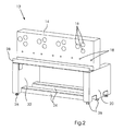
- the FIG. 1 shows a machine support structure 12 of stone support elements of a preferred embodiment of a printing machine 10 according to the invention (see FIG. 5 ) in a view from the operating side.
- This embodiment belongs to the first group of embodiments in which natural stone is used.
- the machine support structure 12 has a support member 14 made of stone, also referred to as a gantry support, which serves to receive printing units (here by way of example four, for standard four-color printing) and further components, in particular web guide rollers.
- the support element 14 has a number of shaft bores 16 each arranged in groups for the individual printing units, and furthermore roller bores 18.
- the printing units 30 are arranged horizontally in a row construction.
- the main components of the frame of the machine support structure 12 on which the support member 14 rests is made of stone in this embodiment.
- the frame comprises a left side cheek 20, a right side cheek 22 and two connecting profiles 24.
- the stone Impala granite is used.
- the machine support structure 12 rests on adjustable feet 26.
- a cable bridge 28 can be seen behind the support member 14, which simultaneously represents another connection profile of the machine support structure 12.
- FIG. 12 is a view from the drive side of the embodiment of the machine support structure 12 according to FIG. 1 , On the support member 14 are from this page separate drive units for each of the printing units 30 (see FIG. 5 ) attached.
- the rotatably mounted drive shafts of the printing units 30 then pass through the shaft bores 16 in which they are received by means of bearing elements (in this case roller bearings).
- bearing elements in this case roller bearings.
- the left side cheek 20, the right side cheek 22, the connecting profiles 24, the adjustable feet 26 and the cable bridge 28 can also be seen.
- the rollers for web guide rotatably received in the roller bores 18 are not driven.
- FIG. 3 is an illustration of the embodiment of the printing machine 10 according to the invention FIG. 1 from the.
- the support element 14 with the shaft bores 16 and roller bores 18 is connected, inter alia, by means of angle pieces 32 with the left and right side cheek 20,22. With the connection profiles 24 a stable frame of the machine support structure 12 is formed.
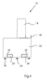
- FIG. 4 the machine support structure 12 of the printing machine 10 according to the invention is shown in a view from the right side.
- the support member 14 and the right side cheek 22, which rests on adjustable feet 26 can be seen.
- the connection profiles 24 are received in recesses 34 of the right side cheek 22.
- the cable bridge 28 has a U-shaped profile.
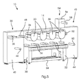
- FIG. 5 shows a preferred embodiment of a printing press 10 according to the invention with a machine support structure 12 according to the FIG. 1 ,
- This embodiment is a web-processing printing machine, a label printing machine.
- the stone elements and components of a label printing machine are preferably made of natural stone, in particular granite.
- the machine support structure 12 with the already using the FIGS. 1 to 4 explained components support member 14, left side cheek 20, right side cheek 22 and connecting profiles 24 forms a support for a processing part or printing part of the printing machine 10, in which a not shown here printing material (a substrate), the path of which runs over web guide rollers 36 through the machine processed becomes.
- the processing part comprises four printing units 30, which are accommodated on the support element 14.
- the printing units 30 of the embodiment shown are on the one hand format variable, in particular variable printing lengths can be generated by using cylinders of different circumferential lengths, on the other hand can be converted between different printing methods. In particular, between Flexographic and gravure printing can be changed by simply modifying components of the printing units. Even screen printing can be used by simple conversion.
- a printing unit 30 can also be completely replaced by a stamping plant or a stamping plant, in particular a hot foil stamping machine. The punching or embossing is then by the in relation to the FIG. 2 already mentioned separate drive the replaced printing unit 30 operated.
- a machine inlet part 38 Upstream of the machining part is a machine inlet part 38, which has a first, made of stone support wall 40. Downstream of the processing part is a machine outlet part 42, which has a second, made of stone support wall 44.
- An essential functionality of the machine entry part 38 is the processing of a printing material web to be printed on a roll.
- a processing device 46 is provided.
- the machine inlet part 38 comprises a discharge device 48.
- the machine outlet part 42 comprises a winding device 50 for the processed (in particular printed) printing material web on a roll.
- the printing machine has a cutting device 52, are separated in the nip of the remaining on the carrier web of the substrate labels of the web of the lattice-shaped cut remnants.
- This web of cut remnants is wound on a reel in a rewind unit 54 which has a support wall 56 made of stone and a winding shaft 58.
- FIG. 6 is the one in the FIG. 5 shown preferred embodiment of the printing machine 10, the label printing machine with support elements made of natural stone, from to see.
- the label printing machine with support elements made of natural stone from to see.
- FIG. 7 schematically shows a view of an alternative embodiment of a printing machine 10 according to the invention.
- a printing machine 10 is a sheet-fed offset printing machine for four-color printing in a row construction.
- the Printing machine is modular and includes a feeder 60, four printing units 30 and a boom 62. Arches are separated from a feeder stack 64 fed to the printing machine 10 for processing and stored after drying in the boom on a delivery stack 66.
- the side walls 68 of the printing units 30 and corresponding components of the support structure of the printing units 30 are manufactured as support elements 14 in stone.
- devices for mechanical compensation adjustment of components of the printing unit are provided in the printing press according to the invention, here the embodiment of a sheet-processing offset printing machine, so that the precisely desired position of the components to each other in function of temperature is reached automatically.
Landscapes
- Engineering & Computer Science (AREA)
- Mechanical Engineering (AREA)
- Rotary Presses (AREA)
- Coloring (AREA)
- Support Of The Bearing (AREA)
- Accessory Devices And Overall Control Thereof (AREA)
- Printing Methods (AREA)
- Press-Shaping Or Shaping Using Conveyers (AREA)
Claims (9)
- Machine d'impression (10) présentant une construction support (12), qui comprend un élément porteur (14) et au moins un groupe d'impression (30) dont au moins une partie est logée dans l'élément porteur (14) au moyen d'un élément de palier,
caractérisée en ce que
la construction support (12) présente un grand nombre d'éléments porteurs (14), un élément porteur respectif étant fabriqué à partir d'un monobloc en pierre naturelle. - Machine d'impression (10) selon la revendication 1,
caractérisée en ce que la pierre naturelle est une pierre ignée, une roche de profondeur, une roche effusive ou une roche métamorphique. - Machine d'impression (10) selon la revendication 1,
caractérisée en ce que la pierre naturelle est un granit, une roche granitique, un porphyre granitique, un gneiss ou un marbre. - Machine d'impression (10) selon la revendication 1,
caractérisée en ce que la pierre naturelle est un granit noir ou un granit impala. - Machine d'impression selon l'une des revendications précédentes, caractérisée en ce que l'élément porteur pierreux (14) apporte les forces de logement nécessaires au positionnement d'au moins une partie du groupe d'impression (30) dans la salle et/ou une force de gravitation agissant sur la partie.
- Machine d'impression selon l'une des revendications précédentes, caractérisée en ce qu'un grand nombre de groupes d'impression entiers (30) sont logés dans l'élément porteur (14).
- Machine d'impression selon l'une des revendications précédentes, caractérisée en ce qu'un groupe d'impression respectif (30) est logé sur un côté dans l'élément porteur (14).
- Machine d'impression selon l'une des revendications précédentes, caractérisée en ce que l'élément porteur (14) est un bâti, un cadre de machine, une fondation de machine, une plaque de base, une unité de base, un cadre de groupe d'impression, une partie inférieure de groupe d'impression, une joue latérale (20, 22), une paroi latérale (68) un cadre latérale, une paroi porteuse (40, 44), un portique ou un profilé de connexion (24).
- Machine d'impression (10) selon la revendication 1, caractérisée en ce qu'un grand nombre de groupes d'impression entier sont logés sur un côté dans l'élément porteur (14).
Applications Claiming Priority (1)
| Application Number | Priority Date | Filing Date | Title |
|---|---|---|---|
| DE102006042884A DE102006042884A1 (de) | 2006-09-13 | 2006-09-13 | Druckmaschine |
Publications (3)
| Publication Number | Publication Date |
|---|---|
| EP1900519A2 EP1900519A2 (fr) | 2008-03-19 |
| EP1900519A3 EP1900519A3 (fr) | 2011-09-07 |
| EP1900519B1 true EP1900519B1 (fr) | 2013-04-24 |
Family
ID=38922688
Family Applications (1)
| Application Number | Title | Priority Date | Filing Date |
|---|---|---|---|
| EP07115695.4A Not-in-force EP1900519B1 (fr) | 2006-09-13 | 2007-09-05 | Machine d'impression |
Country Status (7)
| Country | Link |
|---|---|
| US (1) | US7980176B2 (fr) |
| EP (1) | EP1900519B1 (fr) |
| JP (1) | JP2008068624A (fr) |
| CN (1) | CN101143506B (fr) |
| DE (1) | DE102006042884A1 (fr) |
| DK (1) | DK1900519T3 (fr) |
| ES (1) | ES2412008T3 (fr) |
Families Citing this family (8)
| Publication number | Priority date | Publication date | Assignee | Title |
|---|---|---|---|---|
| DE112008002084T5 (de) * | 2007-07-31 | 2010-08-26 | Song, Byung Jun, Anyang | Vorrichtung zum Zuführen einer Folie einer Druckmaschine mit Spannung |
| DE102007045876A1 (de) | 2007-09-25 | 2009-04-09 | Gallus Druckmaschinen Gmbh | Druckwerk und Druckmaschine |
| DE102008013315A1 (de) | 2008-03-10 | 2009-09-17 | Gallus Druckmaschinen Gmbh | Druckwerk und Druckmaschine |
| JP5293518B2 (ja) * | 2009-09-10 | 2013-09-18 | 株式会社リコー | 画像形成装置及びその組み立て方法 |
| DE102012003157A1 (de) * | 2012-02-16 | 2013-08-22 | Gallus Druckmaschinen Gmbh | Trägereinheit und Bearbeitungsmodul zum Aufbau einer Druckmaschine |
| US10452660B2 (en) * | 2013-05-31 | 2019-10-22 | International Business Machines Corporation | Generation and maintenance of synthetic context events from synthetic context objects |
| US20140358952A1 (en) * | 2013-05-31 | 2014-12-04 | International Business Machines Corporation | Generation and maintenance of synthetic events from synthetic context objects |
| CN110117920B (zh) * | 2019-04-22 | 2021-08-13 | 中国铁道科学研究院集团有限公司铁道建筑研究所 | 一种现浇式电缆槽系统 |
Family Cites Families (19)
| Publication number | Priority date | Publication date | Assignee | Title |
|---|---|---|---|---|
| DE2924591A1 (de) * | 1979-06-19 | 1981-01-22 | Maschf Augsburg Nuernberg Ag | Unterbau fuer eine rollen-rotationsdruckmaschine |
| AU7852481A (en) * | 1980-12-29 | 1982-07-08 | Calgon Carbon Corporation | Pressure swing adsorption system |
| DE3102116A1 (de) * | 1981-01-23 | 1982-09-02 | Hubert 4408 Dülmen Hergeth | Maschinenseitenwand |
| JPH05309536A (ja) * | 1992-04-14 | 1993-11-22 | Sony Corp | 工作機械の熱変位防止構造 |
| DE4317684C2 (de) * | 1993-05-27 | 1995-04-20 | Wifag Maschf | Verfahren zur Installation einer Rollenrotations-Druckmaschine auf einem Unterbau für eine Rollenrotations-Druckmaschine sowie Unterbau |
| DE4327278C5 (de) * | 1993-08-13 | 2005-09-22 | Maschinenfabrik Wifag | Traggestell für eine Rollenrotationsdruckmaschine |
| DE9316412U1 (de) * | 1993-10-27 | 1994-01-20 | Man Roland Druckmaschinen Ag, 63069 Offenbach | Basisplatte für eine Rollen-Rotationsdruckmaschine |
| DE9318226U1 (de) * | 1993-11-29 | 1994-01-27 | Man Roland Druckmaschinen Ag, 63069 Offenbach | Unterbau für eine Rollen-Rotationsdruckmaschine |
| DE9420690U1 (de) * | 1994-12-24 | 1995-02-09 | MAN Roland Druckmaschinen AG, 63075 Offenbach | Unterbau für eine Rollen-Rotationsdruckmaschine |
| DE19514910C2 (de) * | 1995-04-22 | 1999-04-01 | Roland Man Druckmasch | Auflageelement als Unterbau für eine Druckmaschine, vorzugsweise für eine Bogendruckmaschine |
| DE19650812A1 (de) * | 1996-12-06 | 1998-06-18 | Roland Man Druckmasch | Unterbau für eine Druckmaschine |
| US6202316B1 (en) * | 1998-04-14 | 2001-03-20 | Timothy J. Swift | Coordinate measuring machine guideway composite structure and method of manufacture |
| JP3829642B2 (ja) * | 2001-04-19 | 2006-10-04 | Tdk株式会社 | スクリーン印刷機 |
| US7027887B2 (en) * | 2002-07-03 | 2006-04-11 | Theries, Llc | Apparatus, systems and methods for use in three-dimensional printing |
| US20040041990A1 (en) * | 2002-08-29 | 2004-03-04 | Wolber John W. | System and method for using flexographic media in an imaging system |
| NL1024915C2 (nl) | 2003-12-01 | 2005-06-06 | Jean Henry Robert Madern | Inrichting voor het aanbrengen van een snede, ril en dergelijke, omvattende een plaatvormig stelsel. |
| DE10326669A1 (de) * | 2003-06-13 | 2005-01-13 | Koenig & Bauer Ag | Unterbau und Rollenwechslereinrichtungen für eine Rollenrotationsdruckmaschine |
| DK1500500T3 (da) * | 2003-07-03 | 2005-12-27 | Fischer & Krecke Gmbh & Co | Trykmaskine |
| DE20321548U1 (de) | 2003-09-19 | 2007-11-29 | Gallus Druckmaschinen Gmbh | Rotationsdruckmaschine |
-
2006
- 2006-09-13 DE DE102006042884A patent/DE102006042884A1/de not_active Withdrawn
-
2007
- 2007-09-05 EP EP07115695.4A patent/EP1900519B1/fr not_active Not-in-force
- 2007-09-05 DK DK07115695.4T patent/DK1900519T3/da active
- 2007-09-05 ES ES07115695T patent/ES2412008T3/es active Active
- 2007-09-11 JP JP2007235073A patent/JP2008068624A/ja active Pending
- 2007-09-12 US US11/853,980 patent/US7980176B2/en not_active Expired - Fee Related
- 2007-09-13 CN CN200710154758.0A patent/CN101143506B/zh not_active Expired - Fee Related
Also Published As
| Publication number | Publication date |
|---|---|
| CN101143506A (zh) | 2008-03-19 |
| US20080063458A1 (en) | 2008-03-13 |
| HK1117466A1 (en) | 2009-01-16 |
| JP2008068624A (ja) | 2008-03-27 |
| DK1900519T3 (da) | 2013-06-03 |
| CN101143506B (zh) | 2013-06-12 |
| EP1900519A2 (fr) | 2008-03-19 |
| ES2412008T3 (es) | 2013-07-09 |
| EP1900519A3 (fr) | 2011-09-07 |
| US7980176B2 (en) | 2011-07-19 |
| DE102006042884A1 (de) | 2008-03-27 |
Similar Documents
| Publication | Publication Date | Title |
|---|---|---|
| EP1900519B1 (fr) | Machine d'impression | |
| EP2103429B1 (fr) | Elément et presse d'impression avec changement du format | |
| DE4327278C2 (de) | Traggestell für eine Rollenrotationsdruckmaschine | |
| EP1820645B1 (fr) | Presse rotative dotée d'un dispositif de pliage | |
| EP1448393A1 (fr) | Machine d'impression gravure en creux | |
| EP1742794B1 (fr) | Presse rotative d'impression avec une unite d'impression comprenant un cylindre de plaques pour l'impression d'une triple largeur au moins | |
| EP1867478B1 (fr) | Groupe d'impression pourvu d'au moins deux cylindres coopérant | |
| DE102007047842B3 (de) | Druckwerk und Druckmaschine | |
| EP1742793B1 (fr) | Groupe d'impression offset d'une imprimeuse destinee a l'impression de journaux | |
| EP2551078B1 (fr) | Dispositif d'estampage avec distance réglable entre les cilindres | |
| EP2628593B1 (fr) | Unité de support et module de traitement pour le montage d'une presse | |
| DE102013214784A1 (de) | Vorrichtung zum Korrigieren trapezartiger Passerabweichungen | |
| DE102022100962B3 (de) | Stanzaggregat sowie Verfahren zum Verstellen einer Transporteinrichtung | |
| DE102022102147A1 (de) | Antrieb eines Stanzzylinders und Verfahren zum Verstellen eines Antriebes eines Stanzzylinders | |
| EP4370339B1 (fr) | Unité de poinçonnage dotée d'un dispositif de changement de cylindre de poinçonnage et procédé de changement d'un cylindre de poinçonnage | |
| EP4370340B1 (fr) | Unité de poinçonnage dotée d'un dispositif de changement de cylindre de poinçonnage et procédé de changement d'un cylindre de poinçonnage | |
| EP4370341B1 (fr) | Unité d'estampage dotée d'un dispositif de remplacement d'un cylindre d'estampage et procédé de remplacement d'un cylindre d'estampage | |
| DE102022100960B3 (de) | Stanzaggregat mit einer Vorrichtung zum Wechseln eines Stanzzylinders sowie Verfahren zum Wechseln eines Stanzzylinders | |
| DE102007016497B4 (de) | Verfahren zur Herstellung eines Tabloid-Produktes in einer Rollenoffsetdruckmaschine und ein Rollenwechsler für eine Rollenoffsetdruckmaschine | |
| EP1908588A2 (fr) | Machine d'impression rotative avec une unité d'impression comprenant un cylindre de plaques | |
| DE102004002984A1 (de) | Druckmaschine, Betriebsweise der Druckmaschine sowie Druckprodukte | |
| DE102007000767B4 (de) | Druckeinheit mit mehreren in einem Bahnweg nacheinander angeordneten Druckstellen | |
| DE102007004408B4 (de) | Verfahren zur Kompensation einer Querdehnung einer Bedruckstoffbahn und eine Druckmaschine | |
| DE102009000191B4 (de) | Doppeldruckeinheit im Gummi-gegen-Gummi-System für eine Akzidenzdruckmaschine | |
| DE102005035620A1 (de) | Modulare Bogendruckmaschine |
Legal Events
| Date | Code | Title | Description |
|---|---|---|---|
| PUAI | Public reference made under article 153(3) epc to a published international application that has entered the european phase |
Free format text: ORIGINAL CODE: 0009012 |
|
| AK | Designated contracting states |
Kind code of ref document: A2 Designated state(s): AT BE BG CH CY CZ DE DK EE ES FI FR GB GR HU IE IS IT LI LT LU LV MC MT NL PL PT RO SE SI SK TR |
|
| AX | Request for extension of the european patent |
Extension state: AL BA HR MK YU |
|
| RIC1 | Information provided on ipc code assigned before grant |
Ipc: B41F 5/00 20060101ALI20110405BHEP Ipc: B41F 13/00 20060101AFI20080124BHEP |
|
| PUAL | Search report despatched |
Free format text: ORIGINAL CODE: 0009013 |
|
| AK | Designated contracting states |
Kind code of ref document: A3 Designated state(s): AT BE BG CH CY CZ DE DK EE ES FI FR GB GR HU IE IS IT LI LT LU LV MC MT NL PL PT RO SE SI SK TR |
|
| AX | Request for extension of the european patent |
Extension state: AL BA HR MK RS |
|
| RIC1 | Information provided on ipc code assigned before grant |
Ipc: B41F 13/00 20060101AFI20110801BHEP Ipc: B41F 5/00 20060101ALI20110801BHEP |
|
| 17P | Request for examination filed |
Effective date: 20120307 |
|
| AKX | Designation fees paid |
Designated state(s): AT BE BG CH CY CZ DE DK EE ES FI FR GB GR HU IE IS IT LI LT LU LV MC MT NL PL PT RO SE SI SK TR |
|
| 17Q | First examination report despatched |
Effective date: 20120626 |
|
| GRAP | Despatch of communication of intention to grant a patent |
Free format text: ORIGINAL CODE: EPIDOSNIGR1 |
|
| GRAS | Grant fee paid |
Free format text: ORIGINAL CODE: EPIDOSNIGR3 |
|
| GRAA | (expected) grant |
Free format text: ORIGINAL CODE: 0009210 |
|
| AK | Designated contracting states |
Kind code of ref document: B1 Designated state(s): AT BE BG CH CY CZ DE DK EE ES FI FR GB GR HU IE IS IT LI LT LU LV MC MT NL PL PT RO SE SI SK TR |
|
| REG | Reference to a national code |
Ref country code: GB Ref legal event code: FG4D Free format text: NOT ENGLISH |
|
| REG | Reference to a national code |
Ref country code: CH Ref legal event code: EP |
|
| REG | Reference to a national code |
Ref country code: AT Ref legal event code: REF Ref document number: 608347 Country of ref document: AT Kind code of ref document: T Effective date: 20130515 |
|
| REG | Reference to a national code |
Ref country code: IE Ref legal event code: FG4D Free format text: LANGUAGE OF EP DOCUMENT: GERMAN |
|
| REG | Reference to a national code |
Ref country code: DK Ref legal event code: T3 |
|
| REG | Reference to a national code |
Ref country code: DE Ref legal event code: R096 Ref document number: 502007011651 Country of ref document: DE Effective date: 20130620 |
|
| REG | Reference to a national code |
Ref country code: NL Ref legal event code: T3 |
|
| REG | Reference to a national code |
Ref country code: ES Ref legal event code: FG2A Ref document number: 2412008 Country of ref document: ES Kind code of ref document: T3 Effective date: 20130709 |
|
| REG | Reference to a national code |
Ref country code: LT Ref legal event code: MG4D |
|
| PG25 | Lapsed in a contracting state [announced via postgrant information from national office to epo] |
Ref country code: GR Free format text: LAPSE BECAUSE OF FAILURE TO SUBMIT A TRANSLATION OF THE DESCRIPTION OR TO PAY THE FEE WITHIN THE PRESCRIBED TIME-LIMIT Effective date: 20130725 Ref country code: LT Free format text: LAPSE BECAUSE OF FAILURE TO SUBMIT A TRANSLATION OF THE DESCRIPTION OR TO PAY THE FEE WITHIN THE PRESCRIBED TIME-LIMIT Effective date: 20130424 Ref country code: SE Free format text: LAPSE BECAUSE OF FAILURE TO SUBMIT A TRANSLATION OF THE DESCRIPTION OR TO PAY THE FEE WITHIN THE PRESCRIBED TIME-LIMIT Effective date: 20130424 Ref country code: IS Free format text: LAPSE BECAUSE OF FAILURE TO SUBMIT A TRANSLATION OF THE DESCRIPTION OR TO PAY THE FEE WITHIN THE PRESCRIBED TIME-LIMIT Effective date: 20130824 Ref country code: FI Free format text: LAPSE BECAUSE OF FAILURE TO SUBMIT A TRANSLATION OF THE DESCRIPTION OR TO PAY THE FEE WITHIN THE PRESCRIBED TIME-LIMIT Effective date: 20130424 Ref country code: PT Free format text: LAPSE BECAUSE OF FAILURE TO SUBMIT A TRANSLATION OF THE DESCRIPTION OR TO PAY THE FEE WITHIN THE PRESCRIBED TIME-LIMIT Effective date: 20130826 Ref country code: SI Free format text: LAPSE BECAUSE OF FAILURE TO SUBMIT A TRANSLATION OF THE DESCRIPTION OR TO PAY THE FEE WITHIN THE PRESCRIBED TIME-LIMIT Effective date: 20130424 |
|
| PG25 | Lapsed in a contracting state [announced via postgrant information from national office to epo] |
Ref country code: LV Free format text: LAPSE BECAUSE OF FAILURE TO SUBMIT A TRANSLATION OF THE DESCRIPTION OR TO PAY THE FEE WITHIN THE PRESCRIBED TIME-LIMIT Effective date: 20130424 Ref country code: BG Free format text: LAPSE BECAUSE OF FAILURE TO SUBMIT A TRANSLATION OF THE DESCRIPTION OR TO PAY THE FEE WITHIN THE PRESCRIBED TIME-LIMIT Effective date: 20130724 Ref country code: PL Free format text: LAPSE BECAUSE OF FAILURE TO SUBMIT A TRANSLATION OF THE DESCRIPTION OR TO PAY THE FEE WITHIN THE PRESCRIBED TIME-LIMIT Effective date: 20130424 Ref country code: CY Free format text: LAPSE BECAUSE OF FAILURE TO SUBMIT A TRANSLATION OF THE DESCRIPTION OR TO PAY THE FEE WITHIN THE PRESCRIBED TIME-LIMIT Effective date: 20130424 |
|
| PG25 | Lapsed in a contracting state [announced via postgrant information from national office to epo] |
Ref country code: CZ Free format text: LAPSE BECAUSE OF FAILURE TO SUBMIT A TRANSLATION OF THE DESCRIPTION OR TO PAY THE FEE WITHIN THE PRESCRIBED TIME-LIMIT Effective date: 20130424 Ref country code: EE Free format text: LAPSE BECAUSE OF FAILURE TO SUBMIT A TRANSLATION OF THE DESCRIPTION OR TO PAY THE FEE WITHIN THE PRESCRIBED TIME-LIMIT Effective date: 20130424 Ref country code: SK Free format text: LAPSE BECAUSE OF FAILURE TO SUBMIT A TRANSLATION OF THE DESCRIPTION OR TO PAY THE FEE WITHIN THE PRESCRIBED TIME-LIMIT Effective date: 20130424 |
|
| PG25 | Lapsed in a contracting state [announced via postgrant information from national office to epo] |
Ref country code: RO Free format text: LAPSE BECAUSE OF FAILURE TO SUBMIT A TRANSLATION OF THE DESCRIPTION OR TO PAY THE FEE WITHIN THE PRESCRIBED TIME-LIMIT Effective date: 20130424 |
|
| PLBE | No opposition filed within time limit |
Free format text: ORIGINAL CODE: 0009261 |
|
| STAA | Information on the status of an ep patent application or granted ep patent |
Free format text: STATUS: NO OPPOSITION FILED WITHIN TIME LIMIT |
|
| BERE | Be: lapsed |
Owner name: GALLUS DRUCKMASCHINEN G.M.B.H. Effective date: 20130930 |
|
| 26N | No opposition filed |
Effective date: 20140127 |
|
| PG25 | Lapsed in a contracting state [announced via postgrant information from national office to epo] |
Ref country code: MC Free format text: LAPSE BECAUSE OF FAILURE TO SUBMIT A TRANSLATION OF THE DESCRIPTION OR TO PAY THE FEE WITHIN THE PRESCRIBED TIME-LIMIT Effective date: 20130424 |
|
| REG | Reference to a national code |
Ref country code: DE Ref legal event code: R097 Ref document number: 502007011651 Country of ref document: DE Effective date: 20140127 |
|
| REG | Reference to a national code |
Ref country code: IE Ref legal event code: MM4A |
|
| PG25 | Lapsed in a contracting state [announced via postgrant information from national office to epo] |
Ref country code: BE Free format text: LAPSE BECAUSE OF NON-PAYMENT OF DUE FEES Effective date: 20130930 Ref country code: IE Free format text: LAPSE BECAUSE OF NON-PAYMENT OF DUE FEES Effective date: 20130905 |
|
| REG | Reference to a national code |
Ref country code: AT Ref legal event code: MM01 Ref document number: 608347 Country of ref document: AT Kind code of ref document: T Effective date: 20130905 |
|
| PG25 | Lapsed in a contracting state [announced via postgrant information from national office to epo] |
Ref country code: AT Free format text: LAPSE BECAUSE OF NON-PAYMENT OF DUE FEES Effective date: 20130905 |
|
| PG25 | Lapsed in a contracting state [announced via postgrant information from national office to epo] |
Ref country code: MT Free format text: LAPSE BECAUSE OF FAILURE TO SUBMIT A TRANSLATION OF THE DESCRIPTION OR TO PAY THE FEE WITHIN THE PRESCRIBED TIME-LIMIT Effective date: 20130424 Ref country code: TR Free format text: LAPSE BECAUSE OF FAILURE TO SUBMIT A TRANSLATION OF THE DESCRIPTION OR TO PAY THE FEE WITHIN THE PRESCRIBED TIME-LIMIT Effective date: 20130424 |
|
| PG25 | Lapsed in a contracting state [announced via postgrant information from national office to epo] |
Ref country code: LU Free format text: LAPSE BECAUSE OF NON-PAYMENT OF DUE FEES Effective date: 20130905 Ref country code: HU Free format text: LAPSE BECAUSE OF FAILURE TO SUBMIT A TRANSLATION OF THE DESCRIPTION OR TO PAY THE FEE WITHIN THE PRESCRIBED TIME-LIMIT; INVALID AB INITIO Effective date: 20070905 |
|
| REG | Reference to a national code |
Ref country code: FR Ref legal event code: PLFP Year of fee payment: 9 |
|
| REG | Reference to a national code |
Ref country code: FR Ref legal event code: PLFP Year of fee payment: 10 |
|
| PGFP | Annual fee paid to national office [announced via postgrant information from national office to epo] |
Ref country code: GB Payment date: 20160926 Year of fee payment: 10 |
|
| PGFP | Annual fee paid to national office [announced via postgrant information from national office to epo] |
Ref country code: FR Payment date: 20160923 Year of fee payment: 10 |
|
| PGFP | Annual fee paid to national office [announced via postgrant information from national office to epo] |
Ref country code: ES Payment date: 20160923 Year of fee payment: 10 |
|
| GBPC | Gb: european patent ceased through non-payment of renewal fee |
Effective date: 20170905 |
|
| REG | Reference to a national code |
Ref country code: FR Ref legal event code: ST Effective date: 20180531 |
|
| PG25 | Lapsed in a contracting state [announced via postgrant information from national office to epo] |
Ref country code: GB Free format text: LAPSE BECAUSE OF NON-PAYMENT OF DUE FEES Effective date: 20170905 |
|
| PG25 | Lapsed in a contracting state [announced via postgrant information from national office to epo] |
Ref country code: FR Free format text: LAPSE BECAUSE OF NON-PAYMENT OF DUE FEES Effective date: 20171002 |
|
| REG | Reference to a national code |
Ref country code: ES Ref legal event code: FD2A Effective date: 20181025 |
|
| PG25 | Lapsed in a contracting state [announced via postgrant information from national office to epo] |
Ref country code: ES Free format text: LAPSE BECAUSE OF NON-PAYMENT OF DUE FEES Effective date: 20170906 |
|
| PGFP | Annual fee paid to national office [announced via postgrant information from national office to epo] |
Ref country code: DK Payment date: 20200925 Year of fee payment: 14 Ref country code: NL Payment date: 20200924 Year of fee payment: 14 |
|
| PGFP | Annual fee paid to national office [announced via postgrant information from national office to epo] |
Ref country code: CH Payment date: 20200925 Year of fee payment: 14 |
|
| PGFP | Annual fee paid to national office [announced via postgrant information from national office to epo] |
Ref country code: DE Payment date: 20200930 Year of fee payment: 14 Ref country code: IT Payment date: 20200930 Year of fee payment: 14 |
|
| REG | Reference to a national code |
Ref country code: DE Ref legal event code: R119 Ref document number: 502007011651 Country of ref document: DE |
|
| REG | Reference to a national code |
Ref country code: CH Ref legal event code: PL |
|
| REG | Reference to a national code |
Ref country code: DK Ref legal event code: EBP Effective date: 20210930 |
|
| REG | Reference to a national code |
Ref country code: NL Ref legal event code: MM Effective date: 20211001 |
|
| PG25 | Lapsed in a contracting state [announced via postgrant information from national office to epo] |
Ref country code: NL Free format text: LAPSE BECAUSE OF NON-PAYMENT OF DUE FEES Effective date: 20211001 |
|
| PG25 | Lapsed in a contracting state [announced via postgrant information from national office to epo] |
Ref country code: DE Free format text: LAPSE BECAUSE OF NON-PAYMENT OF DUE FEES Effective date: 20220401 |
|
| PG25 | Lapsed in a contracting state [announced via postgrant information from national office to epo] |
Ref country code: LI Free format text: LAPSE BECAUSE OF NON-PAYMENT OF DUE FEES Effective date: 20210930 Ref country code: CH Free format text: LAPSE BECAUSE OF NON-PAYMENT OF DUE FEES Effective date: 20210930 |
|
| PG25 | Lapsed in a contracting state [announced via postgrant information from national office to epo] |
Ref country code: IT Free format text: LAPSE BECAUSE OF NON-PAYMENT OF DUE FEES Effective date: 20210905 Ref country code: DK Free format text: LAPSE BECAUSE OF NON-PAYMENT OF DUE FEES Effective date: 20210930 |