EP1900520A2 - Procédé pour le fonctionnement alterné d'une première et d'une seconde unité d'impression traversées par une bande - Google Patents
Procédé pour le fonctionnement alterné d'une première et d'une seconde unité d'impression traversées par une bande Download PDFInfo
- Publication number
- EP1900520A2 EP1900520A2 EP07123645A EP07123645A EP1900520A2 EP 1900520 A2 EP1900520 A2 EP 1900520A2 EP 07123645 A EP07123645 A EP 07123645A EP 07123645 A EP07123645 A EP 07123645A EP 1900520 A2 EP1900520 A2 EP 1900520A2
- Authority
- EP
- European Patent Office
- Prior art keywords
- printing
- web
- guide element
- printing unit
- unit
- Prior art date
- Legal status (The legal status is an assumption and is not a legal conclusion. Google has not performed a legal analysis and makes no representation as to the accuracy of the status listed.)
- Withdrawn
Links
- 238000007639 printing Methods 0.000 title claims abstract description 210
- 238000000034 method Methods 0.000 title claims abstract description 26
- 230000008859 change Effects 0.000 claims description 34
- 238000012937 correction Methods 0.000 claims description 33
- 230000005283 ground state Effects 0.000 claims description 14
- 230000033001 locomotion Effects 0.000 claims description 10
- 238000003860 storage Methods 0.000 claims description 3
- 230000002596 correlated effect Effects 0.000 claims description 2
- 230000035484 reaction time Effects 0.000 claims description 2
- 238000003780 insertion Methods 0.000 claims 1
- 230000037431 insertion Effects 0.000 claims 1
- 230000002441 reversible effect Effects 0.000 abstract description 2
- 239000000463 material Substances 0.000 description 23
- 239000011148 porous material Substances 0.000 description 19
- 230000000875 corresponding effect Effects 0.000 description 11
- 239000012229 microporous material Substances 0.000 description 7
- 230000015572 biosynthetic process Effects 0.000 description 5
- 238000011161 development Methods 0.000 description 5
- 230000002829 reductive effect Effects 0.000 description 5
- 230000000694 effects Effects 0.000 description 4
- 238000004519 manufacturing process Methods 0.000 description 4
- 238000007645 offset printing Methods 0.000 description 4
- 238000012546 transfer Methods 0.000 description 4
- 230000008901 benefit Effects 0.000 description 3
- 239000011248 coating agent Substances 0.000 description 3
- 238000000576 coating method Methods 0.000 description 3
- 238000010276 construction Methods 0.000 description 3
- 238000013461 design Methods 0.000 description 3
- 238000009826 distribution Methods 0.000 description 3
- 239000012530 fluid Substances 0.000 description 3
- 239000007787 solid Substances 0.000 description 3
- PXHVJJICTQNCMI-UHFFFAOYSA-N Nickel Chemical compound [Ni] PXHVJJICTQNCMI-UHFFFAOYSA-N 0.000 description 2
- 230000006978 adaptation Effects 0.000 description 2
- 238000005452 bending Methods 0.000 description 2
- 239000012876 carrier material Substances 0.000 description 2
- 239000007788 liquid Substances 0.000 description 2
- 229910052751 metal Inorganic materials 0.000 description 2
- 239000002184 metal Substances 0.000 description 2
- 230000036961 partial effect Effects 0.000 description 2
- 239000002245 particle Substances 0.000 description 2
- 230000035699 permeability Effects 0.000 description 2
- 238000012545 processing Methods 0.000 description 2
- 239000002994 raw material Substances 0.000 description 2
- 239000000758 substrate Substances 0.000 description 2
- 238000009827 uniform distribution Methods 0.000 description 2
- VYZAMTAEIAYCRO-UHFFFAOYSA-N Chromium Chemical compound [Cr] VYZAMTAEIAYCRO-UHFFFAOYSA-N 0.000 description 1
- 240000002853 Nelumbo nucifera Species 0.000 description 1
- 235000006508 Nelumbo nucifera Nutrition 0.000 description 1
- 235000006510 Nelumbo pentapetala Nutrition 0.000 description 1
- 230000006399 behavior Effects 0.000 description 1
- 229910052804 chromium Inorganic materials 0.000 description 1
- 239000011651 chromium Substances 0.000 description 1
- 238000004140 cleaning Methods 0.000 description 1
- 239000003086 colorant Substances 0.000 description 1
- 238000004891 communication Methods 0.000 description 1
- 230000001276 controlling effect Effects 0.000 description 1
- 238000005520 cutting process Methods 0.000 description 1
- 238000005553 drilling Methods 0.000 description 1
- 230000005670 electromagnetic radiation Effects 0.000 description 1
- 238000010894 electron beam technology Methods 0.000 description 1
- 238000007646 gravure printing Methods 0.000 description 1
- 239000003999 initiator Substances 0.000 description 1
- 230000003993 interaction Effects 0.000 description 1
- 150000002500 ions Chemical class 0.000 description 1
- 230000001788 irregular Effects 0.000 description 1
- 230000000670 limiting effect Effects 0.000 description 1
- 230000007246 mechanism Effects 0.000 description 1
- -1 microporous Substances 0.000 description 1
- 239000000203 mixture Substances 0.000 description 1
- 229910052759 nickel Inorganic materials 0.000 description 1
- 230000009467 reduction Effects 0.000 description 1
- 230000003014 reinforcing effect Effects 0.000 description 1
- 239000005871 repellent Substances 0.000 description 1
- 230000000717 retained effect Effects 0.000 description 1
- 238000000926 separation method Methods 0.000 description 1
- 238000007493 shaping process Methods 0.000 description 1
- 238000005245 sintering Methods 0.000 description 1
- 229910001220 stainless steel Inorganic materials 0.000 description 1
- 239000010935 stainless steel Substances 0.000 description 1
- 239000006228 supernatant Substances 0.000 description 1
- 230000002123 temporal effect Effects 0.000 description 1
- 238000012549 training Methods 0.000 description 1
- 230000007704 transition Effects 0.000 description 1
- 230000001960 triggered effect Effects 0.000 description 1
- 238000011144 upstream manufacturing Methods 0.000 description 1
- XLYOFNOQVPJJNP-UHFFFAOYSA-N water Substances O XLYOFNOQVPJJNP-UHFFFAOYSA-N 0.000 description 1
Images


Classifications
-
- B—PERFORMING OPERATIONS; TRANSPORTING
- B41—PRINTING; LINING MACHINES; TYPEWRITERS; STAMPS
- B41F—PRINTING MACHINES OR PRESSES
- B41F13/00—Common details of rotary presses or machines
- B41F13/02—Conveying or guiding webs through presses or machines
-
- B—PERFORMING OPERATIONS; TRANSPORTING
- B65—CONVEYING; PACKING; STORING; HANDLING THIN OR FILAMENTARY MATERIAL
- B65H—HANDLING THIN OR FILAMENTARY MATERIAL, e.g. SHEETS, WEBS, CABLES
- B65H23/00—Registering, tensioning, smoothing or guiding webs
- B65H23/04—Registering, tensioning, smoothing or guiding webs longitudinally
- B65H23/24—Registering, tensioning, smoothing or guiding webs longitudinally by fluid action, e.g. to retard the running web
-
- B—PERFORMING OPERATIONS; TRANSPORTING
- B41—PRINTING; LINING MACHINES; TYPEWRITERS; STAMPS
- B41P—INDEXING SCHEME RELATING TO PRINTING, LINING MACHINES, TYPEWRITERS, AND TO STAMPS
- B41P2213/00—Arrangements for actuating or driving printing presses; Auxiliary devices or processes
- B41P2213/70—Driving devices associated with particular installations or situations
- B41P2213/73—Driving devices for multicolour presses
- B41P2213/734—Driving devices for multicolour presses each printing unit being driven by its own electric motor, i.e. electric shaft
-
- B—PERFORMING OPERATIONS; TRANSPORTING
- B41—PRINTING; LINING MACHINES; TYPEWRITERS; STAMPS
- B41P—INDEXING SCHEME RELATING TO PRINTING, LINING MACHINES, TYPEWRITERS, AND TO STAMPS
- B41P2217/00—Printing machines of special types or for particular purposes
- B41P2217/10—Printing machines of special types or for particular purposes characterised by their constructional features
- B41P2217/13—Machines with double or multiple printing units for "flying" printing plates exchange
-
- B—PERFORMING OPERATIONS; TRANSPORTING
- B65—CONVEYING; PACKING; STORING; HANDLING THIN OR FILAMENTARY MATERIAL
- B65H—HANDLING THIN OR FILAMENTARY MATERIAL, e.g. SHEETS, WEBS, CABLES
- B65H2406/00—Means using fluid
- B65H2406/10—Means using fluid made only for exhausting gaseous medium
- B65H2406/11—Means using fluid made only for exhausting gaseous medium producing fluidised bed
- B65H2406/111—Means using fluid made only for exhausting gaseous medium producing fluidised bed for handling material along a curved path, e.g. fluidised turning bar
Definitions
- the invention relates to a method for the alternate operation of a first and a second printing unit passing through a web according to the preamble of claim 1.
- the US 56 17 788 A discloses a printing machine with a plurality of printing units, wherein in an imprint operation two printing units are operated alternately.
- Imprint the web is guided both in the parked and salaried over a pivotable guide element such that it passes through the printing unit almost perpendicular to the centers of the printing cylinder connecting plane.
- the web passes through all the printing units without interaction with the now deflected vanes.
- a printing unit with two web guiding elements which are arranged in an inlet and an outlet region of a printing unit in such a way that a web can be guided without contact by the printing site when the printing site is stopped.
- the web guide elements are designed as rotatably mounted in side walls rollers.
- a turner bar is disclosed, wherein a tube wall segment of porous, air-permeable material together with a base body forms a closed pressure chamber.
- the porous segment forms a wall of the chamber and load carrying over its width - without load-bearing pad - executed.
- a segment having through holes is arranged instead of the porous segment.
- the US 54 23 468 A shows a guide element, which has a bore-containing inner body and an outer body made of porous, air-permeable material.
- the holes in the inner body are provided only in the expected wrap.
- the JP 2002114419 A discloses a guide element which can be brought into the web path. This is brought in setting up the printing machine in the web path, that when stopped pressure point, the web passes without contact through it. If the printing unit is in print-on position during printing operation, then the guide element is brought out of contact with the web.
- DE 100 08 936 A1 discloses a printing machine with two operable in alternation in print-on position printing units. For these two printing units with respect to the transport plane such offset in height guide elements are provided, that the web touches only one of the two transfer cylinders when the pressure point is turned off.
- the invention has for its object to provide a method for the alternate operation of a first and a second continuous by a web printing unit.
- the achievable with the present invention consist in particular that a high print quality can be achieved in imprint operation. This is achieved, on the one hand, by the fact that the web printed by the printing unit located in printing on is not unnecessarily deflected just behind the printing area and thus possibly the printed area is damaged. On the other hand, the train experiences the least disruption in its course and the web tension with as little deflection as possible.
- air outlet openings with diameters in the millimeter range can be selectively applied to the material forces (momentum of the beam), by means of which it is employed by the component in question, or to another component, while by a distribution of micro holes with high hole density, a broad support and priority the effect of a trained air cushion comes into play.
- Previously used holes were in cross section, for example, 1 to 3 mm, whereas for the micro-openings, the cross-section is smaller by at least one order of magnitude. This results in significantly different effects. For example, the distance between the surface carrying the openings and the web can be reduced, the volume flow of fluid can be lowered considerably and, as a result, leakage losses that occur outside the effective range with the web can be significantly reduced.
- micro-openings In contrast to components with openings or holes of opening cross sections in the range of millimeters and a hole spacing of several millimeters, a much more homogeneous surface structure is advantageously created in the formation of micro-openings on the surface.
- openings on the surface of the component which have a diameter less than or equal to 500 microns, advantageously less than or equal to 300 microns, in particular less than or equal to 150 microns.
- the air cushion is made uniform and the volumetric flow exiting per unit area is reduced in such a way that a leakage current can be reasonably small even in regions which are not looped around by the web.
- microapertures can advantageously be designed as open pores on the surface of a porous, in particular microporous, air-permeable material or else as openings of through holes of small cross-section which extend outwardly through the wall of a supply chamber.
- the micro-openings are designed as openings through continuous microbores.
- the guide element has a solid, air-permeable carrier on which the microporous material is applied as a layer.
- a carrier can be acted upon with compressed air, which flows out of the carrier through the microporous layer and thus forms an air cushion on the surface of the component.
- This support in turn, may be porous with better air permeability than that of the microporous material; but it can also be formed from a cavity enclosing, provided with air passage openings flat material or molded material. Combinations of these alternatives are also possible.
- the thickness of the layer at least equal to the distance of adjacent openings of the carrier.
- the web-facing and the micro-openings having side of the guide element is formed as one or more inserts in a carrier.
- the insert can be releasably and possibly changeable connected with the carrier in training.
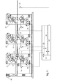
- Fig. 1 shows a schematic section through three of a web 02, z. B. web 02 or substrate web 02, in particular paper web 02, successively passed printing units 05, z. B. printing 05 for perfecting, especially offset printing 05 for perfecting.
- the printing units 05 can also in other ways, for. B. as a three-cylinder offset printing units 05, as a direct or flexo printing, as a printing unit for the high pressure or gravure printing or different from each other.
- At least one, but preferably two of the printing units 05 have in the inlet and / or outlet region of the printing gap 10, a guide element 01, z. B. Bahnleitelement 01, which, when in operative contact with the web 02, a web running through the printing unit 05 allows such that the web 02 is guided without contact through the pressure nip 10.
- the printing unit 05 may in principle be associated with a single such guide element 01, which allows an above-mentioned web run.
- the above-mentioned non-contact web run is arranged by a in Eingans- and one in the outlet region of the pressure nip 10 Guiding element 01 causes.
- the printing unit 05 has in the input and / or outlet area in each case a Bruleitelement 01 in order to be able to guide an already printed web 02 contactlessly through the printing nip 10 when the printing point is stopped.
- This printing unit 05 is operable as an imprinting unit 05 or as a printing unit 05 for the flying printing form change in alternation with a second such printing unit 05.
- the web 02 is printed by one of the printing units 05 while it passes through the other of these printing units 05 without contact. In the other operating situation, the opposite occurs.
- the two web guiding elements 01 are z. B.
- the printing machine has five printing units 05, wherein in one mode of operation one of the five printing units 05 is passed through without contact, while the web 02 is printed in four colors (eg on both sides) by the remaining four printing units 05.
- the previously contactless printing unit 05 is set in the printing mode while one of the four previously printing printing units 05 is passed through without contact.
- At least the two contactless pressure units 05 which are to be passed without contact, have the guide elements 01 at least in the inlet region, but in particular in the inlet and outlet regions of the pressure gap 10.
- the described alternate operation is performed by the first two of the five pressure units 05, wherein these are carried out according to the guide elements 01.
- the first printing unit 05 then has, at least in the outlet region, the second in the outlet and inlet region, for example, essentially non-contact, z. B. luftum Crowte, vanes 01 on.
- a guide element 01 embodied as a conventional guide roller 01 can be rotatably mounted in the side frame.
- the web-guiding element 01 in the outlet region of at least one of the two printing units 05 provided for alternate printing is arranged to be movable relative to a direction with a component perpendicular to the plane of the web 02.
- the Bahnleitelement 01 is adapted to be brought by moving the same with the web 02 in operative contact or out of operative contact.
- the web 02 is deflected coming from a direct path from the pressure nip 10 coming. If the guide element 01 is in operative contact (position A), then the web 02 undergoes a change in its path of travel as compared to that of the position B as shown.
- Fig. 10 schematically shows the aforementioned facts with reference to a first and a second, subsequent printing unit 05 (only partially shown and denoted by 05.1 and 05.2).
- a first and a second, subsequent printing unit 05 are only partially shown and denoted by 05.1 and 05.2.
- the first printing unit 05.1 in the entry and exit area of its printing gap 10 each have a guide element 01 for the corresponding guidance of the web 02.
- the two guide element 01 are in such a position A that the web 02 passes the pressure gap 10 at pressure-Ab (AB) without contact.
- they can in principle be arranged in a fixed position with respect to the web 02 in the printing unit 05.1 (05.2).
- the guide element 01 in the entrance area can be arranged as a rotatable guide roller 01 in the frame of the printing unit 05.1 stationary.
- At least the guide element 01 in the outlet region is arranged so as to be movable in its position with respect to a direction with a component perpendicular to the plane of the web 02.
- Fig. 10 it is in position A and allows the contactless passage of the web 02 by the printing unit 05.1. If it moved in position B, it would no longer be in contact with the web 02 and would not force them into the web guide shown in solid line. In that case, would the web 02 from the surface of the (upper) cylinder 21, z. B. transfer cylinder 21 on a direct path to the printing nip 10 of the next printing unit 05.2 or one of these next printing unit 05.2 associated guide element 01 run.
- the guide element 01 is also mounted in the inlet region such that it can be selectively brought into the two positions A and B.
- a straight and thus undisturbed web run can be achieved through the printing group 05.1 (05.2).
- the wrapping of the cylinders 21 required for the low-pressure printing is ensured, for example, by the offset of the centers of rotation of the cylinders 21 relative to each other in the horizontal direction (eg angle ⁇ to the vertical) ( Fig. 1 ).
- the second printing unit 05.2 has in the entry and exit area of its printing gap 10 each have a guide element 01 for the corresponding guidance of the web 02.
- the printing gap 10 forming cylinder 21, here two transfer cylinders 21, are located or the second printing unit 05.2 is in the print-on position (AN).
- the guide element 01 is arranged movably in its position with respect to a direction with a component perpendicular to the plane of the web 02 and in this case from the direct web path between the press nip 10 and a downstream guide element (not shown) Guide element 01) or a subsequent pressure nip 10 or a subsequent processing stage removed. Ie. it is in a position B in which it does not interact with the track 02 to guide it.
- the freshly printed in the second printing unit 05.2 web 02 thus does not interact in direct connection to the printing with this printing 05.2 associated guide 01.
- the risk of damaging the fresh print image, z. B. by greasing, is significantly reduced. If the web 02 comes into operative contact with a guide element 01 or with a subsequent processing step in the input region of a subsequent printing unit 05, then the ink has already largely penetrated the web 02 ("knocked off").
- At least two printing units 05 provided for the alternate printing each have at least in their outlet area a in o. G. Way movable guide element 01 on.
- at least the guide element 01 arranged in the outlet region is the pressure element 05.1; 05.2, d. H. placed outside the web path in position B, while in the corresponding, not in pressure printing unit 05.2; 05.1 that the guide element 01 arranged in the outlet region is brought into the path of the web 02 in such a way that it releases the printing unit 05.2; 05.1 can pass through without contact.
- the arrangement of the located in the outlet area movable guide element 01 is shown so that it is in the parked position B above the undisturbed web 02 and the web 02 deflects in the position A downwards, but this is applied in the same way to the opposite case , namely position B below the web plane and deflection of the web 02 upwards.
- the latter is particularly advantageous if an imaginary, the rotation centers of the cooperating cylinder 21 connecting line with respect to the vertical in reverse to in Fig. 10 is inclined as ⁇ , ie, for example - ⁇ . It is essential that the position B of the guide element 01 is selected such that no deflection of the web 01 by the guide element 01 takes place in this position.
- the guide elements 01 are also arranged movably in the described manner in the input manner, they are switched on or off in a further development in the same way as those in the outlet region.
- the print-on (AN) in each case one (except for the offset due to the angle ⁇ ) is level or at least in the region of the relevant printing unit 05.1; 05.2 substantially undisturbed web run, while in pressure-down (AB) of the s-shaped web run, as in Fig. 10 for the first printing unit 05.1 shown, is present.
- the movable guide elements 01 preferably have (in Fig. 1 only symbolically shown for the guide elements 01 in the outlet area) drives 22, by means of which the guide elements 01 of position A in B and vice versa can be brought.
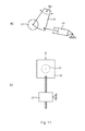
- These can, as in Fig. 11 shown schematically, for example, be designed as a pressure means to be actuated cylinder 22, which on a guide element 01 supporting, in a frame, not shown, of the printing unit 05; 05.1; 05.2 stored lever 32 act ( Fig. 11 a) ).
- they can also be embodied as electric motors 22 (for example via spindle drive), which have a pivoting movement of a lever 32 or a linear movement of a slide 32 carrying the guide element 01 (FIG. Fig. 11b) ).
- the linear movement can also with a cylinder 22 off Fig. 11 a) and the pivoting movement be driven by a motor.
- Drive mechanisms, in particular drives 22 are advantageously arranged in the region of both end faces of the guide element 01.
- the guide element 01 is schematically indicated here as a rotationally symmetrical body.
- a pivot axis S01 for the guide element 01 is preferably outside its geometry and therefore has a large travel. In the case of linear motion, this lies at infinity.
- the placement of the movable guide elements 01 via the drives 22 is preferably carried out remotely, z. B. by a common control device 23.
- the control device 23 for example, the output of the control command for the drives 22 in conjunction with the current and / or forthcoming operating situation of the respective provided for alternate printing unit 05.1; 05.2.
- the control device 23 when changing from one to the other printing unit 05.1; 05.2 automatically causes the placement of the guide elements 01 in such a way that the above web guide (just when in pressure and deflected - eg S-shaped - in the parked printing 05.1, 05.2) is achieved.
- the control device 23 thus operates in such a way that in a first operating situation when printing with the first printing unit 05.1 and plate change on the second printing 05.2 at least the downstream guide element 01 of the first printing unit turned off 05.1 and at least the downstream guide element 01 of the second printing unit 05.1 is employed and reversed in a second operating situation ( Fig. 10 ).
- the control device 23 has for time sequence control, in particular for synchronizing the adjusting movement of the cylinder 21 and the adjusting movement of the guide elements 01, for example, an interface to a change controlling controller or machine control 25, or it is integrated in the latter.
- the control device 23 can also at each provided for alternate printing unit 05.1; 05.2 be provided specifically, in which case, for example, a corresponding synchronization of the respective printing unit 05.1; 05.2 associated printing unit control, z. B. a printing unit PLC, forth or done a triggered by the placement of the cylinder 21 initiator.
- a change in the rotational position of the printing unit 05, in particular of the forme cylinder, not shown, made by, for example, a relative angular position of the relevant printing unit 05.i or its forme cylinder influencing actuator or a current setpoint for the relative angular position with a correction or difference is charged.
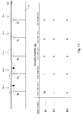
- This difference correlates with the described path change when changing the operating situation and can, for example, be in tabular form (see, for example, FIG. Fig. 13 ) for the possibly involved printing units 05; 05.1; 05.2 as corrections ⁇ 1 ; ⁇ 2 ; ⁇ 3 ; (With as one of the printing units, z. B.
- the relative angular positions will change of printing units 05 to be corrected, for example by the corrections ⁇ 1 ; ⁇ 2 ; ⁇ 3 ; changed, while the next change back to the first mode, the corrections - ⁇ 1 ; - ⁇ 2 ; - ⁇ 3 ; be made.
- control device 23 is logically connected, for example, to the arithmetic and / or memory unit 26 in such a manner that the position ⁇ 1 of the angular position compensating for the path change is compensated by the positions of the guide elements 01 at one or more of the printing units 05; 05.1; 05.2 takes place.
- this correction is carried out at least one setpoint value for the angular position to a basic state of the printing machine in a mode for the normal multi-color printing, hereinafter referred to as "normal operation" (in contrast to the "Imprint prepare").
- control device 23 and the arithmetic and / or memory unit 26 can be in signal communication with one another, for example, wherein the arithmetic and / or memory unit 26 receives the information relevant for the change (eg time, path change and / or relevant printing unit 05). receives from the controller 23 or the machine controller 25.
- information relevant for the change eg time, path change and / or relevant printing unit 05.
- normal operation can preferably be defined in a first embodiment by a web guide in which the web 02 is guided through all of these web 02 associated printing 05.i and would be printed by all these, ie printed by all printing 05.i simultaneously would (as opposed to Imprint ceremonies).
- "normal state" for example, by trial printing ("impressions") or mathematically by determining the web path and the printing section length, the offset angle and thus the relative angular positions
- the ground state is characterized by the fact that the web 02 occupies exactly the same for the printing with all associated printing units 05.i position or would take.
- the position of the web 02 is to be considered in the print-on position for the ground state.
- guide elements 01 are pivoted into the web path for non-contact operation and are swiveled away again for the printing operation of the relevant printing unit 05.1, the last-mentioned position of the web 02 must be taken into account for the ground state.
- Fig. 13 an advantageous embodiment of the method using the example of a plurality, here five printing units 05 or printing units 05 having printing machine explained:
- the first two of the web 02 associated pressure units 05.1; 05.2 the alternately usable pressure units 05.1; 05.2 for the Imprint prepare.
- the five printing units 05 are each mechanically independent of each other by not shown drives 24 (see Fig.
- each printing unit 05 is then made of this Leitachsposition ⁇ and the specific for each printing 05.i offset angle together, which takes into account the path length between the printing units and the printing length (cylinder circumference) in such a way that color separations imprinted by the printing units 05.i are applied to the web 02 in a pass-oriented manner.
- the drives 24 receive the Leitachsposition ⁇ and consider on the spot held there offsets angle , These offset angles are for example
- the offset angles are now for printing units 05.i or the associated drives 24 and / or angular positions the basic state or a mode B0 kept in normal operation, which as the basis or reference for operation or change to another mode of operation, for. B. in a mode B1; B2 of the Imprint Anlagenes is used.
- Above corrections ⁇ 1 ; ⁇ 2 ; ⁇ 3 ; can now switch between modes B0; B1; B2 related to this mode B0.
- Fig. 13 illustrates this situation by a trajectory through the five printing units 05.i for the mode B0 in normal operation (solid), a first mode B1 in imprint mode (dashed) and a second mode in imprint mode (dotted) is shown.
- the tabular overview gives an example of the required and reserved corrections ⁇ 1 ; ⁇ 2 ; ⁇ 3 ; per operating mode in the event that the first two of the printing units 05.i are provided for the alternating pressure. In the event, however, that other printing units 05.i would be provided for this purpose, the table deviates from that Fig.
- the first two printing units 05.1; 05.2 be used for the Imprint that the mode B0 of the ground state is used as a reference and that the correction "upstream", ie, a change to the first printing unit 05.1, and not made downstream.
- the Passerhaltmaschine between the printing units 05.i should be prepared by, for example, the first printing 05.1 remain in operation in the mode B1 in an unchanged ground state angular position, all the following, located in print-on printing units 05.3; 05.4; 05.5 be corrected. This would also change a cut register for a subsequent cross cutting and in turn would require a correction ⁇ S.
- the printing press has an automatic register device 27, wherein, for example, by at least one sensor 28, the relative position of successively by the printing units 05.1; 05.2; 05 etc. applied print images to each other in the longitudinal direction is determined, and in case of deviations from the desired state by the register means 27, a corresponding correction in the angular position ⁇ of one or more relevant printing units 05.1; 05.2; 05 etc. is made.
- a register device 27 while the error when changing the two o. G.
- At least the two web guiding elements 01 of the printing unit 05 executed for the mutual printing and / or at least the web guiding element 01 arranged in the outlet region of the printing gap 10 of at least one printing unit 05 are or is preferably formed as largely non-contact Bruleitelement 01, in particular as luftum Crowte rod 01, in the manner described below.
- the lateral surface of the guide element 01 has openings 03, z. B. micro-openings 03, through which in operation from an internal cavity 04, z. B. a chamber 04, in particular pressure chamber 04, under overpressure against the environment fluid standing, z. As a liquid, a gas or a mixture, in particular air, flows. In the figures, a corresponding supply of compressed air into the cavity 04 is not shown.
- the guide element 01 has, at least on the side cooperating with the web 02 or on the web 02 side facing its surface on the micro-openings 03. However, it can also have the openings 03 on other sides facing the web 02, or at least on its longitudinal section cooperating with the web 02 entirely made of a material comprising the microapertures 03.
- This simplest embodiment without preferential direction for the arrangement of the openings 03 is made possible by the formation of the openings 03 as micro-openings 03, since hereby created a thinner but more homogeneous air cushion, at the same time a required or resulting volume flow and thus a leakage current on the "open" side is considerably reduced.
- the high resistance of the micro-apertures 03 in contrast to large-cross-section apertures, causes "not capping" a range of apertures to result in a sort of short-circuit current. In the total resistance of the falling over the openings 03 partial resistance receives an increased weight.
- a first embodiment are the micro-openings 03 as open pores on the surface of a porous, especially microporous, air-permeable material 06, z. B. of an open-pore sintered material 06, in particular of sintered metal formed.
- the pores of the air-permeable porous material 06 have a mean diameter (average size) of less than 150 microns, z. B. 5 to 60 microns, in particular 10 to 30 microns.
- the material 06 is formed with an irregular, amorphous structure.
- Choice of material, dimensioning and pressurization are selected such that 1 to 20 standard cubic meters per m 2 , in particular 2 to 15 standard cubic meters per m 2 , emerge from the air outlet surface of the sintered material 06 per hour. Particularly advantageous is the air outlet of 3 to 7 standard cubic meters per m 2 .
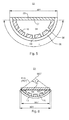
- this z. B tubular body formed substantially self-supporting with a wall thickness of greater than or equal to 2 mm, in particular greater than or equal to 3 mm ( Fig. 2 ). Possibly. can run in the cavity 04, a carrier on which the body can be selectively or partially supported, but which is not the entire surface in operative contact with the body.
- a body of porous material 06 can, as in Fig. 3 represented, also be formed shell-shaped.
- the guide elements 01 a fixed, at least partially permeable carrier 07, on which the microporous material 06 is applied as layer 06 ( Fig. 4 . 5 and 6 ).
- a carrier 07 can be acted upon with compressed air, which flows out of the carrier 07 through the microporous layer 06 and thus forms an air cushion on the surface of the guide element 01.
- the porous material 06 is thus not designed as a carrying solid body (with or without frame construction), but as a coating 06 on a bushings 08 or through holes 08 having, in particular metallic, carrier material.
- “non-bearing” layer 06 is understood to mean a structure, the layer 06 being supported over a plurality of supporting points of the carrier 07 over its entire layer length and entire layer width.
- the carrier 07 has z. B. on its acting together with the layer 06 width and length each have a plurality of non-contiguous passages 08.
- This embodiment is distinctly different from a design in which a porous material 06 extending over the entire width cooperating with the web 02 is designed to be self-supporting over this distance, is supported on a frame or carrier only in one end region, and therefore one must have appropriate strength.
- the carrier material essentially absorbs the weight, shear, torsional, bending and / or shear forces of the component, which is why a corresponding wall thickness (eg greater than 3 mm, in particular greater than 5 mm) of the carrier 07 and / or a suitably stiffened construction is selected.
- the z. B. the cavity 04 to 06 layer limiting, or by appropriate shaping (eg., In Fig. 4 tubular) forming the cavity 04 carrier 07 has on the side coated with the porous material 06 a plurality of openings 09 for supplying the compressed air into the porous material 06. Also in the openings 09 of the carrier 07 may be in the region of the walls z. T. porous material 06 are located.
- the guide element 01 as in the Fig. 4 . 5 and 6 shown, the carrier 07 also referred to as the main body 07 with the hollow or interior 04, z. B. a tubular support 07 ( Fig. 4 ), which in its wall radially up to the lateral surface has a plurality of through openings 09.
- the carrier 07 can in principle be designed with any hollow profile, but advantageously with an annular profile.
- a fluid for. B. gas, blown, which z. B. by a compressor, not shown, under a pressure P is greater than the ambient pressure.
- the cavity 04 is not formed by a tube designed as an annular carrier 07, but in a different geometry.
- the support 07 has a part-circular wall 15 or wall 15 (in particular with a fixed radius or radius of curvature R07 or R15 with respect to a fixed center M07), which is closed on its open side, for example, by a cover 20.
- This part-circular wall 15 with cover 20 may be made in one piece or several pieces but connected to each other.
- the pitch circle angle ⁇ of the openings 09 having wall 15 is selected to about 180 °.
- the radius R15 for the pitch circle (or the pipe as the raw material) is selected on the basis of the required deflection (deflection angle ⁇ of the change in direction of the track 02) and a corresponding pitch circle is taken. A deflection is thus possible “soft" and is on the available space in the largest possible area supported by the air cushion.
- the pitch circle angle ⁇ is selected to be 10 ° to 45 °, in particular between 15 ° to 35 °.
- the width b01 is selected, for example, to be 30 to 150 mm, in particular 50 to 110 mm.
- the radius of curvature R15 is for the wall 15, for example between 120 and 150 mm, in particular between 140 and 200 mm.
- the layer 06 can be as in Fig. 5 be extended to the frontal cover 20 or just cover the openings 09 receiving, curved wall 15 ( Fig. 6 ). The layer 06 may also be flattened in its outgoing region, forming a smooth transition.
- a width b01 of the guide element 01 or width b07 of the carrier 07 - for example a maximum width prescribed for space reasons - achieves the largest possible area of the air cushioning which is effective as a support.
- a desired or predetermined width b01 based on the required deflection (by way of example as the deflection angle ⁇ of the change in direction of the web 02 in FIG Fig. 1 in the first printing unit 05), the radius R07 for the pitch circle (or the pipe as the raw material) is selected and a corresponding pitch circle is taken.
- a deflection is thus as "soft" and is supported on the available space in the widest possible range by the air cushion.
- the radius of curvature R07 is then selected so that, taking into account the addition ⁇ , the desired width b01 or b07 is maintained.
- An optionally formed by the layer thickness supernatant can be neglected in the small thicknesses. With optimal use of space so a large effective area is created taking into account a security.
- openings 09 and / or layer 06 may include the full 360 ° angle, or only a partial circle.
- pitch circles profiles for the interacting with the web 02 area of the guide element 01 (or its curved wall 15) are conceivable, for example as a section of an ellipse, parabola or hyperbola.
- the curve shape of the deflection with respect to a "soft" deflection can be optimized.
- the pitch circle shape has advantages in terms of standardization, material consumption and simplified manufacturing.
- a guide element 01 wherein the porous material 06 is not largely supported by an opening 09 having carrier 07 or main body 07, but is supported, for example, only bridge-like on a frame-like support 07 in edge regions, has the formation of a circular, pitch circle -, elliptical, parabolic or hyperbolic body 07 directly under the layer 06 in terms of manufacturing, dimensional stability, cost and handling great advantages.
- the carrier 07 or its curved wall 15 and / or openings 09 or free cross sections have a diameter or a maximum inside width of 10 mm, in particular of less than or equal to 5 mm.
- the porous material 06 outside the feedthrough 08 has a layer thickness which is less than 1 mm. Particularly advantageous is a layer thickness between 0.05 mm and 0.3 mm.
- a proportion of open area in the area of the effective outer surface of the porous material, here referred to as opening degree, is between 3% and 30%, preferably between 10% and 25%.
- opening degree is between 3% and 30%, preferably between 10% and 25%.
- the thickness of the layer 06 at least equal to the distance between adjacent openings 09 of the carrier 07.
- the wall thickness of the carrier 07 is - at least in the layer 06 having region - greater than 3 mm, in particular greater than 5 mm, executed.
- the possibly with a hollow profile designed carrier 07 may in turn also made of porous material 06, but with a better air permeability -.
- the openings 09 of the carrier 07 are formed by open pores in the region of the surface, and the passages 08 are formed by the randomly formed via the porosity inside the channels.
- the support 07 can also be formed from any desired, the cavity 04 enclosing, provided with bushings 08 flat material or molded material. Combinations of these alternatives are also possible.
- a second embodiment ( Fig. 7 to 9 ) are the micro-openings 03 as openings through holes 11, in particular microbores 11 executed, which is characterized by a z. B. as a pressure chamber 04 formed cavity 04 delimiting wall 12, z. B. chamber wall 12, extend outward.
- the holes 11 have z. B. a diameter (at least in the region of the openings 03) of less than or equal to 500 .mu.m, advantageously less than or equal to 300 .mu.m, in particular between 60 and 150 .mu.m. Of the Opening degree is z. From 3% to 25%, especially from 5% to 15%.
- a hole density is at least 1 / (5 mm 2 ), in particular at least 1 / mm 2 up to 4 / mm 2 .
- the wall 12 thus has, at least in one of the web 02 opposite region, a microperforation.
- the microperforation extends over the region which interacts with the web 02; However, it can - as in the first embodiment, the bushings 08 and layer 06 - extend to the full extent of 360 °, as the losses are kept within limits as mentioned.
- FIG. Fig. 8 In a second example for the execution of the guide element 01 with microbores 11 (FIG. Fig. 8 ) is the chamber wall 12 on the web 02 side facing a curved wall 14 and a curved wall portion 14 - comparable to the FIGS. 5 and 6 described wall 15 - on, which has the microbores 11. That to the angles ⁇ , ⁇ , ⁇ and the widths b01 and b07 (here b01 and b12, respectively) and the radius R15 (here R14) to FIGS. 5 and 6 said, as well as the procedure and selection of the radii of curvature is to be transferred in the same way to the present example.
- the wall 14 having the microbores 11 is designed as an insert 14 or as a plurality of inserts 14 arranged next to one another in the axial direction in a carrier 16.
- the insert 14 may be fixed or detachable or changeable connected to the carrier 16.
- the latter is advantageous in terms of cleaning or exchanging inserts 14 of different types of microperforations for adaptation to different materials (mass and / or surface structure) and web widths.
- such inserts 14 may be arranged, for example, on a running in the cavity 04 support 16.
- an embodiment is advantageous, wherein, as shown, the insert 09 comprising the openings 09 is formed merely by means of an angular segment with a curvature, in particular adapted to the web run.
- the curved surface of the insert 14 and the inserts 14 is again to the angles ⁇ , ⁇ , ⁇ and the widths b01 and b07 (here b01 and b12) and the radius R15 (here R14) to FIGS. 5 and 6 as well as the procedure and selection of the radii of curvature in the same way to the present example.
- a projection required for the connection between the application width and the carrier width is to be taken into account.
- the curvature may, for example, be enforced by an intended excess width of the insert 14 relative to the support 16 (or its attachment means) as resulting bending.
- the releasable connection can be realized as shown for example by the ends of the insert 14 receiving grooves 17 in the carrier 16.
- a connection can be made by screwing or by bracing.
- the wall thickness of the borehole 11 containing chamber wall 12 (or wall 14 or insert 14) influencing the flow resistance can be from 0.2 to 3.0 mm, advantageously from 0.2 to 1.5 mm, in particular from 0, for all relevant examples , 3 to 0.8 mm, lie.
- a reinforcing construction not shown, for example, in the longitudinal direction of the guide element 01 extending carrier, in particular metal carrier, can be arranged, in particular at the smaller of said wall thicknesses, on which the chamber wall 12, the Wall 14 and the insert 14 at least partially or selectively supported. This can be done for example by mutually spaced apart in the axial direction ribs.
- an overpressure in the chamber 04 of 0.5 to 2 bar, in particular from 0.5 to 1.0 bar of Advantage.
- the bores 11 may be cylindrical, funnel-shaped or else of a special shape (for example in the form of a Laval nozzle).
- the microperforation, d. H. the bores 11 are preferably produced by drilling by means of accelerated particles (eg liquid such as water jet, ions or elementary particles) or by means of electromagnetic radiation of high energy density (eg light by means of a laser beam). Particularly advantageous is the production by means of electron beam.
- accelerated particles eg liquid such as water jet, ions or elementary particles
- electromagnetic radiation of high energy density eg light by means of a laser beam
- the web 02 facing side of the holes 11 having wall 12 (14), z.
- a stainless steel formed wall 12 (14) in a preferred embodiment, a dirt and / or color-repellent finish. It has a not shown, the openings 03 and holes 11 not covering coating -.
- the guide element 01 possibly also in execution without the pivoting about a lying outside its geometry pivot axis S01 after Fig. 10 , the guide element 01 blown with compressed air is mounted so as to be rotatable in relation to a longitudinal axis lying within its geometry.
- the guide element 01 such as in Fig. 3 . 5 . 6 . 8 or 9 shown, not rotationally symmetrical with openings 03 and / or bushings 08 is executed, or if the shape of the guide element 01 viewed in cross-section is adapted to a web guide such that it is not rotationally symmetrical.
- the guide element 01 viewed in the circumferential direction has a preferential direction with respect to the web 02.
- the guide element 01 is rotatable with respect to a longitudinal axis A01, which lies within its outer geometric dimensions. This has the consequence that primarily a twisting takes place, and not a pivoting about an external pivot axis S01. A twisting and possibly pivoting after Fig. 10 are more decoupled.
- the guide element 01 is arranged for example in a holder 29, which in turn, for. B. via bearings 30, is rotatably mounted in a frame 31.
- the frame 31 may in the case of a stationary arranged guide element 01 a side frame 31 of the printing unit 05; 05.1; 05.2, or in the case of according to Fig. 10 movable guide element 01 is a lever 32 or slide 32, which is opposite to the side frame of the printing unit 05, not shown for this case; 05.1; 05.2 is movable.
- the guide element 01 or the holder 29 is rotatable by a drive 33 about the longitudinal axis A01.
- the drive 33 is designed as a worm drive 33 and has a worm wheel 34 connected in a rotationally fixed manner to the mount 29 and a worm 36. It is particularly advantageous that the drive 33 has a gearbox with a strong reduction to the guide element 01 out.
- the worm drive 34 can be operated either manually by the operator - for example, via a polygon connected to the worm 36 by a key -.
- a motor 37 is provided, which is locally or remotely operated - for example, from a control room ago - operated.
- the drive 33 and possibly the motor 37 are in the embodiment as a pivotable guide element 01 (according to Fig. 10 ) are arranged on the guide element 01 supporting lever 32 or carriage 32.
- the drive 33 can be arranged directly, without a holder 29, acting on the guide element 01.
- the holder 29 it may be advantageous, however, with respect to the angular position of a uniqueness connection 38 between the guide 01 and bracket 29, here z.
Landscapes
- Engineering & Computer Science (AREA)
- Mechanical Engineering (AREA)
- Registering, Tensioning, Guiding Webs, And Rollers Therefor (AREA)
- Rotary Presses (AREA)
- Inking, Control Or Cleaning Of Printing Machines (AREA)
Applications Claiming Priority (2)
| Application Number | Priority Date | Filing Date | Title |
|---|---|---|---|
| DE102004009861A DE102004009861B4 (de) | 2004-03-01 | 2004-03-01 | Verfahren und Vorrichtung für den Betrieb von Druckeinheiten |
| EP05707982A EP1720704A1 (fr) | 2004-03-01 | 2005-02-09 | Procede et dispositif pour le fonctionnement d'unites d'impression et element de guidage |
Related Parent Applications (1)
| Application Number | Title | Priority Date | Filing Date |
|---|---|---|---|
| EP05707982A Division EP1720704A1 (fr) | 2004-03-01 | 2005-02-09 | Procede et dispositif pour le fonctionnement d'unites d'impression et element de guidage |
Publications (1)
| Publication Number | Publication Date |
|---|---|
| EP1900520A2 true EP1900520A2 (fr) | 2008-03-19 |
Family
ID=34894894
Family Applications (2)
| Application Number | Title | Priority Date | Filing Date |
|---|---|---|---|
| EP07123645A Withdrawn EP1900520A2 (fr) | 2004-03-01 | 2005-02-09 | Procédé pour le fonctionnement alterné d'une première et d'une seconde unité d'impression traversées par une bande |
| EP05707982A Withdrawn EP1720704A1 (fr) | 2004-03-01 | 2005-02-09 | Procede et dispositif pour le fonctionnement d'unites d'impression et element de guidage |
Family Applications After (1)
| Application Number | Title | Priority Date | Filing Date |
|---|---|---|---|
| EP05707982A Withdrawn EP1720704A1 (fr) | 2004-03-01 | 2005-02-09 | Procede et dispositif pour le fonctionnement d'unites d'impression et element de guidage |
Country Status (3)
| Country | Link |
|---|---|
| EP (2) | EP1900520A2 (fr) |
| DE (1) | DE102004009861B4 (fr) |
| WO (1) | WO2005082619A1 (fr) |
Families Citing this family (7)
| Publication number | Priority date | Publication date | Assignee | Title |
|---|---|---|---|---|
| DE102005053162A1 (de) * | 2005-11-08 | 2007-05-10 | Man Roland Druckmaschinen Ag | Druckmaschine und Verfahren zum Betreiben derselben |
| DE102006013956B4 (de) * | 2006-03-27 | 2008-02-07 | Koenig & Bauer Aktiengesellschaft | Druckmaschine mit einer Einrichtung zum Zuführen einer Materialbahn und ein Verfahren zum Zuführen einer Materialbahn |
| DE102006013954B4 (de) | 2006-03-27 | 2008-03-06 | Koenig & Bauer Aktiengesellschaft | Druckmaschine mit einer Einrichtung zum Zuführen einer Materialbahn |
| DE102007063577A1 (de) * | 2007-02-17 | 2008-09-04 | Koenig & Bauer Aktiengesellschaft | Verfahren zum Betreiben einer Satellitendruckeinheit |
| DE102008041238A1 (de) | 2008-08-13 | 2010-02-25 | Koenig & Bauer Aktiengesellschaft | Druckeinheit einer Druckmaschine |
| DE102012013435A1 (de) * | 2012-04-04 | 2013-10-10 | Robert Bosch Gmbh | Verfahren zur Vorregistrierung einerBearbeitungsstation |
| DE102013207151A1 (de) * | 2013-04-19 | 2014-11-06 | Robert Bosch Gmbh | Formschulter einer Schlauchbeutelverpackungsmaschine |
Citations (6)
| Publication number | Priority date | Publication date | Assignee | Title |
|---|---|---|---|---|
| US3744693A (en) | 1970-05-29 | 1973-07-10 | Roland Offsetmaschf | Turning bar for the deflection of paper webs |
| DE9311113U1 (de) | 1993-07-26 | 1993-09-09 | Zirkon Druckmaschinen GmbH Leipzig, 04328 Leipzig | Eindruckwerk für fliegend wechselnde Eindrucke |
| US5423468A (en) | 1990-05-11 | 1995-06-13 | Liedtke; Rudolph J. | Air bearing with porous outer tubular member |
| US5617788A (en) | 1993-05-14 | 1997-04-08 | Toshiba Kikai Kabushiki Kaisha | Switching type continuously operative printing machine |
| DE10008936A1 (de) | 2000-02-25 | 2001-08-30 | Roland Man Druckmasch | Rollenrotations-Offsetdruckmaschine |
| JP2002114419A (ja) | 2000-10-05 | 2002-04-16 | Mitsubishi Heavy Ind Ltd | 印刷機の紙パス変更装置 |
Family Cites Families (7)
| Publication number | Priority date | Publication date | Assignee | Title |
|---|---|---|---|---|
| DE4327646C5 (de) * | 1992-10-23 | 2006-04-27 | Kabushiki Kaisha Tokyo Kikai Seisakusho | Breiten-Einstellverfahren für eine Papierbahn sowie damit ausgerüstete lithographische Rotationspresse |
| DE4430693B4 (de) * | 1994-08-30 | 2005-12-22 | Man Roland Druckmaschinen Ag | Antriebe für eine Rollenrotations-Offsetdruckmaschine |
| DE19614397C2 (de) * | 1996-04-12 | 2001-04-26 | Roland Man Druckmasch | Antrieb mit Registervorrichtung für eine Druckeinheit einer Rollenrotationsdruckmaschine |
| JP2001114419A (ja) * | 1999-10-15 | 2001-04-24 | Murata Mach Ltd | コンベア装置 |
| DE10132156C5 (de) * | 2001-07-03 | 2011-12-01 | Manroland Ag | Bahnstabilisierung zur berührungslosen Bahnführung bei fliegend wechselbaren Druckeinheiten |
| DE20303720U1 (de) * | 2003-02-07 | 2003-05-15 | MAN Roland Druckmaschinen AG, 63075 Offenbach | Bahnführung in einer Rollenrotatinsdruckmaschine |
| DE20309429U1 (de) * | 2003-06-17 | 2003-09-18 | Reifenhäuser GmbH & Co. Maschinenfabrik, 53844 Troisdorf | Abzugsvorrichtung einer Schlauchfolienextrusionsanlage |
-
2004
- 2004-03-01 DE DE102004009861A patent/DE102004009861B4/de not_active Expired - Fee Related
-
2005
- 2005-02-09 EP EP07123645A patent/EP1900520A2/fr not_active Withdrawn
- 2005-02-09 EP EP05707982A patent/EP1720704A1/fr not_active Withdrawn
- 2005-02-09 WO PCT/EP2005/050563 patent/WO2005082619A1/fr not_active Ceased
Patent Citations (6)
| Publication number | Priority date | Publication date | Assignee | Title |
|---|---|---|---|---|
| US3744693A (en) | 1970-05-29 | 1973-07-10 | Roland Offsetmaschf | Turning bar for the deflection of paper webs |
| US5423468A (en) | 1990-05-11 | 1995-06-13 | Liedtke; Rudolph J. | Air bearing with porous outer tubular member |
| US5617788A (en) | 1993-05-14 | 1997-04-08 | Toshiba Kikai Kabushiki Kaisha | Switching type continuously operative printing machine |
| DE9311113U1 (de) | 1993-07-26 | 1993-09-09 | Zirkon Druckmaschinen GmbH Leipzig, 04328 Leipzig | Eindruckwerk für fliegend wechselnde Eindrucke |
| DE10008936A1 (de) | 2000-02-25 | 2001-08-30 | Roland Man Druckmasch | Rollenrotations-Offsetdruckmaschine |
| JP2002114419A (ja) | 2000-10-05 | 2002-04-16 | Mitsubishi Heavy Ind Ltd | 印刷機の紙パス変更装置 |
Also Published As
| Publication number | Publication date |
|---|---|
| DE102004009861B4 (de) | 2007-09-20 |
| WO2005082619A1 (fr) | 2005-09-09 |
| EP1720704A1 (fr) | 2006-11-15 |
| DE102004009861A1 (de) | 2005-09-29 |
Similar Documents
| Publication | Publication Date | Title |
|---|---|---|
| EP1556219B1 (fr) | Elements de guidage pour unite d'impression | |
| EP1820645B1 (fr) | Presse rotative dotée d'un dispositif de pliage | |
| DE20221942U1 (de) | Druckeinheit | |
| EP2006098A2 (fr) | System zur Aufbereitung von Bearbeitungsöl | |
| EP1104347B1 (fr) | Dispositif de retenue pour manchons d'impression flexographique | |
| EP1900520A2 (fr) | Procédé pour le fonctionnement alterné d'une première et d'une seconde unité d'impression traversées par une bande | |
| EP1742793B1 (fr) | Groupe d'impression offset d'une imprimeuse destinee a l'impression de journaux | |
| DE102004007374B3 (de) | Vorrichtungen zum berührunglosen Abtasten einer Bahn | |
| DE10349890B4 (de) | Vorrichtung zum Längsschneiden einer Bahn | |
| EP1594784B1 (fr) | Machine a imprimer une matiere en forme de bande | |
| DE102004018401A1 (de) | Verfahren und Vorrichtung zur Voreinstellung einer Druckmaschine | |
| DE102004007378B4 (de) | Vorrichtungen zur Beeinflussung der Breite und/oder Lage einer Bahn | |
| EP1502887B1 (fr) | Procédé de préréglage d'une machine d'impression | |
| WO1989008027A1 (fr) | Agencement de dosage d'un liquide fourni au cylindre de la plaque d'impression d'une imprimante, par exemple pour le dosage de la solution de mouillage du cylindre de la plaque d'impression d'une machine offset | |
| DE29601150U1 (de) | Drehbarer Körper | |
| DE102006028434A1 (de) | Druckeinheit einer Druckmaschine mit mindestens zwei Druckwerken sowie Rollenoffsetdruckmaschinen mit einer Mehrzahl von Druckwerken | |
| EP1908588A2 (fr) | Machine d'impression rotative avec une unité d'impression comprenant un cylindre de plaques | |
| DE29601151U1 (de) | Zylindrischer Körper | |
| DE202004021518U1 (de) | Druckmaschinen | |
| DE202006020589U1 (de) | Neun-Zylinder-Satellitendruckeinheit und ein Druckturm | |
| DE202006019789U1 (de) | Druckeinheit einer Druckmaschine mit mindestens zwei Druckwerken sowie Rollenoffsetdruckmaschinen mit einer Mehrzahl von Druckwerken | |
| WO2007099148A2 (fr) | Groupes d'impression d'une machine à imprimer |
Legal Events
| Date | Code | Title | Description |
|---|---|---|---|
| PUAI | Public reference made under article 153(3) epc to a published international application that has entered the european phase |
Free format text: ORIGINAL CODE: 0009012 |
|
| AC | Divisional application: reference to earlier application |
Ref document number: 1720704 Country of ref document: EP Kind code of ref document: P |
|
| AK | Designated contracting states |
Kind code of ref document: A2 Designated state(s): AT BE BG CH CY CZ DE DK EE ES FI FR GB GR HU IE IS IT LI LT LU MC NL PL PT RO SE SI SK TR |
|
| STAA | Information on the status of an ep patent application or granted ep patent |
Free format text: STATUS: THE APPLICATION HAS BEEN WITHDRAWN |
|
| 18W | Application withdrawn |
Effective date: 20090306 |