EP1900554A1 - Suspension de roue unique de type à bras transversaux superposés - Google Patents
Suspension de roue unique de type à bras transversaux superposés Download PDFInfo
- Publication number
- EP1900554A1 EP1900554A1 EP07017369A EP07017369A EP1900554A1 EP 1900554 A1 EP1900554 A1 EP 1900554A1 EP 07017369 A EP07017369 A EP 07017369A EP 07017369 A EP07017369 A EP 07017369A EP 1900554 A1 EP1900554 A1 EP 1900554A1
- Authority
- EP
- European Patent Office
- Prior art keywords
- wheel suspension
- suspension according
- independent wheel
- longitudinal
- independent
- Prior art date
- Legal status (The legal status is an assumption and is not a legal conclusion. Google has not performed a legal analysis and makes no representation as to the accuracy of the status listed.)
- Granted
Links
- 239000000725 suspension Substances 0.000 title claims abstract description 63
- 230000005540 biological transmission Effects 0.000 claims abstract 2
- 238000005516 engineering process Methods 0.000 claims description 2
- 238000013016 damping Methods 0.000 claims 1
- 238000000465 moulding Methods 0.000 claims 1
- 238000010276 construction Methods 0.000 description 9
- 239000000969 carrier Substances 0.000 description 3
- 239000006096 absorbing agent Substances 0.000 description 2
- 239000002184 metal Substances 0.000 description 2
- 230000003014 reinforcing effect Effects 0.000 description 2
- 230000035939 shock Effects 0.000 description 2
- 239000003381 stabilizer Substances 0.000 description 2
- 229910000831 Steel Inorganic materials 0.000 description 1
- 238000010521 absorption reaction Methods 0.000 description 1
- 238000005452 bending Methods 0.000 description 1
- 230000008878 coupling Effects 0.000 description 1
- 238000010168 coupling process Methods 0.000 description 1
- 238000005859 coupling reaction Methods 0.000 description 1
- 238000011161 development Methods 0.000 description 1
- 230000018109 developmental process Effects 0.000 description 1
- 230000010354 integration Effects 0.000 description 1
- 230000003993 interaction Effects 0.000 description 1
- 238000004519 manufacturing process Methods 0.000 description 1
- 238000007493 shaping process Methods 0.000 description 1
- 230000006641 stabilisation Effects 0.000 description 1
- 238000011105 stabilization Methods 0.000 description 1
- 239000010959 steel Substances 0.000 description 1
Images

Classifications
-
- B—PERFORMING OPERATIONS; TRANSPORTING
- B62—LAND VEHICLES FOR TRAVELLING OTHERWISE THAN ON RAILS
- B62D—MOTOR VEHICLES; TRAILERS
- B62D21/00—Understructures, i.e. chassis frame on which a vehicle body may be mounted
- B62D21/02—Understructures, i.e. chassis frame on which a vehicle body may be mounted comprising longitudinally or transversely arranged frame members
-
- B—PERFORMING OPERATIONS; TRANSPORTING
- B60—VEHICLES IN GENERAL
- B60G—VEHICLE SUSPENSION ARRANGEMENTS
- B60G3/00—Resilient suspensions for a single wheel
- B60G3/18—Resilient suspensions for a single wheel with two or more pivoted arms, e.g. parallelogram
- B60G3/20—Resilient suspensions for a single wheel with two or more pivoted arms, e.g. parallelogram all arms being rigid
-
- B—PERFORMING OPERATIONS; TRANSPORTING
- B60—VEHICLES IN GENERAL
- B60G—VEHICLE SUSPENSION ARRANGEMENTS
- B60G7/00—Pivoted suspension arms; Accessories thereof
- B60G7/02—Attaching arms to sprung part of vehicle
-
- B—PERFORMING OPERATIONS; TRANSPORTING
- B60—VEHICLES IN GENERAL
- B60G—VEHICLE SUSPENSION ARRANGEMENTS
- B60G2200/00—Indexing codes relating to suspension types
- B60G2200/10—Independent suspensions
- B60G2200/14—Independent suspensions with lateral arms
- B60G2200/144—Independent suspensions with lateral arms with two lateral arms forming a parallelogram
-
- B—PERFORMING OPERATIONS; TRANSPORTING
- B60—VEHICLES IN GENERAL
- B60G—VEHICLE SUSPENSION ARRANGEMENTS
- B60G2200/00—Indexing codes relating to suspension types
- B60G2200/40—Indexing codes relating to the wheels in the suspensions
- B60G2200/44—Indexing codes relating to the wheels in the suspensions steerable
-
- B—PERFORMING OPERATIONS; TRANSPORTING
- B60—VEHICLES IN GENERAL
- B60G—VEHICLE SUSPENSION ARRANGEMENTS
- B60G2204/00—Indexing codes related to suspensions per se or to auxiliary parts
- B60G2204/10—Mounting of suspension elements
- B60G2204/12—Mounting of springs or dampers
- B60G2204/126—Mounting of pneumatic springs
-
- B—PERFORMING OPERATIONS; TRANSPORTING
- B60—VEHICLES IN GENERAL
- B60G—VEHICLE SUSPENSION ARRANGEMENTS
- B60G2204/00—Indexing codes related to suspensions per se or to auxiliary parts
- B60G2204/10—Mounting of suspension elements
- B60G2204/12—Mounting of springs or dampers
- B60G2204/128—Damper mount on vehicle body or chassis
-
- B—PERFORMING OPERATIONS; TRANSPORTING
- B60—VEHICLES IN GENERAL
- B60G—VEHICLE SUSPENSION ARRANGEMENTS
- B60G2204/00—Indexing codes related to suspensions per se or to auxiliary parts
- B60G2204/10—Mounting of suspension elements
- B60G2204/14—Mounting of suspension arms
- B60G2204/143—Mounting of suspension arms on the vehicle body or chassis
-
- B—PERFORMING OPERATIONS; TRANSPORTING
- B60—VEHICLES IN GENERAL
- B60G—VEHICLE SUSPENSION ARRANGEMENTS
- B60G2204/00—Indexing codes related to suspensions per se or to auxiliary parts
- B60G2204/40—Auxiliary suspension parts; Adjustment of suspensions
- B60G2204/43—Fittings, brackets or knuckles
-
- B—PERFORMING OPERATIONS; TRANSPORTING
- B60—VEHICLES IN GENERAL
- B60G—VEHICLE SUSPENSION ARRANGEMENTS
- B60G2206/00—Indexing codes related to the manufacturing of suspensions: constructional features, the materials used, procedures or tools
- B60G2206/01—Constructional features of suspension elements, e.g. arms, dampers, springs
- B60G2206/60—Subframe construction
-
- B—PERFORMING OPERATIONS; TRANSPORTING
- B60—VEHICLES IN GENERAL
- B60G—VEHICLE SUSPENSION ARRANGEMENTS
- B60G2300/00—Indexing codes relating to the type of vehicle
- B60G2300/02—Trucks; Load vehicles
-
- B—PERFORMING OPERATIONS; TRANSPORTING
- B60—VEHICLES IN GENERAL
- B60G—VEHICLE SUSPENSION ARRANGEMENTS
- B60G2300/00—Indexing codes relating to the type of vehicle
- B60G2300/14—Buses
-
- B—PERFORMING OPERATIONS; TRANSPORTING
- B60—VEHICLES IN GENERAL
- B60G—VEHICLE SUSPENSION ARRANGEMENTS
- B60G2300/00—Indexing codes relating to the type of vehicle
- B60G2300/38—Low or lowerable bed vehicles
Definitions
- the invention relates to an independent suspension, wherein the wheel guide is based on the concept of the double wishbone axle.
- the wheel carrier element is connected to the vehicle frame via upper and lower control arms.
- the upper and lower control arms are on the one hand pivotally mounted on the vehicle frame and on the other hand hingedly connected to the wheel carrier.
- the vehicle longitudinal members designated by the reference numeral 1 form the essential supporting elements of the vehicle frame construction.
- Each suspension is associated with a vehicle longitudinal member, so that under the vehicle body, two vehicle longitudinal members are arranged, which are connected to one another via a plurality of cross member grid or box-like manner and form the vehicle frame.
- This classic and well-known design of a vehicle frame is also referred to as a ladder frame, since the cross members like the rungs and the side members look like the spars of a ladder.
- an auxiliary frame 2 is provided, to which the suspension is attached.
- This subframe assumes no independent support function for the high forces occurring during driving and / or in the event of a crash, but it is according to claim 1 on the vehicle frame, that is attached to the vehicle longitudinal members.
- the high, resulting in dynamic driving and in the event of a crash forces are absorbed by the longitudinal members of the vehicle frame, to which the subframe is connected via the gussets 14 and connection angle 15.
- the subframe itself is used only for attachment of the spring seat, the wishbone, trailing arm, shock absorbers and wheel, so to attach the suspension elements.
- the core idea of DE 200 22 516 U1 It is suspension and make subframe as a separate module regardless of the vehicle frame and then attach this module to the vehicle frame.
- the invention has for its object to provide an independent suspension for a vehicle axle with steerable wheels, on the one hand the largest possible space between two independent wheel suspension of an axle is available, and on the other hand leads to an increase in the rigidity of the overall structure of the vehicle frame.
- the length of the wishbone can be significantly reduced.
- the wishbones are connected directly to the side members of the vehicle frame, so that the entire space between the longitudinal members of the vehicle frame is not influenced and limited by the wishbone.
- each independent suspension is associated with a frame structure consisting of a first and a second side member.
- the upper arm of the independent suspension is connected to the first side member, while the lower arm is connected to the second side member.
- the second longitudinal member is arranged substantially parallel and spaced from the first longitudinal member, and the second longitudinal member is fixedly connected via connecting elements with the first longitudinal member.
- This construction makes it possible, viewed in the direction transverse to the vehicle longitudinal axis, to use short upper and in particular lower wishbones.
- These short wishbones can be connected directly to the frame structure and do not protrude beyond the longitudinal members of the vehicle frame in the direction of the vehicle center, so that they do not restrict the space between the longitudinal members.
- the cross-sectional enlargement can be realized by a shaping of the first longitudinal member pointing in the direction of the vehicle body. If the first side member is designed as a C-profile, it has an upper and a lower belt and a web connecting these belts. In this case, to realize the cross-sectional enlargement of the web of the first longitudinal member in the connection region of the wishbone formed enlarged be. In this case, it is particularly economical to produce the enlargement of the web in the connection region of the wishbone during the production of the longitudinal member forming technology.
- a particularly rigid construction is achieved by connecting the wheels of an axle respectively associated second longitudinal beams with each other by cross members to form a frame. Also, the first side members, which are assigned to the wheels of an axle respectively, can be connected to one another by one or more cross tubes to increase the rigidity of the construction.
- receiving brackets are fastened to the first side member for receiving the connecting elements of the upper transverse link.
- These recording consoles can z. B. are introduced into the open cavity of a C-shaped profile between the belts and connected to the side rail.
- recesses are present, through which the connection elements of the upper arm can be passed, so that the connection elements of the upper arm can be connected to the receiving consoles.
- the connection point of the upper arm is displaced towards the vehicle center, so that the upper wishbones can be made larger than would be the case if they were connected directly via their connection elements with the web of the longitudinal member.
- the connecting elements of the upper transverse link do not protrude in the direction of the vehicle center beyond the plane in which the first longitudinal member is located.
- the connecting elements of the lower arm of the independent suspension are connected to the second longitudinal member, which is arranged parallel to and spaced from the first longitudinal member.
- the two longitudinal members associated with an independent suspension are arranged in a common plane oriented parallel to the vehicle longitudinal direction. In this case, penetrate the connection elements of the lower arm not in the existing space between the side rails, and thus do not restrict the lower wishbone space between the side rails.
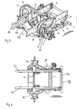
- Figure 1 is omitting the first and second side members, where the upper arm 3 and the lower arm 2 are connected, a vehicle axle with two independent suspensions according to the invention shown.
- An independent suspension according to the invention has a wheel carrier 1, which is designed as a steering knuckle.
- the wheel carrier 1 carries a fastener to which the vehicle wheel, not shown, can be attached.
- an upper wishbone 3 and a lower wishbone 2 are articulated via ball joints.
- a Spring 11 is arranged on the upper arm 3 .
- the spring 11 between the vehicle body not shown in Figure 1 and the upper arm 3 is effective. With its end facing away from the vehicle body, the spring 11 is supported on the upper wishbone third
- a vibration damper 12 is supported on the lower control arm 2.
- the vibration damper 12 is connected at its end facing away from the lower arm 2 at a fastener with the vehicle frame not shown in Figure 1.
- the connection of the vibration damper 12 with its end facing away from the lower arm 2 on a mounting bracket 45 which is connected to the first side member 34 is shown in Figure 3.
- the two independent suspensions are coupled to each other via a stabilizer 13, which serves for roll stabilization.
- the steering gear 15 is shown in Figure 1.
- the output of the steering gear 15 is a transverse to the direction of travel output shaft which is fixedly connected to the steering column lever 10.
- This steering column lever 10 acts via a ball joint 31 on the handlebar 9.
- the length of the pitman arm 10 varies depending on the vehicle model, so that always an optimal ratio between force and travel in the steering linkage can be adjusted.
- the steering linkage comprises the components steering column lever 10, handlebar 9 and tie rod elements 4, 5, 6, 7, 8.
- the wheel guide is based on the concept of a double wishbone axle.
- an air spring 11 assumes the function of the bodybuilder, which is positioned on the upper arm 3.
- Alternatively conceivable is the use of a steel coil spring instead of the air spring 11.
- the lower arm 2 and the upper arm 3 are connected by ball joints with the steering knuckle 1.
- the steering knuckle 1 receives both the wheel bearing and the caliper.
- the tie rod 4 is connected to the located on the steering knuckle 1 track lever by means of a ball joint 22.
- FIG. 3 shows the independent wheel suspensions of the wheels of an axle together with the first and second longitudinal carriers 34, 37 carrying the upper and lower control arms 2, 3.
- the first side members 34 are connected to each other via a cross pipe 44, whereby the rigidity of the frame structure is increased.
- On the first side member 34 of an independent suspension receiving consoles 34 are arranged, which receive the connection elements 17, 18 of the upper arm 3.
- the connection elements 17, 18 can be connected to the receiving brackets 34, a recess is provided in the web of the first longitudinal member 34 for each receiving element 17, 18, through which the receiving elements 17, 18 respectively reach.
- the upper wishbone 3 can be formed with longer legs than would be the case if the wishbone would not be connected in receiving consoles, but directly and directly to the web of the first longitudinal member 34.
- connection elements 38, 39, 40 fixed to the first side member 34.
- the connection elements 38, 39, 40 may be formed as pressed sheet metal parts in the form of open profiles or as formed from pressed sheet metal hollow sections. Seen on the right in the direction of travel independent wheel suspension can be clearly seen that the lower arm 2 is connected to the second side member 37, while the upper Wishbone 3 is connected to the first side member 34. On the first side rail 34 also brackets 35 and 45 are attached.
- the bracket 35 is formed as an arcuate receiving element and serves to support the air spring 11 relative to the vehicle body.
- a reinforcing element 36 can also be attached to the first side member 34. This is shown in FIG. 3.
- the reinforcing element 36 serves the additional support of the air spring 11 relative to the vehicle body.
- a deformation element 46 is arranged.
- This deformation element 46 can also be referred to as a crash element and serves primarily for energy absorption in the event of a crash.
- the deformation element 46 carries an underrun protection 47, which is intended to prevent accident partners in the event of a crash under the vehicle body (partner protection).
- the bracket 45 which is connected to the first side member 34, serves to support the vibration damper 12 with respect to the vehicle body.
- the vibration damper 12 is connected to the lower control arm 2 and is supported relative to the vehicle body via the bracket 45 directly on the first side member 34.
- the vehicle frame thus comprises two second longitudinal members 37, which are each assembled from two half-shells.
- the connection to the respective first longitudinal members 34 takes place via front, middle and rear attachment elements 38, 39, 40 and via the rear cross member 42.
- Another connecting element is formed by the front cross member 41 (see FIG. This construction can be called a double-frame construction.
- the first side members 34 form a primary frame, while the second side members form a secondary frame.
- the secondary frame includes the receptacles for the receiving elements of the lower arm 2, the stabilizer 13 and the bearings 28, 29 for the lever 7 and the guide lever 8 of the tie rods 4, 5, 6.
- the interaction of the primary vehicle frame and the secondary frame leads to an increase in the stiffness rates of the entire structure. Furthermore forms - as already stated - the front end of the secondary frame, the receptacle for the deformation elements 46 to which in turn the front underrun protection 47 is attached. Compared to conventional commercial vehicle designs introduced via the front underrun protection 47 impact loads are not forwarded directly behind the attachment of the deformation elements 46 in the upper (first) side member 34, but there is a force distribution instead. The force on impact is introduced via several connections (connecting elements 38, 39, 40) in the first side member. This leads to a balanced stress on the first side member 34.
- a particular advantage of the independent wheel suspension according to the invention is that it can be combined independently of the manufacturer with the ladder frame which is generally known in commercial vehicles.
- independent suspension according to the invention can be introduced via two different load paths in the frame structure by the separate arrangement of the spring 11 and the vibration damper 12, the forces to be absorbed by these elements.
- End stops can be placed both in the air spring 11 and the vibration damper 12 and can be individually adjusted so that there is an optimal distribution of impact forces.
- FIG. 4 the representation according to FIG. 3 is shown in plan view. Evident are seen in the direction of travel front cross member 41 and the rear cross member 42, which the second side members 37 together to form a frame connect. In connection with the illustration in FIG. 3, it can be seen clearly that a maximum space is available between the first longitudinal members 34.
- engine components or other components can be integrated.
Landscapes
- Engineering & Computer Science (AREA)
- Mechanical Engineering (AREA)
- Chemical & Material Sciences (AREA)
- Combustion & Propulsion (AREA)
- Transportation (AREA)
- Vehicle Body Suspensions (AREA)
Applications Claiming Priority (1)
| Application Number | Priority Date | Filing Date | Title |
|---|---|---|---|
| DE102006044151A DE102006044151A1 (de) | 2006-09-15 | 2006-09-15 | Einzelradaufhängung vom Doppelquerlenker-Typ |
Publications (2)
| Publication Number | Publication Date |
|---|---|
| EP1900554A1 true EP1900554A1 (fr) | 2008-03-19 |
| EP1900554B1 EP1900554B1 (fr) | 2011-11-02 |
Family
ID=38698195
Family Applications (1)
| Application Number | Title | Priority Date | Filing Date |
|---|---|---|---|
| EP07017369A Not-in-force EP1900554B1 (fr) | 2006-09-15 | 2007-09-05 | Suspension de roue unique de type à bras transversaux superposés |
Country Status (3)
| Country | Link |
|---|---|
| EP (1) | EP1900554B1 (fr) |
| AT (1) | ATE531540T1 (fr) |
| DE (1) | DE102006044151A1 (fr) |
Cited By (8)
| Publication number | Priority date | Publication date | Assignee | Title |
|---|---|---|---|---|
| CN107200062A (zh) * | 2017-06-16 | 2017-09-26 | 芜湖捷和科技有限公司 | 一种提高抗弯强度的转向桥 |
| WO2018039106A1 (fr) * | 2016-08-22 | 2018-03-01 | Stemco Products, Inc. | Suspension de remorque indépendante à double bras triangulaire |
| WO2019029909A1 (fr) * | 2017-08-08 | 2019-02-14 | Zf Friedrichshafen Ag | Suspension de roue |
| US10336379B2 (en) | 2016-05-09 | 2019-07-02 | Nikola Motor Company Llc | Vehicle rear suspension system |
| US10435075B2 (en) | 2016-05-06 | 2019-10-08 | Arvinmeritor Technology, Llc | Suspension module having a subframe assembly |
| CN111216500A (zh) * | 2020-01-10 | 2020-06-02 | 北京航天发射技术研究所 | 一体式双横臂独立悬架和油气弹簧安装支架 |
| US10981609B2 (en) | 2015-12-30 | 2021-04-20 | Nikola Corporation | Systems, methods, and devices for an automobile door or window |
| CN116198604A (zh) * | 2022-10-27 | 2023-06-02 | 阿尔特汽车技术股份有限公司 | 一种汽车平台 |
Families Citing this family (12)
| Publication number | Priority date | Publication date | Assignee | Title |
|---|---|---|---|---|
| DE102012019797A1 (de) * | 2012-10-10 | 2014-01-16 | Audi Ag | Radaufhängung für ein Vorderrad eines Kraftfahrzeugs |
| DE102013216029B4 (de) | 2013-08-13 | 2024-08-14 | Bayerische Motoren Werke Aktiengesellschaft | Lenkbare Vorderachse für Räder eines zweispurigen Kraftfahrzeugs und zweispuriges Kraftfahrzeug mit einer solchen Vorderachse |
| US11001129B2 (en) | 2015-12-30 | 2021-05-11 | Nikola Corporation | Cargo door for semi-truck |
| WO2017114420A1 (fr) * | 2015-12-31 | 2017-07-06 | Byd Company Limited | Véhicule et unité d'essieu moteur pour véhicule |
| RU169242U1 (ru) * | 2016-05-04 | 2017-03-13 | Общество С Ограниченной Ответственностью "Научно-Производственное Объединение "Ростар" | Узел передней независимой подвески транспортного средства |
| US10266025B2 (en) | 2016-05-06 | 2019-04-23 | Arvinmeritor Technology, Llc | Suspension module having an air spring pedestal |
| DE102017131165B4 (de) | 2017-12-22 | 2024-04-11 | Manitowoc Crane Group France Sas | Mobilkran-Fahrwerk |
| RU183897U1 (ru) * | 2018-05-29 | 2018-10-08 | Публичное акционерное общество "КАМАЗ" | Узел крепления элементов подвески |
| RU2684243C1 (ru) * | 2018-09-19 | 2019-04-04 | Акционерное общество "Брянский автомобильный завод" | Подвеска колеса транспортного средства |
| US10926596B2 (en) | 2019-02-28 | 2021-02-23 | Arvinmeritor Technology, Llc | Suspension system |
| US10814917B2 (en) | 2019-03-04 | 2020-10-27 | Arvinmeritor Technology, Llc | Assembly having a skid plate module |
| US10913321B2 (en) | 2019-03-04 | 2021-02-09 | Arvinmeritor Technology, Llc | Suspension system |
Citations (19)
| Publication number | Priority date | Publication date | Assignee | Title |
|---|---|---|---|---|
| DE3904723A1 (de) | 1988-02-17 | 1989-08-31 | Mazda Motor | Stuetzkonstruktion fuer die radaufhaengung eines fahrzeuges |
| US5149132A (en) * | 1991-02-04 | 1992-09-22 | A. O. Smith Corporation | Split rear truck frame |
| US5536035A (en) * | 1995-05-15 | 1996-07-16 | General Motors Corporation | Dual suspension shock tower |
| JPH0999867A (ja) * | 1995-10-03 | 1997-04-15 | Honda Motor Co Ltd | 自動車のサブフレーム支持構造 |
| DE19703951A1 (de) | 1996-02-22 | 1997-08-28 | Daihatsu Motor Co Ltd | Vorderteilkonstruktion einer Fahrzeugkarosserie |
| WO1998017486A1 (fr) * | 1996-10-23 | 1998-04-30 | Scania Cv Aktiebolag (Publ) | Suspension de roues pour vehicules |
| DE19847356A1 (de) * | 1997-10-15 | 1999-04-22 | Hyundai Motor Co Ltd | Vorderradaufhängung für ein Fahrzeug |
| DE19809209A1 (de) * | 1998-03-04 | 1999-09-09 | Man Nutzfahrzeuge Ag | Fahrgestell eines Frontlenker-Lastkraftwagen |
| US6149197A (en) * | 1997-06-06 | 2000-11-21 | Suzuki Motor Corporation | Structure of front body of automobiles |
| JP2001310756A (ja) * | 2000-04-28 | 2001-11-06 | Fuji Heavy Ind Ltd | 自動車の車体前部構造 |
| DE20022516U1 (de) | 2000-09-07 | 2001-11-08 | Thyssen Krupp Automotive AG, 44793 Bochum | Radaufhängung |
| DE10023112A1 (de) | 2000-05-11 | 2001-11-15 | Bayerische Motoren Werke Ag | Fahrzeugkarosserie |
| JP2003160060A (ja) * | 2001-11-22 | 2003-06-03 | Nissan Motor Co Ltd | 車体前部構造 |
| US20030184124A1 (en) * | 2002-04-02 | 2003-10-02 | Nissan Motor Co., Ltd. | Front vehicle frame structure |
| JP2004268680A (ja) * | 2003-03-06 | 2004-09-30 | Mitsubishi Automob Eng Co Ltd | 車体前部構造 |
| DE10321573A1 (de) * | 2003-05-14 | 2004-12-30 | Daimlerchrysler Ag | Crashstruktur für eine Kraftwagen-Rohbaustruktur |
| US20050134015A1 (en) * | 2000-12-28 | 2005-06-23 | Ziech James F. | Modular cast independent front suspension subframe |
| WO2005091699A1 (fr) * | 2004-03-25 | 2005-10-06 | Zf Friedrichshafen Ag | Suspension pour une roue orientable de vehicule |
| DE102004038487A1 (de) * | 2004-08-07 | 2006-03-16 | Man Nutzfahrzeuge Ag | Fahrgestell für ein Nutzfahrzeug |
Family Cites Families (5)
| Publication number | Priority date | Publication date | Assignee | Title |
|---|---|---|---|---|
| US5161818A (en) * | 1989-07-25 | 1992-11-10 | Kopieczek Anthony M J | Lateral compound torsion suspension |
| DE4336672A1 (de) * | 1993-10-27 | 1995-05-04 | Zahnradfabrik Friedrichshafen | Einzelradaufhängung |
| DE69429662T2 (de) * | 1994-10-13 | 2002-11-14 | Oshkosh Truck Corp., Oshkosh | Verbesserungen an unabhängigen Aufhängungen |
| DE10011417B4 (de) * | 2000-03-09 | 2006-01-26 | Daimlerchrysler Ag | Einzelradaufhängung mit radführenden Schräglenkern |
| DE102004003395A1 (de) * | 2004-01-23 | 2005-08-11 | Man Nutzfahrzeuge Aktiengesellschaft | Vorderachse mit Einzelradaufhängung und lenkbaren Rädern eines Nutzfahrzeugs |
-
2006
- 2006-09-15 DE DE102006044151A patent/DE102006044151A1/de not_active Ceased
-
2007
- 2007-09-05 EP EP07017369A patent/EP1900554B1/fr not_active Not-in-force
- 2007-09-05 AT AT07017369T patent/ATE531540T1/de active
Patent Citations (19)
| Publication number | Priority date | Publication date | Assignee | Title |
|---|---|---|---|---|
| DE3904723A1 (de) | 1988-02-17 | 1989-08-31 | Mazda Motor | Stuetzkonstruktion fuer die radaufhaengung eines fahrzeuges |
| US5149132A (en) * | 1991-02-04 | 1992-09-22 | A. O. Smith Corporation | Split rear truck frame |
| US5536035A (en) * | 1995-05-15 | 1996-07-16 | General Motors Corporation | Dual suspension shock tower |
| JPH0999867A (ja) * | 1995-10-03 | 1997-04-15 | Honda Motor Co Ltd | 自動車のサブフレーム支持構造 |
| DE19703951A1 (de) | 1996-02-22 | 1997-08-28 | Daihatsu Motor Co Ltd | Vorderteilkonstruktion einer Fahrzeugkarosserie |
| WO1998017486A1 (fr) * | 1996-10-23 | 1998-04-30 | Scania Cv Aktiebolag (Publ) | Suspension de roues pour vehicules |
| US6149197A (en) * | 1997-06-06 | 2000-11-21 | Suzuki Motor Corporation | Structure of front body of automobiles |
| DE19847356A1 (de) * | 1997-10-15 | 1999-04-22 | Hyundai Motor Co Ltd | Vorderradaufhängung für ein Fahrzeug |
| DE19809209A1 (de) * | 1998-03-04 | 1999-09-09 | Man Nutzfahrzeuge Ag | Fahrgestell eines Frontlenker-Lastkraftwagen |
| JP2001310756A (ja) * | 2000-04-28 | 2001-11-06 | Fuji Heavy Ind Ltd | 自動車の車体前部構造 |
| DE10023112A1 (de) | 2000-05-11 | 2001-11-15 | Bayerische Motoren Werke Ag | Fahrzeugkarosserie |
| DE20022516U1 (de) | 2000-09-07 | 2001-11-08 | Thyssen Krupp Automotive AG, 44793 Bochum | Radaufhängung |
| US20050134015A1 (en) * | 2000-12-28 | 2005-06-23 | Ziech James F. | Modular cast independent front suspension subframe |
| JP2003160060A (ja) * | 2001-11-22 | 2003-06-03 | Nissan Motor Co Ltd | 車体前部構造 |
| US20030184124A1 (en) * | 2002-04-02 | 2003-10-02 | Nissan Motor Co., Ltd. | Front vehicle frame structure |
| JP2004268680A (ja) * | 2003-03-06 | 2004-09-30 | Mitsubishi Automob Eng Co Ltd | 車体前部構造 |
| DE10321573A1 (de) * | 2003-05-14 | 2004-12-30 | Daimlerchrysler Ag | Crashstruktur für eine Kraftwagen-Rohbaustruktur |
| WO2005091699A1 (fr) * | 2004-03-25 | 2005-10-06 | Zf Friedrichshafen Ag | Suspension pour une roue orientable de vehicule |
| DE102004038487A1 (de) * | 2004-08-07 | 2006-03-16 | Man Nutzfahrzeuge Ag | Fahrgestell für ein Nutzfahrzeug |
Cited By (10)
| Publication number | Priority date | Publication date | Assignee | Title |
|---|---|---|---|---|
| US10981609B2 (en) | 2015-12-30 | 2021-04-20 | Nikola Corporation | Systems, methods, and devices for an automobile door or window |
| US11613312B2 (en) | 2015-12-30 | 2023-03-28 | Nikola Corporation | Systems, methods, and devices for an automobile door or window |
| US10435075B2 (en) | 2016-05-06 | 2019-10-08 | Arvinmeritor Technology, Llc | Suspension module having a subframe assembly |
| US10336379B2 (en) | 2016-05-09 | 2019-07-02 | Nikola Motor Company Llc | Vehicle rear suspension system |
| WO2018039106A1 (fr) * | 2016-08-22 | 2018-03-01 | Stemco Products, Inc. | Suspension de remorque indépendante à double bras triangulaire |
| CN107200062A (zh) * | 2017-06-16 | 2017-09-26 | 芜湖捷和科技有限公司 | 一种提高抗弯强度的转向桥 |
| WO2019029909A1 (fr) * | 2017-08-08 | 2019-02-14 | Zf Friedrichshafen Ag | Suspension de roue |
| US11167611B2 (en) | 2017-08-08 | 2021-11-09 | Zf Friedrichshafen Ag | Wheel suspension |
| CN111216500A (zh) * | 2020-01-10 | 2020-06-02 | 北京航天发射技术研究所 | 一体式双横臂独立悬架和油气弹簧安装支架 |
| CN116198604A (zh) * | 2022-10-27 | 2023-06-02 | 阿尔特汽车技术股份有限公司 | 一种汽车平台 |
Also Published As
| Publication number | Publication date |
|---|---|
| DE102006044151A1 (de) | 2008-03-27 |
| EP1900554B1 (fr) | 2011-11-02 |
| ATE531540T1 (de) | 2011-11-15 |
Similar Documents
| Publication | Publication Date | Title |
|---|---|---|
| EP1900554B1 (fr) | Suspension de roue unique de type à bras transversaux superposés | |
| DE102014205632B4 (de) | Einzelradaufhängung sowie Hinterachse mit Einzelradaufhängungen für ein Fahrzeug und entsprechend ausgestattetes Fahrzeug | |
| DE102004028161B4 (de) | Unterfahrschutz für Personenkraftfahrzeuge zur Anordnung unter Längsträgerniveau vor einem Hilfsrahmen oder Achsträger als zusätzliche Crashebene | |
| DE60125410T2 (de) | Fahrzeugaufhängungssystem | |
| EP2514616B1 (fr) | Suspension de roue pour un axe d'un véhicule automobile | |
| DE102013210338A1 (de) | Mehrlenkerhinterachse für ein Fahrzeug | |
| EP2922715B1 (fr) | Suspension de roue d'un véhicule automobile avec ensemble stabilisateur | |
| EP3922489B1 (fr) | Dispositif de ressort x pour une suspension de roue de véhicule automobile | |
| DE102008049761A1 (de) | Einzelradaufhängung für Fahrzeugrad und damit ausgerüstete Radachse | |
| EP1826100B1 (fr) | Montage composite pour un véhicule utilitaire à suspension pneumatique | |
| DE102017212638A1 (de) | Kraftfahrzeug | |
| EP1541393B1 (fr) | Essieu de torsion | |
| DE102014205635A1 (de) | Einzelradaufhängung sowie Hinterachse mit Einzelradaufhängungen für ein Fahrzeug und entsprechend ausgestattetes Fahrzeug | |
| EP1592570A1 (fr) | Suspension de roue destinee a des vehicules | |
| DE202014101432U1 (de) | Einzelradaufhängung sowie Hinterachse mit Einzelradaufhängungen für ein Fahrzeug und entsprechend ausgestattetes Fahrzeug | |
| EP0806310A2 (fr) | Suspension indépendante pour une roue directrice à suspension pneumatique d'un autobus ou camion | |
| WO2019037946A1 (fr) | Essieu de véhicule doté d'une unité d'entraînement montée de manière centrale | |
| EP1902873B1 (fr) | Faux-châssis avec suspension de roue indépendante et direction à crémaillère pour essieu avant | |
| DE102004058748B4 (de) | Mehrlenker-Hinterradaufhängung | |
| DE102017211277A1 (de) | Radaufhängung für ein Kraftfahrzeug | |
| EP0678442B1 (fr) | Suspension indépendante pour véhicules | |
| DE102011112387A1 (de) | Querstabilisator für ein Kraftfahrzeug | |
| DE102020113865A1 (de) | Radaufhängung | |
| DE102014200420B4 (de) | Einzelradaufhängung sowie Hinterachsmodul mit Einzelradaufhängungen für ein Fahrzeug und entsprechend ausgestattetes Fahrzeug | |
| WO2017137186A1 (fr) | Essieu semi-rigide directeur |
Legal Events
| Date | Code | Title | Description |
|---|---|---|---|
| PUAI | Public reference made under article 153(3) epc to a published international application that has entered the european phase |
Free format text: ORIGINAL CODE: 0009012 |
|
| AK | Designated contracting states |
Kind code of ref document: A1 Designated state(s): AT BE BG CH CY CZ DE DK EE ES FI FR GB GR HU IE IS IT LI LT LU LV MC MT NL PL PT RO SE SI SK TR |
|
| AX | Request for extension of the european patent |
Extension state: AL BA HR MK YU |
|
| 17P | Request for examination filed |
Effective date: 20080411 |
|
| 17Q | First examination report despatched |
Effective date: 20080613 |
|
| AKX | Designation fees paid |
Designated state(s): AT BE BG CH CY CZ DE DK EE ES FI FR GB GR HU IE IS IT LI LT LU LV MC MT NL PL PT RO SE SI SK TR |
|
| GRAP | Despatch of communication of intention to grant a patent |
Free format text: ORIGINAL CODE: EPIDOSNIGR1 |
|
| GRAS | Grant fee paid |
Free format text: ORIGINAL CODE: EPIDOSNIGR3 |
|
| GRAA | (expected) grant |
Free format text: ORIGINAL CODE: 0009210 |
|
| AK | Designated contracting states |
Kind code of ref document: B1 Designated state(s): AT BE BG CH CY CZ DE DK EE ES FI FR GB GR HU IE IS IT LI LT LU LV MC MT NL PL PT RO SE SI SK TR |
|
| REG | Reference to a national code |
Ref country code: GB Ref legal event code: FG4D Free format text: NOT ENGLISH |
|
| REG | Reference to a national code |
Ref country code: CH Ref legal event code: EP |
|
| REG | Reference to a national code |
Ref country code: IE Ref legal event code: FG4D |
|
| REG | Reference to a national code |
Ref country code: SE Ref legal event code: TRGR |
|
| REG | Reference to a national code |
Ref country code: DE Ref legal event code: R096 Ref document number: 502007008569 Country of ref document: DE Effective date: 20120202 |
|
| REG | Reference to a national code |
Ref country code: NL Ref legal event code: VDEP Effective date: 20111102 |
|
| LTIE | Lt: invalidation of european patent or patent extension |
Effective date: 20111102 |
|
| PG25 | Lapsed in a contracting state [announced via postgrant information from national office to epo] |
Ref country code: IS Free format text: LAPSE BECAUSE OF FAILURE TO SUBMIT A TRANSLATION OF THE DESCRIPTION OR TO PAY THE FEE WITHIN THE PRESCRIBED TIME-LIMIT Effective date: 20120302 Ref country code: LT Free format text: LAPSE BECAUSE OF FAILURE TO SUBMIT A TRANSLATION OF THE DESCRIPTION OR TO PAY THE FEE WITHIN THE PRESCRIBED TIME-LIMIT Effective date: 20111102 |
|
| PG25 | Lapsed in a contracting state [announced via postgrant information from national office to epo] |
Ref country code: PL Free format text: LAPSE BECAUSE OF FAILURE TO SUBMIT A TRANSLATION OF THE DESCRIPTION OR TO PAY THE FEE WITHIN THE PRESCRIBED TIME-LIMIT Effective date: 20111102 Ref country code: NL Free format text: LAPSE BECAUSE OF FAILURE TO SUBMIT A TRANSLATION OF THE DESCRIPTION OR TO PAY THE FEE WITHIN THE PRESCRIBED TIME-LIMIT Effective date: 20111102 Ref country code: PT Free format text: LAPSE BECAUSE OF FAILURE TO SUBMIT A TRANSLATION OF THE DESCRIPTION OR TO PAY THE FEE WITHIN THE PRESCRIBED TIME-LIMIT Effective date: 20120302 Ref country code: LV Free format text: LAPSE BECAUSE OF FAILURE TO SUBMIT A TRANSLATION OF THE DESCRIPTION OR TO PAY THE FEE WITHIN THE PRESCRIBED TIME-LIMIT Effective date: 20111102 Ref country code: SI Free format text: LAPSE BECAUSE OF FAILURE TO SUBMIT A TRANSLATION OF THE DESCRIPTION OR TO PAY THE FEE WITHIN THE PRESCRIBED TIME-LIMIT Effective date: 20111102 Ref country code: GR Free format text: LAPSE BECAUSE OF FAILURE TO SUBMIT A TRANSLATION OF THE DESCRIPTION OR TO PAY THE FEE WITHIN THE PRESCRIBED TIME-LIMIT Effective date: 20120203 |
|
| REG | Reference to a national code |
Ref country code: IE Ref legal event code: FD4D |
|
| PG25 | Lapsed in a contracting state [announced via postgrant information from national office to epo] |
Ref country code: CY Free format text: LAPSE BECAUSE OF FAILURE TO SUBMIT A TRANSLATION OF THE DESCRIPTION OR TO PAY THE FEE WITHIN THE PRESCRIBED TIME-LIMIT Effective date: 20111102 |
|
| PG25 | Lapsed in a contracting state [announced via postgrant information from national office to epo] |
Ref country code: EE Free format text: LAPSE BECAUSE OF FAILURE TO SUBMIT A TRANSLATION OF THE DESCRIPTION OR TO PAY THE FEE WITHIN THE PRESCRIBED TIME-LIMIT Effective date: 20111102 Ref country code: BG Free format text: LAPSE BECAUSE OF FAILURE TO SUBMIT A TRANSLATION OF THE DESCRIPTION OR TO PAY THE FEE WITHIN THE PRESCRIBED TIME-LIMIT Effective date: 20120202 Ref country code: SK Free format text: LAPSE BECAUSE OF FAILURE TO SUBMIT A TRANSLATION OF THE DESCRIPTION OR TO PAY THE FEE WITHIN THE PRESCRIBED TIME-LIMIT Effective date: 20111102 Ref country code: DK Free format text: LAPSE BECAUSE OF FAILURE TO SUBMIT A TRANSLATION OF THE DESCRIPTION OR TO PAY THE FEE WITHIN THE PRESCRIBED TIME-LIMIT Effective date: 20111102 Ref country code: CZ Free format text: LAPSE BECAUSE OF FAILURE TO SUBMIT A TRANSLATION OF THE DESCRIPTION OR TO PAY THE FEE WITHIN THE PRESCRIBED TIME-LIMIT Effective date: 20111102 Ref country code: IE Free format text: LAPSE BECAUSE OF FAILURE TO SUBMIT A TRANSLATION OF THE DESCRIPTION OR TO PAY THE FEE WITHIN THE PRESCRIBED TIME-LIMIT Effective date: 20111102 |
|
| PG25 | Lapsed in a contracting state [announced via postgrant information from national office to epo] |
Ref country code: RO Free format text: LAPSE BECAUSE OF FAILURE TO SUBMIT A TRANSLATION OF THE DESCRIPTION OR TO PAY THE FEE WITHIN THE PRESCRIBED TIME-LIMIT Effective date: 20111102 |
|
| PLBE | No opposition filed within time limit |
Free format text: ORIGINAL CODE: 0009261 |
|
| STAA | Information on the status of an ep patent application or granted ep patent |
Free format text: STATUS: NO OPPOSITION FILED WITHIN TIME LIMIT |
|
| 26N | No opposition filed |
Effective date: 20120803 |
|
| REG | Reference to a national code |
Ref country code: DE Ref legal event code: R097 Ref document number: 502007008569 Country of ref document: DE Effective date: 20120803 |
|
| BERE | Be: lapsed |
Owner name: THYSSENKRUPP AUTOMOTIVE SYSTEMS G.M.B.H. Effective date: 20120930 |
|
| PG25 | Lapsed in a contracting state [announced via postgrant information from national office to epo] |
Ref country code: MC Free format text: LAPSE BECAUSE OF NON-PAYMENT OF DUE FEES Effective date: 20120930 Ref country code: ES Free format text: LAPSE BECAUSE OF FAILURE TO SUBMIT A TRANSLATION OF THE DESCRIPTION OR TO PAY THE FEE WITHIN THE PRESCRIBED TIME-LIMIT Effective date: 20120213 |
|
| REG | Reference to a national code |
Ref country code: CH Ref legal event code: PL |
|
| PG25 | Lapsed in a contracting state [announced via postgrant information from national office to epo] |
Ref country code: FI Free format text: LAPSE BECAUSE OF FAILURE TO SUBMIT A TRANSLATION OF THE DESCRIPTION OR TO PAY THE FEE WITHIN THE PRESCRIBED TIME-LIMIT Effective date: 20111102 |
|
| PG25 | Lapsed in a contracting state [announced via postgrant information from national office to epo] |
Ref country code: LI Free format text: LAPSE BECAUSE OF NON-PAYMENT OF DUE FEES Effective date: 20120930 Ref country code: BE Free format text: LAPSE BECAUSE OF NON-PAYMENT OF DUE FEES Effective date: 20120930 Ref country code: CH Free format text: LAPSE BECAUSE OF NON-PAYMENT OF DUE FEES Effective date: 20120930 |
|
| REG | Reference to a national code |
Ref country code: AT Ref legal event code: MM01 Ref document number: 531540 Country of ref document: AT Kind code of ref document: T Effective date: 20120905 |
|
| PG25 | Lapsed in a contracting state [announced via postgrant information from national office to epo] |
Ref country code: MT Free format text: LAPSE BECAUSE OF FAILURE TO SUBMIT A TRANSLATION OF THE DESCRIPTION OR TO PAY THE FEE WITHIN THE PRESCRIBED TIME-LIMIT Effective date: 20111102 |
|
| PG25 | Lapsed in a contracting state [announced via postgrant information from national office to epo] |
Ref country code: AT Free format text: LAPSE BECAUSE OF NON-PAYMENT OF DUE FEES Effective date: 20120905 |
|
| PG25 | Lapsed in a contracting state [announced via postgrant information from national office to epo] |
Ref country code: TR Free format text: LAPSE BECAUSE OF FAILURE TO SUBMIT A TRANSLATION OF THE DESCRIPTION OR TO PAY THE FEE WITHIN THE PRESCRIBED TIME-LIMIT Effective date: 20111102 |
|
| PG25 | Lapsed in a contracting state [announced via postgrant information from national office to epo] |
Ref country code: LU Free format text: LAPSE BECAUSE OF NON-PAYMENT OF DUE FEES Effective date: 20120905 |
|
| PG25 | Lapsed in a contracting state [announced via postgrant information from national office to epo] |
Ref country code: HU Free format text: LAPSE BECAUSE OF FAILURE TO SUBMIT A TRANSLATION OF THE DESCRIPTION OR TO PAY THE FEE WITHIN THE PRESCRIBED TIME-LIMIT Effective date: 20070905 |
|
| REG | Reference to a national code |
Ref country code: FR Ref legal event code: PLFP Year of fee payment: 10 |
|
| REG | Reference to a national code |
Ref country code: FR Ref legal event code: PLFP Year of fee payment: 11 |
|
| REG | Reference to a national code |
Ref country code: FR Ref legal event code: PLFP Year of fee payment: 12 |
|
| PGFP | Annual fee paid to national office [announced via postgrant information from national office to epo] |
Ref country code: IT Payment date: 20210922 Year of fee payment: 15 Ref country code: FR Payment date: 20210921 Year of fee payment: 15 |
|
| PGFP | Annual fee paid to national office [announced via postgrant information from national office to epo] |
Ref country code: SE Payment date: 20210920 Year of fee payment: 15 Ref country code: DE Payment date: 20210920 Year of fee payment: 15 Ref country code: GB Payment date: 20210920 Year of fee payment: 15 |
|
| REG | Reference to a national code |
Ref country code: DE Ref legal event code: R119 Ref document number: 502007008569 Country of ref document: DE |
|
| REG | Reference to a national code |
Ref country code: SE Ref legal event code: EUG |
|
| GBPC | Gb: european patent ceased through non-payment of renewal fee |
Effective date: 20220905 |
|
| PG25 | Lapsed in a contracting state [announced via postgrant information from national office to epo] |
Ref country code: FR Free format text: LAPSE BECAUSE OF NON-PAYMENT OF DUE FEES Effective date: 20220930 Ref country code: DE Free format text: LAPSE BECAUSE OF NON-PAYMENT OF DUE FEES Effective date: 20230401 |
|
| PG25 | Lapsed in a contracting state [announced via postgrant information from national office to epo] |
Ref country code: SE Free format text: LAPSE BECAUSE OF NON-PAYMENT OF DUE FEES Effective date: 20220906 |
|
| PG25 | Lapsed in a contracting state [announced via postgrant information from national office to epo] |
Ref country code: IT Free format text: LAPSE BECAUSE OF NON-PAYMENT OF DUE FEES Effective date: 20220905 Ref country code: GB Free format text: LAPSE BECAUSE OF NON-PAYMENT OF DUE FEES Effective date: 20220905 |