EP1900570A1 - Lastengurt mit zugehöriger Halterung - Google Patents
Lastengurt mit zugehöriger Halterung Download PDFInfo
- Publication number
- EP1900570A1 EP1900570A1 EP07116166A EP07116166A EP1900570A1 EP 1900570 A1 EP1900570 A1 EP 1900570A1 EP 07116166 A EP07116166 A EP 07116166A EP 07116166 A EP07116166 A EP 07116166A EP 1900570 A1 EP1900570 A1 EP 1900570A1
- Authority
- EP
- European Patent Office
- Prior art keywords
- arms
- gripping
- container member
- strap
- clamp
- Prior art date
- Legal status (The legal status is an assumption and is not a legal conclusion. Google has not performed a legal analysis and makes no representation as to the accuracy of the status listed.)
- Granted
Links
- 239000011230 binding agent Substances 0.000 claims abstract description 19
- 230000007246 mechanism Effects 0.000 claims abstract description 14
- 230000027455 binding Effects 0.000 claims abstract 6
- 230000009471 action Effects 0.000 description 10
- 230000006872 improvement Effects 0.000 description 5
- 239000000463 material Substances 0.000 description 2
- 241000282887 Suidae Species 0.000 description 1
- 230000003466 anti-cipated effect Effects 0.000 description 1
- 238000005452 bending Methods 0.000 description 1
- 230000008901 benefit Effects 0.000 description 1
- 238000010276 construction Methods 0.000 description 1
- 230000001419 dependent effect Effects 0.000 description 1
- 230000000994 depressogenic effect Effects 0.000 description 1
- 230000009977 dual effect Effects 0.000 description 1
- 230000002708 enhancing effect Effects 0.000 description 1
- 239000002783 friction material Substances 0.000 description 1
- 238000009434 installation Methods 0.000 description 1
- 239000000203 mixture Substances 0.000 description 1
- 230000004048 modification Effects 0.000 description 1
- 238000012986 modification Methods 0.000 description 1
- 230000002265 prevention Effects 0.000 description 1
- 230000002441 reversible effect Effects 0.000 description 1
Images


Classifications
-
- B—PERFORMING OPERATIONS; TRANSPORTING
- B60—VEHICLES IN GENERAL
- B60P—VEHICLES ADAPTED FOR LOAD TRANSPORTATION OR TO TRANSPORT, TO CARRY, OR TO COMPRISE SPECIAL LOADS OR OBJECTS
- B60P7/00—Securing or covering of load on vehicles
- B60P7/06—Securing of load
- B60P7/08—Securing to the vehicle floor or sides
- B60P7/0823—Straps; Tighteners
-
- B—PERFORMING OPERATIONS; TRANSPORTING
- B60—VEHICLES IN GENERAL
- B60P—VEHICLES ADAPTED FOR LOAD TRANSPORTATION OR TO TRANSPORT, TO CARRY, OR TO COMPRISE SPECIAL LOADS OR OBJECTS
- B60P7/00—Securing or covering of load on vehicles
- B60P7/06—Securing of load
- B60P7/08—Securing to the vehicle floor or sides
- B60P7/0807—Attachment points
Definitions
- the present invention relates to a load binder for securing a load in a container used to transport goods between locations.
- Such containers may include truck boxes, railroad cars, cargo ships and the like. More specifically it relates to the latches or clamps used to position and secure a load retaining strap extended between side rails of a container.
- Two primary concerns of the design of a load binder include the time it takes for a worker(s) to apply and secure a load binder in place in the container, and the achieved securement of the load binder for prevention of load shifting, which may result in damage to the goods being shipped.
- a common load binder is a strap-type binder device having clamp members at each end.
- a cinch mechanism between the ends is released to allow sufficient strap length between the container sidewalls and enable engagement of the clamp members to the side boards or rails of opposing container walls.
- the cinch mechanism draws the strap tightly and in doing so produces clamping of the clamp members to the side boards.
- Sufficient cinching of the strap produces a clamping action to prevent slippage of the clamp members relative to the side rails of the container and thereby to secure the load against shifting.
- a current clamp member has a pair of S shaped rods.
- Each rod is configured to have a center segment that is pivotally secured in side by side relation.
- Arm segments of each rod extend angularly and oppositely from the center segments in a manner whereby closing of the arm segments at one side of the pivotal connection (the inner side) produces opening of the arm segments at the other side of the pivotal connection (the outer side).
- Depending gripping posts formed at the outer arm ends move closer and further away from the pivotal center to provide gripping of a container rail.
- the clamping mechanism as described above does produce a clamping action, that clamping or gripping action is not always adequate and there is a need to provide a clamp mechanism with enhanced gripping.
- the gripping or clamping action is provided by tightening (linear cinching) of the cinch strap, the linear or cinching force induces pivoting together of the arm segments at the inner end.
- the force vector that produces such pivoting diminishes as the arm segments are pivotally closed and the strap can reach a fully tightened condition prior to achieving a desired clamping action to the side boards.
- the present invention addresses and achieves the desired enhanced clamping action.
- improvements to the above current clamp may include replacing the dual center pivots for the arms with a single pivot, which can greatly enhance the gripping potential of the board clamp.
- a pair of opposing upper arms (oppositely angled or curved) may be commonly pivoted intermediate the arm ends to a common center pivot.
- gripping members may be provided at generally outer ends of an outer side, and strap-receiving members are provided at the outer ends of an inner side of opposing upper arms of the clamp.
- the common pivot increases the effective clamping force vector created by the linear pull when cinching or tightening of the strap takes place.
- a rotatably adjustable clamping pad may be provided.
- the clamping pad may be rotatably carried by the pivot or pivot shaft, and a pad surface may be provided on both sides of the pad such that the pad may rotate about the pivot shaft.
- the center of rotation of the pad about the pivot may be offset such that the pad surface on one side has a linear spacing relative to the gripping or clamping members greater than the other side (when reversibly rotated on the pivot shaft).
- the applied force of the cinching action diminishes as the gripping posts separate (the inner posts become closed or closer together).
- the reversible gripping pad may allow the gripping action to commence earlier in the pivoting action to enhance securement of the clamps to the rails.
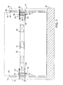
- FIG. 1 illustrates a back to front section view of a container and a load binder of the strap variety incorporating the present invention, and as shown, securing a load in the container;
- FIG. 2 is an enlarged view of the load binder only of FIG. 1;
- FIG. 3 is a bottom view of the load binder as seen from view lines 3-3 of FIG. 2;
- FIG. 4 is a view as taken on view lines 4-4 of FIG. 2;
- FIGS. 5A and 5B illustrates a clamp member only from side and bottom views respectively
- FIGS. 5C and 5D are similar to FIGS. 5A and 5B but with the clamping pads reversed i.e. for clamping a greater rail thickness;
- FIGS. 5E, 5F, and 5G are side, bottom, and top views respectively of the clamp members as shown in FIG. 5C but with the clamp member in a full open (non-clamping) condition;
- FIGS. 5H, 51, and 5J are side, bottom, and top views of the clamp members but showing the clamp members in a closed or clamping condition;
- FIGS. 6, 7, 8, 9A and 9B illustrate an improved cinching configuration.
- A/B means "A or B.”
- a and/or B means "(A), (B), or (A and B).
- the phrase “at least one of A, B and C” means “(A), (B), (C), (A and B), (A and C), (B and C) or (A, B and C).
- the phrase “(A) B” means "(B) or (A B)," that is, A is optional.
- Coupled may mean that two or more elements are in direct physical or electrical contact. However, “coupled” may also mean that two or more elements are not in direct contact with each other, but yet still cooperate or interact with each other.
- FIG. 1 illustrates perspective view of a board clamp in accordance with embodiments of the present invention.
- a container 10 having a floor or bed 12 may include for example spaced apart vertical side stanchions 14 having side boards or rails 16 coupled thereto.
- a load contained in the container is indicated by dash lines 18 (it is to be understood that container 10 can take any of numerous shapes, constructions and sizes as consistent with cargo hauling or transportation e.g. by land, sea, or rail (trucks, ships, or railroad cars)).
- a common feature for each, is the presence of opposing side rails such as will provide an exposed edge over which one or more clamp members 24 can be applied as illustrated in FIG. 1
- a load binder 22 includes a clamp member 24 at generally each end of the load binder and a strap 30 generally spanning the load-receiving width of the container 10.
- the clamp members may include sleeved or unsleeved gripping members 26 and gripping pads 28 that have been clamped onto the opposing rails 16 by tightening of the strap 30. Such tightening may be accomplished by any one of a variety of known cinching member 31.
- FIG. 2 illustrates a load binder 22 as illustrated in FIG. 1 but without the features of a container 10 or the cinching member 31.
- clamp member 24 may include an upper arm assembly 32 and a lower arm assembly 34.
- the upper arm assembly 32 includes overlapable upper arms 36 pivotally connected to pivot 38 intermediate its ends (see also FIGS. 5G and 5J).
- the lower arm assembly 34 may include overlapable arms 40 which may generally pivot about pivot 38 (see also FIGS. 5F and 51).
- some or all of the upper arms may be curved in nature relative to the pivot, as shown and described below, which may help in allowing for a more full range of motion and ability to avoid other components.
- the upper arms may have generally straight portions extending from the pivot to each end, or a mixture of straight and curved portions.
- the lower arms may also be curved as well as generally straight.
- the gripping members 26 depend generally from the outer ends of upper arms 36, and together with gripping pad 28 define entry 42 e.g. for mounting to a rail or board 16 as shown in FIG. 1.
- the inboard end of the clamp member 24 may include connecting members 46 that are disposed between the inboard ends of the paired upper and lower arms 36 and 40 as seen in FIG. 2.
- Strap 30 may include an end loop portion 48 that encircles the connecting members 46 at each end of the load binder 22.
- FIGS. 5A, 5B, 5C, and 5D Note that upper and lower arms 36 and 40 are similarly positioned in these figures. However, as compared to FIGS. 5A and 5B, the offset pad 28 in FIGS. 5C and 5D is rotated around pin 38 to place the thicker portion of the pad away from gripping members 26. This positioning may increase the entry 42 provided between the gripping members 26 and pad 28. Again, as explained herein, such reversal of the pad 28 enhances the ability of the clamp members to accommodate different thicknesses of boards or rails 20 (see FIG. 1).
- pads 28 may include pivot resist members 44.
- Pivot resist members 44 may include a protruding elastomeric knob that resists rotative movement of the pads 28 relative to the arms 36 and 40 and/or pivot 38. However, as desired by the installer, the knobs can be depressed or otherwise overcome to force rotation to the alternate positions i.e. as between FIGS. 5A and 5C.
- the installer may first determine a desirable rotative positioning of the gripping pads 28.
- the different sizes for entry 42 may be engineered to best accommodate the thicknesses of a 1" board or rail 16 versus a 2" board or rail 16.
- the entry 42 is desirably more closed with the pad 44 in a position similar to that shown in FIG. 5A and FIG. 5B.
- the setting of the pad 28 may be adjusted to widen the entry 42, similar to that illustrated in FIGs. 5C and 5D.
- FIGS. 5E, 5F, and 5G illustrate the boars/rail receiving position for the clamp member 24 in accordance with various embodiments of the present invention.
- the gripping members 26 are generally close to each other whereas the connecting members 46 and are generally more spaced apart. In this position the sleeved gripping members may be at or generally near the maximum spacing from pad 28. See spacing S 1 in FIG. 5F.
- FIGS. 5H, 51, and 5J illustrate a more full clamping position of the clamp member 24 in accordance with various embodiments.
- the connecting members will be brought towards each other while the gripping members are urged away from each other. Such movement may tend to cause a clamping of the board/rail between the gripping members and the pad.
- space S 2 in FIG. 5I as compared to space S 1 of FIG. 5F.
- FIG. 3 as compared to FIG. 5F illustrates the distance S in more of a closed configuration, which may be a clamped configuration depending on the thickness of the board/rail, connecting members 46 are more spaced apart.
- This relationship may be attributable in part to the relatively significant curvature provided to arms 36 (e.g. C-shaped), and may allow for the clamping action to increase as the clamping members 26 are further spaced apart. Further, such curvature may be considered a structural advantage, and thus allow for thinner materials to be used for the arms and still resist bending.
- the clamping force increases as the connecting members are brought closer together by the loop 48 of the strap being tightened and/or pulled generally linearly away from the clamp. The inward force applied to the closure of connecting members 46 may tend to decrease as the connecting members get closer together.
- connecting members 46 may be adapted to rotate about a substantially vertical axis, or may have a rotating sleeve that may help avoid sliding friction and wear as the loop 48 is opened and closed. Such may reduce wear of the strap at the inside of loop 48 and thereby extend the life of the strap 30.
- a lower friction material may be used for the connecting members and/or sleeves.
- the gripping members may also be rotatable and/or sleeved to resist damage and wear with respect to the boards/rails.
- FIGS. 6-8 The clamp mechanism or clamps 24 are illustrated but attached to a different type of cinching mechanism which may be referred to as a cam buckle 50.
- a cam buckle 50 typically a strap portion 52 is fixed to one end of the cam buckle and a one way releasable clutch indicated at 54 receives an opposing strap portion 56.
- This strap portion 56 is threaded through the buckle 50 and the free end of strap portion 56 is pulled through as indicated by arrow 62 in FIG. 8.
- cam style web securing devices, ratchet web securing devices, over-center buckle web securing devices, or any other common webbing/strap securing device may be used with the board clamp and/or the secondary leverage enhancing device.
- an improvement is provided for such load binder, in which various embodiments may include a reversing loop 60 secured to the strap portion 56.
- the strap portion 56 is first threaded through the buckle 50 and directed back onto itself to the reversing loop 60 as illustrated in FIG. 6.
- the strap portion may thus be reversed a second time and a cinching force is applied in the opposite direction to that of 62.
- Such may be referred to as double lining and can provides the installer with additional leverage i.e. a two inch pull of the strap end as double lined will produce substantially 1" of strap pulled through buckle 50 i.e. a 2 to 1 ratio of leverage and a substantial improvement in the generation of a desired force for tightening the strap.
- FIGS. 6, 7, and 8 illustrate a clamp mechanism as described for FIGS. 1-5, it will be appreciated that the double lining provided for buckle 50 via loop 60 may be applied to other forms of said gripping mechanism as illustrated in FIGS. 9A and 9B.
Landscapes
- Engineering & Computer Science (AREA)
- Transportation (AREA)
- Mechanical Engineering (AREA)
- Package Frames And Binding Bands (AREA)
- Load-Engaging Elements For Cranes (AREA)
- Packages (AREA)
Applications Claiming Priority (1)
| Application Number | Priority Date | Filing Date | Title |
|---|---|---|---|
| US11/532,057 US7594786B2 (en) | 2006-09-14 | 2006-09-14 | Load binder |
Publications (2)
| Publication Number | Publication Date |
|---|---|
| EP1900570A1 true EP1900570A1 (de) | 2008-03-19 |
| EP1900570B1 EP1900570B1 (de) | 2009-07-29 |
Family
ID=38606539
Family Applications (1)
| Application Number | Title | Priority Date | Filing Date |
|---|---|---|---|
| EP07116166A Not-in-force EP1900570B1 (de) | 2006-09-14 | 2007-09-11 | Lastengurt mit zugehöriger Halterung |
Country Status (5)
| Country | Link |
|---|---|
| US (1) | US7594786B2 (de) |
| EP (1) | EP1900570B1 (de) |
| AT (1) | ATE437773T1 (de) |
| DE (1) | DE602007001750D1 (de) |
| ES (1) | ES2328414T3 (de) |
Families Citing this family (1)
| Publication number | Priority date | Publication date | Assignee | Title |
|---|---|---|---|---|
| US11110849B1 (en) | 2019-03-07 | 2021-09-07 | Allen Alterie | Load securing device |
Citations (1)
| Publication number | Priority date | Publication date | Assignee | Title |
|---|---|---|---|---|
| DE20209231U1 (de) * | 2002-06-13 | 2002-09-12 | ANCRA Jungfalk GmbH & Co. KG, 78234 Engen | Verbindungsvorrichtung für einen Zurrstrang |
Family Cites Families (1)
| Publication number | Priority date | Publication date | Assignee | Title |
|---|---|---|---|---|
| EP0752342B1 (de) * | 1995-07-03 | 2000-05-17 | Spanset Inter Ag | Ladungssicherungsvorrichtung |
-
2006
- 2006-09-14 US US11/532,057 patent/US7594786B2/en not_active Expired - Fee Related
-
2007
- 2007-09-11 AT AT07116166T patent/ATE437773T1/de active
- 2007-09-11 ES ES07116166T patent/ES2328414T3/es active Active
- 2007-09-11 EP EP07116166A patent/EP1900570B1/de not_active Not-in-force
- 2007-09-11 DE DE602007001750T patent/DE602007001750D1/de active Active
Patent Citations (1)
| Publication number | Priority date | Publication date | Assignee | Title |
|---|---|---|---|---|
| DE20209231U1 (de) * | 2002-06-13 | 2002-09-12 | ANCRA Jungfalk GmbH & Co. KG, 78234 Engen | Verbindungsvorrichtung für einen Zurrstrang |
Also Published As
| Publication number | Publication date |
|---|---|
| EP1900570B1 (de) | 2009-07-29 |
| US20080069658A1 (en) | 2008-03-20 |
| DE602007001750D1 (de) | 2009-09-10 |
| ES2328414T3 (es) | 2009-11-12 |
| US7594786B2 (en) | 2009-09-29 |
| ATE437773T1 (de) | 2009-08-15 |
Similar Documents
| Publication | Publication Date | Title |
|---|---|---|
| US9266462B2 (en) | Buckle assembly for tie down strap | |
| AU2008247633B2 (en) | Tie down and tensioning system | |
| US5984379A (en) | Tarpaulin retention system | |
| US7207089B2 (en) | Bi-directional load securing ratchet method and apparatus | |
| US4796336A (en) | Two part buckle | |
| FI74435C (fi) | Laosanordning, speciellt foer laemmar till lastflak och dylikt. | |
| US9254778B2 (en) | Adjustable cam buckle | |
| US20080307612A1 (en) | Tie down tensioning device | |
| US5816185A (en) | Ratcheting means for quickly securing a cover over a boat and the method of using the same | |
| US7165294B2 (en) | Strap sack | |
| GB2082279A (en) | Strap tightener | |
| NO158450B (no) | Spenneanordning. | |
| US10814772B2 (en) | Rope tie down apparatus | |
| EP1900570B1 (de) | Lastengurt mit zugehöriger Halterung | |
| US4315350A (en) | Overcenter buckle | |
| US20110167600A1 (en) | Load binder | |
| US2825522A (en) | Boat-trailer tie-down mechanism | |
| US4921506A (en) | Clamp assembly | |
| KR200226124Y1 (ko) | 화물 묶음용 끈 조임장치 | |
| JP4095057B2 (ja) | 荷締器 | |
| JPH0121730Y2 (de) | ||
| JP4230042B2 (ja) | 荷締め装置 | |
| EP0771968A1 (de) | Hardbetätigte Seilspannvorrichtung | |
| CA2080168C (en) | Rope tightener with ropes | |
| JP2002031194A (ja) | 荷締具 |
Legal Events
| Date | Code | Title | Description |
|---|---|---|---|
| PUAI | Public reference made under article 153(3) epc to a published international application that has entered the european phase |
Free format text: ORIGINAL CODE: 0009012 |
|
| AK | Designated contracting states |
Kind code of ref document: A1 Designated state(s): AT BE BG CH CY CZ DE DK EE ES FI FR GB GR HU IE IS IT LI LT LU LV MC MT NL PL PT RO SE SI SK TR |
|
| AX | Request for extension of the european patent |
Extension state: AL BA HR MK YU |
|
| 17P | Request for examination filed |
Effective date: 20080319 |
|
| GRAP | Despatch of communication of intention to grant a patent |
Free format text: ORIGINAL CODE: EPIDOSNIGR1 |
|
| AKX | Designation fees paid |
Designated state(s): AT BE BG CH CY CZ DE DK EE ES FI FR GB GR HU IE IS IT LI LT LU LV MC MT NL PL PT RO SE SI SK TR |
|
| RIN1 | Information on inventor provided before grant (corrected) |
Inventor name: SCOTT, GARY M. |
|
| GRAS | Grant fee paid |
Free format text: ORIGINAL CODE: EPIDOSNIGR3 |
|
| GRAA | (expected) grant |
Free format text: ORIGINAL CODE: 0009210 |
|
| AK | Designated contracting states |
Kind code of ref document: B1 Designated state(s): AT BE BG CH CY CZ DE DK EE ES FI FR GB GR HU IE IS IT LI LT LU LV MC MT NL PL PT RO SE SI SK TR |
|
| REG | Reference to a national code |
Ref country code: GB Ref legal event code: FG4D |
|
| REG | Reference to a national code |
Ref country code: CH Ref legal event code: EP |
|
| REG | Reference to a national code |
Ref country code: IE Ref legal event code: FG4D |
|
| REF | Corresponds to: |
Ref document number: 602007001750 Country of ref document: DE Date of ref document: 20090910 Kind code of ref document: P |
|
| REG | Reference to a national code |
Ref country code: ES Ref legal event code: FG2A Ref document number: 2328414 Country of ref document: ES Kind code of ref document: T3 |
|
| REG | Reference to a national code |
Ref country code: SK Ref legal event code: T3 Ref document number: E 6221 Country of ref document: SK |
|
| PG25 | Lapsed in a contracting state [announced via postgrant information from national office to epo] |
Ref country code: SE Free format text: LAPSE BECAUSE OF FAILURE TO SUBMIT A TRANSLATION OF THE DESCRIPTION OR TO PAY THE FEE WITHIN THE PRESCRIBED TIME-LIMIT Effective date: 20090729 Ref country code: IS Free format text: LAPSE BECAUSE OF FAILURE TO SUBMIT A TRANSLATION OF THE DESCRIPTION OR TO PAY THE FEE WITHIN THE PRESCRIBED TIME-LIMIT Effective date: 20091129 Ref country code: LT Free format text: LAPSE BECAUSE OF FAILURE TO SUBMIT A TRANSLATION OF THE DESCRIPTION OR TO PAY THE FEE WITHIN THE PRESCRIBED TIME-LIMIT Effective date: 20090729 Ref country code: FI Free format text: LAPSE BECAUSE OF FAILURE TO SUBMIT A TRANSLATION OF THE DESCRIPTION OR TO PAY THE FEE WITHIN THE PRESCRIBED TIME-LIMIT Effective date: 20090729 |
|
| PG25 | Lapsed in a contracting state [announced via postgrant information from national office to epo] |
Ref country code: PL Free format text: LAPSE BECAUSE OF FAILURE TO SUBMIT A TRANSLATION OF THE DESCRIPTION OR TO PAY THE FEE WITHIN THE PRESCRIBED TIME-LIMIT Effective date: 20090729 Ref country code: LV Free format text: LAPSE BECAUSE OF FAILURE TO SUBMIT A TRANSLATION OF THE DESCRIPTION OR TO PAY THE FEE WITHIN THE PRESCRIBED TIME-LIMIT Effective date: 20090729 Ref country code: SI Free format text: LAPSE BECAUSE OF FAILURE TO SUBMIT A TRANSLATION OF THE DESCRIPTION OR TO PAY THE FEE WITHIN THE PRESCRIBED TIME-LIMIT Effective date: 20090729 |
|
| REG | Reference to a national code |
Ref country code: HU Ref legal event code: AG4A Ref document number: E006634 Country of ref document: HU |
|
| PG25 | Lapsed in a contracting state [announced via postgrant information from national office to epo] |
Ref country code: PT Free format text: LAPSE BECAUSE OF FAILURE TO SUBMIT A TRANSLATION OF THE DESCRIPTION OR TO PAY THE FEE WITHIN THE PRESCRIBED TIME-LIMIT Effective date: 20091129 Ref country code: BG Free format text: LAPSE BECAUSE OF FAILURE TO SUBMIT A TRANSLATION OF THE DESCRIPTION OR TO PAY THE FEE WITHIN THE PRESCRIBED TIME-LIMIT Effective date: 20091029 |
|
| RAP2 | Party data changed (patent owner data changed or rights of a patent transferred) |
Owner name: BURNS BROS., INC. |
|
| PG25 | Lapsed in a contracting state [announced via postgrant information from national office to epo] |
Ref country code: DK Free format text: LAPSE BECAUSE OF FAILURE TO SUBMIT A TRANSLATION OF THE DESCRIPTION OR TO PAY THE FEE WITHIN THE PRESCRIBED TIME-LIMIT Effective date: 20090729 Ref country code: EE Free format text: LAPSE BECAUSE OF FAILURE TO SUBMIT A TRANSLATION OF THE DESCRIPTION OR TO PAY THE FEE WITHIN THE PRESCRIBED TIME-LIMIT Effective date: 20090729 Ref country code: MC Free format text: LAPSE BECAUSE OF NON-PAYMENT OF DUE FEES Effective date: 20090930 Ref country code: RO Free format text: LAPSE BECAUSE OF FAILURE TO SUBMIT A TRANSLATION OF THE DESCRIPTION OR TO PAY THE FEE WITHIN THE PRESCRIBED TIME-LIMIT Effective date: 20090729 |
|
| PG25 | Lapsed in a contracting state [announced via postgrant information from national office to epo] |
Ref country code: BE Free format text: LAPSE BECAUSE OF FAILURE TO SUBMIT A TRANSLATION OF THE DESCRIPTION OR TO PAY THE FEE WITHIN THE PRESCRIBED TIME-LIMIT Effective date: 20090729 |
|
| PLBE | No opposition filed within time limit |
Free format text: ORIGINAL CODE: 0009261 |
|
| STAA | Information on the status of an ep patent application or granted ep patent |
Free format text: STATUS: NO OPPOSITION FILED WITHIN TIME LIMIT |
|
| REG | Reference to a national code |
Ref country code: HU Ref legal event code: HC9C Owner name: BURNS BROS., INC., US Free format text: FORMER OWNER(S): BURNS BROS., INC., US |
|
| 26N | No opposition filed |
Effective date: 20100503 |
|
| PG25 | Lapsed in a contracting state [announced via postgrant information from national office to epo] |
Ref country code: IE Free format text: LAPSE BECAUSE OF NON-PAYMENT OF DUE FEES Effective date: 20090911 |
|
| PG25 | Lapsed in a contracting state [announced via postgrant information from national office to epo] |
Ref country code: GR Free format text: LAPSE BECAUSE OF FAILURE TO SUBMIT A TRANSLATION OF THE DESCRIPTION OR TO PAY THE FEE WITHIN THE PRESCRIBED TIME-LIMIT Effective date: 20091030 |
|
| PGFP | Annual fee paid to national office [announced via postgrant information from national office to epo] |
Ref country code: HU Payment date: 20100830 Year of fee payment: 4 |
|
| REG | Reference to a national code |
Ref country code: FR Ref legal event code: CA |
|
| PGFP | Annual fee paid to national office [announced via postgrant information from national office to epo] |
Ref country code: CZ Payment date: 20100813 Year of fee payment: 4 Ref country code: SK Payment date: 20100816 Year of fee payment: 4 |
|
| PGFP | Annual fee paid to national office [announced via postgrant information from national office to epo] |
Ref country code: NL Payment date: 20100910 Year of fee payment: 4 |
|
| PG25 | Lapsed in a contracting state [announced via postgrant information from national office to epo] |
Ref country code: MT Free format text: LAPSE BECAUSE OF FAILURE TO SUBMIT A TRANSLATION OF THE DESCRIPTION OR TO PAY THE FEE WITHIN THE PRESCRIBED TIME-LIMIT Effective date: 20090729 Ref country code: LU Free format text: LAPSE BECAUSE OF NON-PAYMENT OF DUE FEES Effective date: 20090911 |
|
| PGFP | Annual fee paid to national office [announced via postgrant information from national office to epo] |
Ref country code: ES Payment date: 20101018 Year of fee payment: 4 |
|
| PG25 | Lapsed in a contracting state [announced via postgrant information from national office to epo] |
Ref country code: TR Free format text: LAPSE BECAUSE OF FAILURE TO SUBMIT A TRANSLATION OF THE DESCRIPTION OR TO PAY THE FEE WITHIN THE PRESCRIBED TIME-LIMIT Effective date: 20090729 |
|
| PG25 | Lapsed in a contracting state [announced via postgrant information from national office to epo] |
Ref country code: CY Free format text: LAPSE BECAUSE OF FAILURE TO SUBMIT A TRANSLATION OF THE DESCRIPTION OR TO PAY THE FEE WITHIN THE PRESCRIBED TIME-LIMIT Effective date: 20090729 |
|
| PGFP | Annual fee paid to national office [announced via postgrant information from national office to epo] |
Ref country code: IT Payment date: 20100930 Year of fee payment: 4 |
|
| REG | Reference to a national code |
Ref country code: NL Ref legal event code: V1 Effective date: 20120401 |
|
| PG25 | Lapsed in a contracting state [announced via postgrant information from national office to epo] |
Ref country code: CZ Free format text: LAPSE BECAUSE OF NON-PAYMENT OF DUE FEES Effective date: 20110911 |
|
| REG | Reference to a national code |
Ref country code: CH Ref legal event code: PL |
|
| GBPC | Gb: european patent ceased through non-payment of renewal fee |
Effective date: 20110911 |
|
| PG25 | Lapsed in a contracting state [announced via postgrant information from national office to epo] |
Ref country code: IT Free format text: LAPSE BECAUSE OF NON-PAYMENT OF DUE FEES Effective date: 20110911 |
|
| REG | Reference to a national code |
Ref country code: SK Ref legal event code: MM4A Ref document number: E 6221 Country of ref document: SK Effective date: 20110911 |
|
| REG | Reference to a national code |
Ref country code: DE Ref legal event code: R082 Ref document number: 602007001750 Country of ref document: DE Representative=s name: WILHELMS, KILIAN & PARTNER, DE |
|
| PG25 | Lapsed in a contracting state [announced via postgrant information from national office to epo] |
Ref country code: SK Free format text: LAPSE BECAUSE OF NON-PAYMENT OF DUE FEES Effective date: 20110911 Ref country code: HU Free format text: LAPSE BECAUSE OF NON-PAYMENT OF DUE FEES Effective date: 20110912 Ref country code: LI Free format text: LAPSE BECAUSE OF NON-PAYMENT OF DUE FEES Effective date: 20110930 Ref country code: NL Free format text: LAPSE BECAUSE OF NON-PAYMENT OF DUE FEES Effective date: 20120401 Ref country code: CH Free format text: LAPSE BECAUSE OF NON-PAYMENT OF DUE FEES Effective date: 20110930 |
|
| PG25 | Lapsed in a contracting state [announced via postgrant information from national office to epo] |
Ref country code: GB Free format text: LAPSE BECAUSE OF NON-PAYMENT OF DUE FEES Effective date: 20110911 |
|
| REG | Reference to a national code |
Ref country code: DE Ref legal event code: R082 Ref document number: 602007001750 Country of ref document: DE Representative=s name: KOTITSCHKE & HEURUNG PARTNERSCHAFT MBB, DE Effective date: 20120713 Ref country code: DE Ref legal event code: R081 Ref document number: 602007001750 Country of ref document: DE Owner name: PEERLESS CHAIN COMPANY, WINONA, US Free format text: FORMER OWNER: BURNS BROS., INC., LAKE OSWEGO, OREG., US Effective date: 20120713 Ref country code: DE Ref legal event code: R082 Ref document number: 602007001750 Country of ref document: DE Representative=s name: KOTITSCHKE & HEURUNG PARTNERSCHAFT MBB PATENT-, DE Effective date: 20120713 |
|
| REG | Reference to a national code |
Ref country code: FR Ref legal event code: TP Owner name: PEERLESS CHAIN COMPANY, US Effective date: 20121003 |
|
| REG | Reference to a national code |
Ref country code: AT Ref legal event code: PC Ref document number: 437773 Country of ref document: AT Kind code of ref document: T Owner name: PEERLESS CHAIN COMPANY, US Effective date: 20121102 |
|
| REG | Reference to a national code |
Ref country code: ES Ref legal event code: FD2A Effective date: 20130417 |
|
| PG25 | Lapsed in a contracting state [announced via postgrant information from national office to epo] |
Ref country code: ES Free format text: LAPSE BECAUSE OF NON-PAYMENT OF DUE FEES Effective date: 20110912 |
|
| PGFP | Annual fee paid to national office [announced via postgrant information from national office to epo] |
Ref country code: DE Payment date: 20130919 Year of fee payment: 7 Ref country code: AT Payment date: 20130911 Year of fee payment: 7 |
|
| PGFP | Annual fee paid to national office [announced via postgrant information from national office to epo] |
Ref country code: FR Payment date: 20130919 Year of fee payment: 7 |
|
| REG | Reference to a national code |
Ref country code: DE Ref legal event code: R082 Ref document number: 602007001750 Country of ref document: DE Representative=s name: KOTITSCHKE & HEURUNG PARTNERSCHAFT MBB, DE Ref country code: DE Ref legal event code: R082 Ref document number: 602007001750 Country of ref document: DE Representative=s name: KOTITSCHKE & HEURUNG PARTNERSCHAFT MBB PATENT-, DE |
|
| REG | Reference to a national code |
Ref country code: DE Ref legal event code: R119 Ref document number: 602007001750 Country of ref document: DE |
|
| REG | Reference to a national code |
Ref country code: AT Ref legal event code: MM01 Ref document number: 437773 Country of ref document: AT Kind code of ref document: T Effective date: 20140911 |
|
| REG | Reference to a national code |
Ref country code: DE Ref legal event code: R119 Ref document number: 602007001750 Country of ref document: DE Effective date: 20150401 |
|
| REG | Reference to a national code |
Ref country code: FR Ref legal event code: ST Effective date: 20150529 |
|
| PG25 | Lapsed in a contracting state [announced via postgrant information from national office to epo] |
Ref country code: DE Free format text: LAPSE BECAUSE OF NON-PAYMENT OF DUE FEES Effective date: 20150401 |
|
| PG25 | Lapsed in a contracting state [announced via postgrant information from national office to epo] |
Ref country code: FR Free format text: LAPSE BECAUSE OF NON-PAYMENT OF DUE FEES Effective date: 20140930 Ref country code: AT Free format text: LAPSE BECAUSE OF NON-PAYMENT OF DUE FEES Effective date: 20140911 |