EP1900663A2 - Bobineuse - Google Patents
Bobineuse Download PDFInfo
- Publication number
- EP1900663A2 EP1900663A2 EP07116417A EP07116417A EP1900663A2 EP 1900663 A2 EP1900663 A2 EP 1900663A2 EP 07116417 A EP07116417 A EP 07116417A EP 07116417 A EP07116417 A EP 07116417A EP 1900663 A2 EP1900663 A2 EP 1900663A2
- Authority
- EP
- European Patent Office
- Prior art keywords
- winding
- roll
- roller
- spring
- winding machine
- Prior art date
- Legal status (The legal status is an assumption and is not a legal conclusion. Google has not performed a legal analysis and makes no representation as to the accuracy of the status listed.)
- Granted
Links
- 238000004804 winding Methods 0.000 title claims abstract description 110
- 238000000034 method Methods 0.000 claims abstract description 9
- 239000000463 material Substances 0.000 claims abstract description 8
- 238000013016 damping Methods 0.000 claims description 25
- 238000005452 bending Methods 0.000 claims description 12
- 230000010355 oscillation Effects 0.000 claims description 3
- 230000003044 adaptive effect Effects 0.000 claims description 2
- 239000012530 fluid Substances 0.000 claims description 2
- 238000005096 rolling process Methods 0.000 abstract description 2
- 239000000725 suspension Substances 0.000 description 4
- 240000005860 Portulaca grandiflora Species 0.000 description 3
- 230000000694 effects Effects 0.000 description 3
- 210000003746 feather Anatomy 0.000 description 3
- 241001295925 Gegenes Species 0.000 description 2
- 238000013461 design Methods 0.000 description 2
- 229920001131 Pulp (paper) Polymers 0.000 description 1
- 230000001154 acute effect Effects 0.000 description 1
- 238000003490 calendering Methods 0.000 description 1
- 238000010276 construction Methods 0.000 description 1
- 230000003247 decreasing effect Effects 0.000 description 1
- 238000011161 development Methods 0.000 description 1
- 230000018109 developmental process Effects 0.000 description 1
- 238000010586 diagram Methods 0.000 description 1
- 230000005284 excitation Effects 0.000 description 1
- 238000007373 indentation Methods 0.000 description 1
- 238000005259 measurement Methods 0.000 description 1
- 230000021715 photosynthesis, light harvesting Effects 0.000 description 1
- 238000012545 processing Methods 0.000 description 1
- 230000001629 suppression Effects 0.000 description 1
Images

Classifications
-
- B—PERFORMING OPERATIONS; TRANSPORTING
- B65—CONVEYING; PACKING; STORING; HANDLING THIN OR FILAMENTARY MATERIAL
- B65H—HANDLING THIN OR FILAMENTARY MATERIAL, e.g. SHEETS, WEBS, CABLES
- B65H18/00—Winding webs
- B65H18/08—Web-winding mechanisms
- B65H18/14—Mechanisms in which power is applied to web roll, e.g. to effect continuous advancement of web
- B65H18/16—Mechanisms in which power is applied to web roll, e.g. to effect continuous advancement of web by friction roller
-
- B—PERFORMING OPERATIONS; TRANSPORTING
- B65—CONVEYING; PACKING; STORING; HANDLING THIN OR FILAMENTARY MATERIAL
- B65H—HANDLING THIN OR FILAMENTARY MATERIAL, e.g. SHEETS, WEBS, CABLES
- B65H18/00—Winding webs
- B65H18/08—Web-winding mechanisms
- B65H18/14—Mechanisms in which power is applied to web roll, e.g. to effect continuous advancement of web
- B65H18/20—Mechanisms in which power is applied to web roll, e.g. to effect continuous advancement of web the web roll being supported on two parallel rollers at least one of which is driven
-
- B—PERFORMING OPERATIONS; TRANSPORTING
- B65—CONVEYING; PACKING; STORING; HANDLING THIN OR FILAMENTARY MATERIAL
- B65H—HANDLING THIN OR FILAMENTARY MATERIAL, e.g. SHEETS, WEBS, CABLES
- B65H2301/00—Handling processes for sheets or webs
- B65H2301/40—Type of handling process
- B65H2301/41—Winding, unwinding
- B65H2301/414—Winding
- B65H2301/4148—Winding slitting
-
- B—PERFORMING OPERATIONS; TRANSPORTING
- B65—CONVEYING; PACKING; STORING; HANDLING THIN OR FILAMENTARY MATERIAL
- B65H—HANDLING THIN OR FILAMENTARY MATERIAL, e.g. SHEETS, WEBS, CABLES
- B65H2557/00—Means for control not provided for in groups B65H2551/00 - B65H2555/00
- B65H2557/60—Details of processes or procedures
- B65H2557/63—Optimisation, self-adjustment, self-learning processes or procedures, e.g. during start-up
-
- B—PERFORMING OPERATIONS; TRANSPORTING
- B65—CONVEYING; PACKING; STORING; HANDLING THIN OR FILAMENTARY MATERIAL
- B65H—HANDLING THIN OR FILAMENTARY MATERIAL, e.g. SHEETS, WEBS, CABLES
- B65H2601/00—Problem to be solved or advantage achieved
- B65H2601/50—Diminishing, minimizing or reducing
- B65H2601/52—Diminishing, minimizing or reducing entities relating to handling machine
- B65H2601/524—Vibration
- B65H2601/5244—Vibration by using electro-rheological fluid [ERF]
Definitions
- the invention relates to a winding machine for winding a material web, in particular a paper or board web, on at least one winding tube to a winding roll by means of at least one elastically mounted roller on which the winding roll when winding up or rests.
- Material webs must be wound up on shipping or finishing rolls before they can be shipped.
- reel cores usually winding cores are used, which are preferably made of cardboard.
- the finished rolls are produced by so-called mother or spool rolls, which are produced at the exit of a paper machine or after the calendering, unwound, cut in the longitudinal direction and then wound on each winding cores.
- mother or spool rolls which are produced at the exit of a paper machine or after the calendering, unwound, cut in the longitudinal direction and then wound on each winding cores.
- These cores are either on a support roller of a back-up roll winding machine or laterally on this, or the cores are in one of two support rollers of a double carrier roll winding machine formed winding bed.
- a back-up roll winding machine either only a single winding roll may be wound or a plurality of winding rolls each held in winding stations by individual tensioning devices, the tensioning devices alternating the winding rolls to both sides from a vertical axis passing through the center of the backing roll hold, wherein the connecting lines between the centers of the bobbins and the support roller are inclined in each case to both sides of the vertical at an acute angle or form a right angle with the vertical.
- the clamping heads and the winding tubes in the winding stations can also have different diameters.
- One from the DE-AS 23 18 351 known supporting device is characterized in that in all the essential parts and with respect to the characteristics of the same springs, the spring systems are arranged asymmetrically with respect to the plane passing through the winding roll axis vertical plane. In this way, the two support rollers associated lines of action are at an angle to each other, so that the vibrations also impinge on the respective suspension system in a different angle or at different locations. As a result, the suspension behavior of the suspension systems of the two support rollers is different, without that therefore the support roller suspension or its storage or the support rollers themselves would have to be designed differently or adjustable.
- this object is achieved in a winding machine of the type mentioned in that the deflection of the roller due to the changing during winding mass of the winding roll according to a pre-defined or adaptable by a adaptive or self-learning system spring stiffness per roll side as a function of the mass of the winding roll he follows.
- a support roller is optimally damped at their bearings when the bearing stiffness c L goes to zero. Then the support roller is mounted on each side only on a hydraulic cylinder in a linear guide or a lever. The hydraulic cylinder initiates the damping forces directly on the roll neck.
- this procedure is technically very complicated, since the position of the support roller must be kept exactly by a separate position control at each bearing point.
- the smallest misalignment of a carrier roll has a massive effect on the winding structure of the winding roll.
- the support rollers are still stored today on mechanically acting spring stiffness, for example on a flexible rocker, as in the above-mentioned DE 10 2005 024 266 A1 is disclosed.
- a technically sensible compromise between the technically complex position control with mechanically optimal damping on the one hand and a self-adjusting mechanical stiffness roller position - with increasing spring stiffness a decreasing damping capability is connected - thus represents a variable spring stiffness, as provided by the invention.
- the spring stiffness is controlled as a function of the paper roll weight so that the damping always works almost optimally.
- C L f m W .
- c L is the spring stiffness and m W the mass of the winding rolls.
- the spring effect can be integrated in the bearing of a roller, so that one can speak in this case instead of spring stiffness as well as bearing stiffness.
- the system comprises an actuator, a spring, in particular with a non-linear spring characteristic, a damper and a measuring device in order to be able to determine the position of the support rollers accurately.
- spring stiffness of the spring and / or the damping of the damper are variable.
- springs are used in the form of bending beams or as spiral springs.
- the damper comprises a damping cylinder, which is filled with an electrorheological or a magnetorheological fluid whose damping is changed by changing an applied electric or magnetic field.
- the winding machine is developed so that the at least one roller is equipped with a linear guide or another element, with the at least one roller is displaceable in the direction of the other roller.
- At least one of two rollers is fastened to a rocker, by means of which it is pivotable in the vertical direction or in the direction of the other carrier roller.
- the rocker is preferably infinitely adjustable in length.
- the invention also relates to a method for winding a material web, in particular a paper or board web, in a winding machine on a sleeve to a winding roll by means of at least one elastically mounted roller on which the winding roll on winding up or rests.
- the frequency of the oscillation problem ie the problematic resonance frequency
- the angular frequency ⁇ 2 * ⁇ * f can be preselected as constant.
- the tracking of the damping characteristic d is controlled as in the case of spring stiffness c L or controlled according to the mass m W of the winding roll.
- a mean value between the second highest contact frequency of the carrier roll and the winding roll and the carrier roll is set without the influence of the paper pulp.
- those frequencies are to be understood as meaning the frequencies at which the winding roll beats either in-phase or out-of-phase against the two winding rolls and thereby generates undesirable vibrations.
- the damping is preferably set to an intermediate value between the bending natural frequency of the roll and the second highest contact natural frequency of the roll to the winding rolls, or the damping is optimized for the strongest oscillation.
- the damping behavior can be optimized to the strongest of these vibrations.
- the damper setting is controlled as a function of the occurring problem frequencies ⁇ .
- the determination of the problem frequencies is carried out by a vibration measurement with subsequent harmonic analysis by Fourier transforms.
- the entire invention can be used in a double-winder winding machine, but also when only a single roller is used as a support roller for the cut longitudinally paper webs.
- the individual coils are supported alternately in an eleven o'clock or one o'clock position with respect to the support roller.
- there is a desire for optimal damping of the support roller which is realized by the use of a system according to the invention.
- the windings can also be located at other symmetrically opposite positions in the region of the two upper quadrants of the support roller.
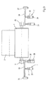
- a winding device formed by a double-winder winding machine has two support rollers 1, 2, at least one of which is driven.
- the support rollers 1, 2 form a roller bed, in which several adjacent bobbins 3 rest during winding on the support rollers 1, 2.
- a longitudinal cutting device (not shown), a material web, in particular a paper or board web, is cut into a plurality of individual webs before winding, which are then passed through the gap between the support rollers 1, 2 or laterally around the web Cloak one of the two support rollers 1, 2 are guided around in the roll bed, where they are wound up in aligned rows of sleeves 4.
- the support roller 1 is mounted on a positioning means 6 via a bearing 5, which comprises an actuator 7, a spring 8, a damper 9 and a measuring device 10. This generates according to the current position of the support roller 1, a signal that passes the measuring device 10 to the actuator 7, so that this according to a deviation between an actual position and a required target position of the support roller 1, a piston 11 of a hydraulic or pneumatic cylinder 12 actuated.
- an electromotive adjusting means such as a pneumatically operated bellows cylinder or a rolling diaphragm can be used.
- the piston 11 in turn presses on the spring 8, and this acts on the support roller 1 a.
- the damper 9 is a vibration energy dissipation element and includes, for example, a cylinder 13 filled with a gas.
- the gas is compressed by a punch 14 connected to the bearing 5. If, as a result of the vibrations of the support roller 1, the bearing 5 passes this to the punch 14, this compresses the gas, and a part of the vibration energy is converted into heat. It is understood that the vibrational energy can be derived in other ways from the system, for example by electrical eddy currents.
- the support roller 2 is mounted on a bearing 15 which, like the bearing 5 of the support roller 1 is mounted.
- the spring stiffness of the spring 8 can be changed.
- a linear guide 16 is arranged on the bearing 5 of the support roller 1, by which the height position and / or the horizontal position of the bearing 5 and thus the position of the support roller 1 with respect to the support roller 2 and in Reference to the winding 3 can be adjusted.
- the support roller 2 is mounted on a rocker 17 pivotally mounted about a pivot point 18 to their position with respect to the support roller 1 and the coil. 3 to be able to change.
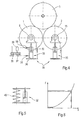
- the actuator 7 comprises on both sides of the shaft of the support roller 1 springs designed as bending beams 19, 20 for elastically supporting the support roller 1, via which bearings 5, 25
- Piston 21, 22 of cylinders 23, 24 act.
- the bending beam 19, 20 press in turn against the bearings 5, 25 of the support rollers 1, 2 and are mounted in brackets 26, 27.
- the rigidity of the bending beams 19, 20 can be changed by changing the position of the cylinders 23, 24 in the direction of the axes of the bending springs 19, 20.
- a damper 28, 29 is also provided in each case.
- a measuring device 30 for determining the position of the support roller 1 is provided.
- the support rollers 1, 2 are mounted on positioning means 31, each comprising a hydraulic cylinder 32 and 33, respectively.
- the cylinder 32 has an oil column 34 whose length is adjustable via a valve 35 from an oil reservoir.
- Throttles 38, 39 are preferably present, via which the speed with which the oil or the air can escape from the interior of the cylinder 32 is set.
- the cylinder 33 is preferably constructed in the same way as illustrated by the example of the cylinder 32.
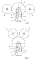
- a back-up roll winding machine ( Figure 7) is shown with a back-up roll 41 against which two bobbins 42, 43 are respectively supported in the nine o'clock position and the three o'clock position.
- the winding rollers 42, 43 are supported by (not shown here) supporting devices and pressed against the jacket of the support roller 41.
- the support roller 41 is mounted on a positioning means 45 via a bearing 44, which, like the positioning means 6, comprises an actuator 46, a spring 47, a damper 48 and a measuring device 49.
- a setting or control device can be arranged in the backup roll winding machine to adjust the position of the positioning means 45 according to the weight of the winding rolls 40, 41 changing during the winding operation ,
- FIG. 8 another embodiment of a backup roll winding machine is shown, are employed in the winding rollers 50, 51 against a support roller 52.
- a positioning means having the same construction as the positioning means 45 of FIG. 7 and therefore designated by the same reference numerals.
Landscapes
- Winding Of Webs (AREA)
- Replacement Of Web Rolls (AREA)
Applications Claiming Priority (1)
| Application Number | Priority Date | Filing Date | Title |
|---|---|---|---|
| DE102006043639A DE102006043639A1 (de) | 2006-09-18 | 2006-09-18 | Wickelmaschine |
Publications (3)
| Publication Number | Publication Date |
|---|---|
| EP1900663A2 true EP1900663A2 (fr) | 2008-03-19 |
| EP1900663A3 EP1900663A3 (fr) | 2008-12-24 |
| EP1900663B1 EP1900663B1 (fr) | 2011-04-20 |
Family
ID=38754762
Family Applications (1)
| Application Number | Title | Priority Date | Filing Date |
|---|---|---|---|
| EP07116417A Not-in-force EP1900663B1 (fr) | 2006-09-18 | 2007-09-14 | Procédé d'enroulage d'une bande |
Country Status (3)
| Country | Link |
|---|---|
| EP (1) | EP1900663B1 (fr) |
| AT (1) | ATE506306T1 (fr) |
| DE (2) | DE102006043639A1 (fr) |
Cited By (6)
| Publication number | Priority date | Publication date | Assignee | Title |
|---|---|---|---|---|
| EP2135828A3 (fr) * | 2008-06-18 | 2010-12-08 | Metso Paper, Inc. | Appareil d'enroulement de toile fibreuse et procédé d'enroulement de toile fibreuse |
| EP2341023A3 (fr) * | 2009-12-29 | 2012-03-28 | Voith Patent GmbH | Dispositif d'enroulement à rouleaux et procédé destiné à enrouler une bande de matériau |
| CN108673952A (zh) * | 2018-08-01 | 2018-10-19 | 浙江环龙机器有限公司 | 一种芯棒调节装置 |
| CN111115327A (zh) * | 2019-12-25 | 2020-05-08 | 晋江圣翔机械有限公司 | 一种剖布机的出料控制系统 |
| CN115893059A (zh) * | 2022-11-25 | 2023-04-04 | 齐齐哈尔建华机械有限公司 | 一种宣传弹用宣传纸阵地装配的半自动卷纸工装 |
| CN118771040A (zh) * | 2024-09-11 | 2024-10-15 | 常州丰兴诚环保科技有限公司 | 一种加厚预浸料成品收卷装置 |
Families Citing this family (2)
| Publication number | Priority date | Publication date | Assignee | Title |
|---|---|---|---|---|
| DE102011112032A1 (de) * | 2011-08-31 | 2013-02-28 | Andritz Küsters Gmbh | Verfahren zum Aufwickeln von geschnitten zugeführtem Wickelgut und Doppeltragwalzenroller |
| CN117864535A (zh) * | 2023-03-14 | 2024-04-12 | 马鞍山森奎科技有限公司 | 一种薄膜加工用的薄膜收缩机 |
Citations (9)
| Publication number | Priority date | Publication date | Assignee | Title |
|---|---|---|---|---|
| DE7121923U (de) | 1971-06-05 | 1972-11-30 | J Voith Gmbh | Trageinrichtung fuer aus bahnen aufgewickelte rollen |
| DE2318351B1 (de) | 1973-04-12 | 1974-07-25 | J.M. Voith Gmbh, 7920 Heidenheim | Trageinrichtung für eine Wickelrolle |
| DE7305837U (de) | 1973-02-16 | 1974-10-10 | Voith J Gmbh | Trageinrichtung fuer aus bahnen aufgewickelte rollen |
| EP0792245B1 (fr) | 1995-11-01 | 1999-06-09 | Valmet Corporation | Procede de bobinage |
| DE20013319U1 (de) | 2000-08-02 | 2000-09-28 | Voith Sulzer Papiertechnik Patent GmbH, 89522 Heidenheim | Bahnanfangsbefestigung |
| EP0829438B1 (fr) | 1994-05-26 | 2002-04-03 | Metso Paper, Inc. | Méthode pour enrouler une Bande |
| EP1260470A2 (fr) | 2001-05-23 | 2002-11-27 | Voith Paper Jagenberg GmbH | Méthode et dispositif pour l'amortissement actif de vibrations dans des enrouleuses |
| DE102004062890A1 (de) | 2004-01-06 | 2005-10-13 | Eras Gmbh | Rollenwickeleinrichtung |
| DE102005024266A1 (de) | 2005-05-27 | 2006-11-30 | Voith Patent Gmbh | Rollenwickeleinrichtung |
Family Cites Families (1)
| Publication number | Priority date | Publication date | Assignee | Title |
|---|---|---|---|---|
| DE102004000033A1 (de) * | 2004-10-21 | 2006-04-27 | Voith Paper Patent Gmbh | Wickelmaschine |
-
2006
- 2006-09-18 DE DE102006043639A patent/DE102006043639A1/de not_active Withdrawn
-
2007
- 2007-09-14 EP EP07116417A patent/EP1900663B1/fr not_active Not-in-force
- 2007-09-14 DE DE502007006980T patent/DE502007006980D1/de active Active
- 2007-09-14 AT AT07116417T patent/ATE506306T1/de active
Patent Citations (9)
| Publication number | Priority date | Publication date | Assignee | Title |
|---|---|---|---|---|
| DE7121923U (de) | 1971-06-05 | 1972-11-30 | J Voith Gmbh | Trageinrichtung fuer aus bahnen aufgewickelte rollen |
| DE7305837U (de) | 1973-02-16 | 1974-10-10 | Voith J Gmbh | Trageinrichtung fuer aus bahnen aufgewickelte rollen |
| DE2318351B1 (de) | 1973-04-12 | 1974-07-25 | J.M. Voith Gmbh, 7920 Heidenheim | Trageinrichtung für eine Wickelrolle |
| EP0829438B1 (fr) | 1994-05-26 | 2002-04-03 | Metso Paper, Inc. | Méthode pour enrouler une Bande |
| EP0792245B1 (fr) | 1995-11-01 | 1999-06-09 | Valmet Corporation | Procede de bobinage |
| DE20013319U1 (de) | 2000-08-02 | 2000-09-28 | Voith Sulzer Papiertechnik Patent GmbH, 89522 Heidenheim | Bahnanfangsbefestigung |
| EP1260470A2 (fr) | 2001-05-23 | 2002-11-27 | Voith Paper Jagenberg GmbH | Méthode et dispositif pour l'amortissement actif de vibrations dans des enrouleuses |
| DE102004062890A1 (de) | 2004-01-06 | 2005-10-13 | Eras Gmbh | Rollenwickeleinrichtung |
| DE102005024266A1 (de) | 2005-05-27 | 2006-11-30 | Voith Patent Gmbh | Rollenwickeleinrichtung |
Cited By (8)
| Publication number | Priority date | Publication date | Assignee | Title |
|---|---|---|---|---|
| EP2135828A3 (fr) * | 2008-06-18 | 2010-12-08 | Metso Paper, Inc. | Appareil d'enroulement de toile fibreuse et procédé d'enroulement de toile fibreuse |
| EP2341023A3 (fr) * | 2009-12-29 | 2012-03-28 | Voith Patent GmbH | Dispositif d'enroulement à rouleaux et procédé destiné à enrouler une bande de matériau |
| CN108673952A (zh) * | 2018-08-01 | 2018-10-19 | 浙江环龙机器有限公司 | 一种芯棒调节装置 |
| CN108673952B (zh) * | 2018-08-01 | 2024-02-13 | 山东品圣纸管有限公司 | 一种芯棒调节装置 |
| CN111115327A (zh) * | 2019-12-25 | 2020-05-08 | 晋江圣翔机械有限公司 | 一种剖布机的出料控制系统 |
| CN111115327B (zh) * | 2019-12-25 | 2021-07-27 | 晋江圣翔机械有限公司 | 一种剖布机的出料控制系统 |
| CN115893059A (zh) * | 2022-11-25 | 2023-04-04 | 齐齐哈尔建华机械有限公司 | 一种宣传弹用宣传纸阵地装配的半自动卷纸工装 |
| CN118771040A (zh) * | 2024-09-11 | 2024-10-15 | 常州丰兴诚环保科技有限公司 | 一种加厚预浸料成品收卷装置 |
Also Published As
| Publication number | Publication date |
|---|---|
| DE502007006980D1 (de) | 2011-06-01 |
| EP1900663A3 (fr) | 2008-12-24 |
| EP1900663B1 (fr) | 2011-04-20 |
| ATE506306T1 (de) | 2011-05-15 |
| DE102006043639A1 (de) | 2008-03-27 |
Similar Documents
| Publication | Publication Date | Title |
|---|---|---|
| EP1900663B1 (fr) | Procédé d'enroulage d'une bande | |
| EP1260470B1 (fr) | Méthode et dispositif pour l'amortissement actif de vibrations dans des enrouleuses | |
| EP0819638A2 (fr) | Procédé et dispositif pour enrouler une bande de papier en un rouleau avec amortisseur actif de vibrations | |
| WO2003064763A1 (fr) | Procede et dispositif pour reduire des vibrations sur des composants en rotation | |
| DE112007000826T5 (de) | Verfahren zur Dämpfung von Schwingungen in Aufwicklern | |
| EP1739040B1 (fr) | Enrouleuse | |
| DE102005000052A1 (de) | Wickelmaschine | |
| EP1650148A2 (fr) | Machine d'enroulement | |
| EP1900662A2 (fr) | Bobineuse | |
| DE102006043628A1 (de) | Wickelmaschine mit dämpfungsgeregelten Druckwalzen | |
| AT506025B1 (de) | Verfahren und vorrichtung zur dämpfung von walzenschwingungen | |
| DE7305837U (de) | Trageinrichtung fuer aus bahnen aufgewickelte rollen | |
| EP1683749B1 (fr) | Bobineuse avec cylindres porteurs | |
| EP1790600B1 (fr) | Enrouleuse | |
| EP2502860B1 (fr) | Dispositif d'enroulement d'une bande de matériau | |
| DE102009055352A1 (de) | Rollenwickelvorrichtung und Verfahren zum Aufwickeln einer Materialbahn | |
| AT509265B1 (de) | Wickelpartie für einen rollenschneider einer faserbahn und verfahren zum modernisieren einer wickelpartie für einen rollenschneider einer faserbahn | |
| EP1857389B1 (fr) | Bobineuse à deux rouleaux de support destinée à l'embobinage d'une bande de matériau | |
| DE102006023831A1 (de) | Rollenwickeleinrichtung | |
| DE102008053467A1 (de) | Mit einem Druckwalzenbalken und einer Druckwalze versehener Aufroller vom Tragwalzentyp und Verfahren | |
| EP1764327B1 (fr) | Dispositif d'enroulement | |
| EP2502861B1 (fr) | Dispositif et procédé d'enroulement d'une bande de matériau | |
| DE112011103576B4 (de) | Walzenstützanordnung einer Faserbahnmaschine und Teilbahnwickler einer Faserbahnrollenschneidmaschine | |
| EP2080931A2 (fr) | Agencement de stockage isolé activement | |
| DE202006004449U1 (de) | Rollenwickelvorrichtung zum Aufwickeln einer Materialbahn |
Legal Events
| Date | Code | Title | Description |
|---|---|---|---|
| PUAI | Public reference made under article 153(3) epc to a published international application that has entered the european phase |
Free format text: ORIGINAL CODE: 0009012 |
|
| AK | Designated contracting states |
Kind code of ref document: A2 Designated state(s): AT BE BG CH CY CZ DE DK EE ES FI FR GB GR HU IE IS IT LI LT LU LV MC MT NL PL PT RO SE SI SK TR |
|
| AX | Request for extension of the european patent |
Extension state: AL BA HR MK YU |
|
| PUAL | Search report despatched |
Free format text: ORIGINAL CODE: 0009013 |
|
| AK | Designated contracting states |
Kind code of ref document: A3 Designated state(s): AT BE BG CH CY CZ DE DK EE ES FI FR GB GR HU IE IS IT LI LT LU LV MC MT NL PL PT RO SE SI SK TR |
|
| AX | Request for extension of the european patent |
Extension state: AL BA HR MK RS |
|
| RIC1 | Information provided on ipc code assigned before grant |
Ipc: B65H 18/02 20060101ALI20081118BHEP Ipc: B65H 18/20 20060101AFI20071210BHEP |
|
| 17P | Request for examination filed |
Effective date: 20090624 |
|
| AKX | Designation fees paid |
Designated state(s): AT DE FI IT SE |
|
| 17Q | First examination report despatched |
Effective date: 20091001 |
|
| GRAP | Despatch of communication of intention to grant a patent |
Free format text: ORIGINAL CODE: EPIDOSNIGR1 |
|
| RIC1 | Information provided on ipc code assigned before grant |
Ipc: B65H 18/14 20060101ALI20101011BHEP Ipc: B65H 18/02 20060101AFI20101011BHEP |
|
| RTI1 | Title (correction) |
Free format text: METHOD FOR WINDING A WEB MATERIAL |
|
| GRAS | Grant fee paid |
Free format text: ORIGINAL CODE: EPIDOSNIGR3 |
|
| GRAA | (expected) grant |
Free format text: ORIGINAL CODE: 0009210 |
|
| AK | Designated contracting states |
Kind code of ref document: B1 Designated state(s): AT DE FI IT SE |
|
| REF | Corresponds to: |
Ref document number: 502007006980 Country of ref document: DE Date of ref document: 20110601 Kind code of ref document: P |
|
| REG | Reference to a national code |
Ref country code: DE Ref legal event code: R096 Ref document number: 502007006980 Country of ref document: DE Effective date: 20110601 |
|
| REG | Reference to a national code |
Ref country code: SE Ref legal event code: TRGR |
|
| PGFP | Annual fee paid to national office [announced via postgrant information from national office to epo] |
Ref country code: SE Payment date: 20110923 Year of fee payment: 5 |
|
| PLBE | No opposition filed within time limit |
Free format text: ORIGINAL CODE: 0009261 |
|
| STAA | Information on the status of an ep patent application or granted ep patent |
Free format text: STATUS: NO OPPOSITION FILED WITHIN TIME LIMIT |
|
| 26N | No opposition filed |
Effective date: 20120123 |
|
| REG | Reference to a national code |
Ref country code: DE Ref legal event code: R097 Ref document number: 502007006980 Country of ref document: DE Effective date: 20120123 |
|
| PG25 | Lapsed in a contracting state [announced via postgrant information from national office to epo] |
Ref country code: SE Free format text: LAPSE BECAUSE OF NON-PAYMENT OF DUE FEES Effective date: 20120915 |
|
| REG | Reference to a national code |
Ref country code: SE Ref legal event code: EUG |
|
| PGFP | Annual fee paid to national office [announced via postgrant information from national office to epo] |
Ref country code: AT Payment date: 20130911 Year of fee payment: 7 Ref country code: DE Payment date: 20130919 Year of fee payment: 7 Ref country code: FI Payment date: 20130911 Year of fee payment: 7 |
|
| PGFP | Annual fee paid to national office [announced via postgrant information from national office to epo] |
Ref country code: IT Payment date: 20130930 Year of fee payment: 7 |
|
| REG | Reference to a national code |
Ref country code: DE Ref legal event code: R119 Ref document number: 502007006980 Country of ref document: DE |
|
| PG25 | Lapsed in a contracting state [announced via postgrant information from national office to epo] |
Ref country code: FI Free format text: LAPSE BECAUSE OF NON-PAYMENT OF DUE FEES Effective date: 20140914 |
|
| REG | Reference to a national code |
Ref country code: AT Ref legal event code: MM01 Ref document number: 506306 Country of ref document: AT Kind code of ref document: T Effective date: 20140914 |
|
| REG | Reference to a national code |
Ref country code: DE Ref legal event code: R119 Ref document number: 502007006980 Country of ref document: DE Effective date: 20150401 |
|
| PG25 | Lapsed in a contracting state [announced via postgrant information from national office to epo] |
Ref country code: DE Free format text: LAPSE BECAUSE OF NON-PAYMENT OF DUE FEES Effective date: 20150401 |
|
| PG25 | Lapsed in a contracting state [announced via postgrant information from national office to epo] |
Ref country code: AT Free format text: LAPSE BECAUSE OF NON-PAYMENT OF DUE FEES Effective date: 20140914 Ref country code: IT Free format text: LAPSE BECAUSE OF NON-PAYMENT OF DUE FEES Effective date: 20140914 |