EP1900864B1 - Procédé et dispositif pour le mercerisage en continu des fils textiles - Google Patents
Procédé et dispositif pour le mercerisage en continu des fils textiles Download PDFInfo
- Publication number
- EP1900864B1 EP1900864B1 EP20070115878 EP07115878A EP1900864B1 EP 1900864 B1 EP1900864 B1 EP 1900864B1 EP 20070115878 EP20070115878 EP 20070115878 EP 07115878 A EP07115878 A EP 07115878A EP 1900864 B1 EP1900864 B1 EP 1900864B1
- Authority
- EP
- European Patent Office
- Prior art keywords
- threads
- yarn
- mercerising
- strip
- alkaline solution
- Prior art date
- Legal status (The legal status is an assumption and is not a legal conclusion. Google has not performed a legal analysis and makes no representation as to the accuracy of the status listed.)
- Active
Links
Images


Classifications
-
- D—TEXTILES; PAPER
- D06—TREATMENT OF TEXTILES OR THE LIKE; LAUNDERING; FLEXIBLE MATERIALS NOT OTHERWISE PROVIDED FOR
- D06B—TREATING TEXTILE MATERIALS USING LIQUIDS, GASES OR VAPOURS
- D06B7/00—Mercerising, e.g. lustring by mercerising
- D06B7/04—Mercerising, e.g. lustring by mercerising of yarns, threads or filaments
-
- D—TEXTILES; PAPER
- D10—INDEXING SCHEME ASSOCIATED WITH SUBLASSES OF SECTION D, RELATING TO TEXTILES
- D10B—INDEXING SCHEME ASSOCIATED WITH SUBLASSES OF SECTION D, RELATING TO TEXTILES
- D10B2201/00—Cellulose-based fibres, e.g. vegetable fibres
Definitions
- the present invention refers to the mercerising treatment of cotton yarn to give them the desired characteristics for their end use to produce fabrics or other manufactured products.
- the treatment of yarn with liquid reactants uses a large variety of processes, for the various types of fibres like cotton, wool, silk, linen and so on, with which the yarn is given the desired characteristics or undesired components that decrease its worth and its possibilities of use are removed from it.
- such treatment is typically mercerisation, but it can also concern other treatments like dyeing, bleaching and so on.
- the mercerising treatment of cotton yarn improves its mechanical characteristics, improves it appearance, and enhances its absorption capacity and reactivity towards finishing products and the affinity towards dyes.
- it consists of treating yarn with highly concentrated alkaline solutions followed by drawing and removal of the reactants with suitable washes.
- the treatment is carried out on individual fibres that make up the yarn in a semi-plastic state induced by the concentrated alkalis that imbibe them.
- the mercerisation is typically carried out on the yarn in skeins, prepared with a reeling stage, subjected to discontinuous mercerisation, and then washed, neutralised, dried, unwound and repacked in reels.
- DE 41 21 593 discloses an impregnating device for treating thread, in which the thread circulates several times around one couple of vertical parallel rotating rolls having their bottom immersed into the treating medium.
- GB 960.150 discloses a device for applying the size on a warp, consisting of a jet tube spraying the size on the individual threads of the warp kept in tension within a damming chamber.
- the purpose of the present invention is to make a system for continuously treating yarn with process fluids, and specifically mercerisation, which allows the drawbacks of the systems used or proposed in the state of the art to be overcome.
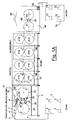
- FIGS 1A-B illustrate the general scheme of the system for continuously treating yarn with process fluids.
- Figure 2 and the detail of figure 2A illustrate the relevant details of the first device for imbibing the threads subjected to mercerisation.
- Figure 3 illustrates the essential details of the container in which the mercerisation reaction takes place.
- Figure 4 illustrates the details of the hydro-extraction and drawing device after the mercerising reaction.
- Figure 5 then illustrates the details of the container 40 in which the drawing of the yarn and its first washing with water take place.
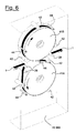
- Figure 6 illustrates the containers 40bis in which both the second washing and the neutralisation stages take place.
- figure 7 illustrates the details of the container 60 in which the drying and dehydration stage of the mercerised threads takes place.
- the yarn 1 to be treated is fed from a series of reels 2 arranged in parallel on a creel 3.
- the reels 2 yield a plurality of threads 1, which are kept separate and parallel during the entire process and along the entire sequence of mercerising apparatuses.
- the processing must be carried out on a congruous number of parallel threads 1, at least of the order of a few tens of threads at once, unwound with a speed at least of the order of 5-10 m/sec.
- the return of the parallel threads 1 is carried out with the pair of main guide rollers 4 with horizontal axis, which rotate at controlled speed and that determine the linear flow rate of the threads being processed taken to the mercerising unit, operating as outlined above at a linear speed of at least 5-10 m/sec.
- a relevant characteristic of the present invention lies in the operation of the treatment and in the structure of the mercerising reactor in which the treatment of the threads is carried out with sodium hydroxide alkaline solution.
- Such an operation is carried out in a closed parallelepiped-shaped container 5.
- the closed container 5 in general shaped like a wardrobe that can be opened for the intervention of operators, it is possible to maintain a controlled atmosphere, just like for the other further containers foreseen in the unit.
- the group of parallel threads 1 is deviated and guided firstly with rollers 7 with horizontal axis and worked with radial grooves that allow the threads to be kept separate and spaced apart during the entire mercerising reaction.
- the strip of parallel and separated threads 1 is fed to a first imbibing device 8 illustrated in greater detail in figure 2 , which shows plan, front and side section views. It consists of an imbibing plate 10 equipped with longitudinal grooves 11 that are independent and have constant pitch, which guide the threads 1 separately.
- the mercerising fluid consists of the alkaline solution, for example sodium hydroxide at 30° Be, and is sprayed on the plate 10 with sprayers 12 with nozzles at the grooves 11 in which the threads 1 run at a speed controlled by the initial guide rollers 4.
- the top part of the grooved plate 10 is protected with a cover 13.
- a sealing device 15 is arranged at the entry of the strip of threads 1 into the imbibing device 8 . It consists of an elongated tank 16, fed with the same mercerising solution and kept at atmospheric pressure, with a lower slit that comes out onto the grooves that guide and contain the threads in movement from left to right in the drawing according to the arrows F.
- the liquid head of the tank 16 allows a first imbibition at atmospheric pressure of the threads 1 and avoids the entry of air into the second treatment area with the pressurised solution.
- the plate 10 is worked with V-shaped grooves, whereas the cover 13 is provided with one or more sprayers 12 consisting of a series of pressurised injection micro-nozzles 18, shown in the detail of figure 2A and each arranged at each individual groove 11 crossed by a single thread.
- Each sprayer 12 and the tank 16 are fed with fittings 17 from a general feeding duct, not shown in the figures, which takes the alkaline mercerising solution at constant pressure and at controlled temperature.
- the temperature of the mercerising solution is kept at 30-35°C, whereas the injection overpressure is between 1 and 15 bars, preferably between 1.5 and 4 bars. Indeed, it has been found that the injection overpressure of the mercerising fluid causes a substantial increase in the mercerisation reaction kinetics, which can be attributed to a better exchange coefficient and a more efficient contact between the liquid phase and cellulose micelles, substantially accelerating the mercerising reaction. In conventional mercerisation techniques by immersion in baths or recipients at atmospheric pressure contact times of the order of minutes are required, whereas the technical solution according to the present invention allows such contact times to be drastically reduced, reducing them to the order of magnitude of 10 seconds.
- the structure and the operation of the rotary drums 20 and of the other elements inside the container 5 is illustrated in greater detail in figure 3 , in which they are shown in perspective view and transparently.
- the drums 20 are mounted parallel with substantially horizontal axis and they are equipped with a substantially smooth cylindrical surface.
- the incomplete 8-shaped spirals 21 are deposited on the surface of the drums 20.
- the deposit of the strip of threads 1 is guided with rotary combs 22, made up of a series of grooved ceramic bushings mounted with constant pitch on a shaft, and with the deviating rollers 24.
- the deviating rollers 24 have a substantially smooth surface, they are mounted with oblique rotation axis with respect to the axes of the drums 20 and they are equipped with means for varying their inclination.
- the inclination to the right or left of the axes of the deviating rollers 24 allows the progressive axial gauge between the 8-shaped spirals that wind on the drums 20 to be determined.
- the whole of the threads 1 in a strip enters into the rear part at the main guide rollers 4, passes the imbibing device 8, winds - starting from the right-hand drum 20 - with 8-shaped spirals that advance towards the front part of the container 5, and discharges - from the left-hand drum 20 - through the hydro-extraction and drawing device 27.
- imbibing device 8 to the hydro-extraction device 27 the mercerising reaction between the cellulose micelles of the yarn and the solution that imbibes the yarn itself takes place.
- the variation in inclination of the axes of the deviating rollers 24 allows the progressive axial gauge to be generated between the 8-shaped spirals that wind on the drums 20 and allows the number of spirals that can be carried by the available length of the drums 20 to be varied, thus determining the length of the path of the strip of threads 1 and its treatment time with alkaline solution.
- substantially "square" cylindrical drums 20 with a diameter and length of about 1000 mm, it is possible to wind 50-100 m of strip of threads 1 and to carry out reaction times within the range of 8-15 seconds, which corresponds to the time of complete "re-entry", in other words the time for completion of the reactions between the cellulose and the alkaline solution, which result in the shortening of the yarn by values of 10-20% according to the type of yarn and the original cotton.
- one or more series of further spray nozzles is arranged close to the surface of the drums themselves, to renew the contact between yarn and alkaline solution.
- Such spray nozzles are placed on nozzle-carrying rods 25 and are analogous to those that equip the imbibing device 8, but operating at lower pressure, and the position of a pair of rods 25 thereof is shown as an example in figure 1A .
- the strip of threads 1 is discharged with the hydro-extraction and drawing device 27 after the mercerising reaction. It is shown in figure 4 with its essential components.
- the strip of mercerised threads 1 still imbibed with alkaline solution passes from idle deviating rollers 28 and reaches the hydro-extraction device 29 consisting of a motorised roller 30 against which two idle counter-rollers 31 are pressed, preferably made from polymeric elastic material.
- Such a roller 30 rotates at the linear speed of the strip of threads 1 fed, decreased by the expected percentage shrinkage for the mercerisation.
- All of the motorisations of the shafts of the rotary members inside the container 5, in other words the drums 20, the rotary combs 22, the deviating rollers 24 and the roller 30, are controlled with independent actuations, for example through inverters, and the various angular speeds are synchronised with each other to obtain and keep the linear speeds for the drums 20 and the deviating rollers 24 coherent with that of the strip of threads 1 being processed.
- the rotation speed of the combs 22, on the other hand, is lower (2-10 revolutions per minute); it is carried out to limit the erosion phenomena of the ceramic bushes of which they consist.
- a device 35 for capturing the ends of the threads that have broken is arranged at the motorised roller 30 of the hydro-extraction device 29. Indeed, there is greater probability of breaking at the drawing of the mercerised threads and, in this case, the ends tend to stick and wind onto the roller 30.
- the device 35 for example, can consist of a suction mouth 36 connected to a suction duct 37; the top edge of its suction slit 38 is made from polymeric material and is arranged to scrape the metallic surface of the roller 30. In this way, the possible end that winds onto the surface of said roller is stopped and sucked up by the mouth 36.
- the device 35 for capturing the ends can be made with a rotary brush of bristles made from polymeric material that, mounted in the same position as the mouth 36 and made to rotate at a high speed, clears the roller 30 of the possible ends that would otherwise wind onto its surface.
- said strip After passing into the container 5 in which the contact is made between the threads 1 in a strip and the alkaline mercerising solution, said strip is fed for washing with water.
- the washing can be carried out in many stages with water in countercurrent and at decreasing temperature, according to methods already known in the field.
- the first washing stage is carried out in the container 40, illustrated in figure 5 with its essential components. In it the washing operation of the yarn treated with the alkaline solution and coming from the container 5 takes place.
- the strip of threads 1 is guided and deviated by a series of idle rollers 28 up to the rotary cylindrical drums 41A, B made from metallic material and with a smooth surface.
- the strip of threads is inserted and held between the surface of the drums 41A, B and a series of idle cylindrical counter-rollers 42 that wrap around them and are kept pressed to grip said strip. At each passage under such counter-rollers the liquid contained by the strip of threads is thus squeezed out. Downstream of the counter-rollers 42 a series of spray nozzles 44 of the washing water is inserted.
- the washing consists of an alternating sequence of imbibition and squeezing of the threads 1 in a strip to remove the residues of the alkaline mercerising solution, thus discharging the strip of threads washed through the deviating idle roller 28 arranged downstream of the drum 41B.
- the yarn is drawn as a consequence of the different linear actuation speed of the roller 30 and of the drum 41A, recovering the lost length through "shrinkage" and giving the definitive tension required to fully obtain the mercerising effects.
- the second washing stage is carried out in the container 40bis shown in figure 6 in its essential components, having the same structure and operations as the previous one, apart from the drawing function and the direction of the thread arriving from the previous stage. Therefore, the same reference numerals have been kept for the components present in the container 40bis.
- the motorisation of the shafts of the drums 41A, B is also controlled with independent actuation, for example through an inverter, given that the various angular speeds of the mercerising device are synchronised to obtain and keep coherent speeds within the device.
- the strip of threads 1 washed in the previous washing units is then subjected to neutralisation, for example with a diluted acetic or citric acid solution with pH of 2-2.5, inside the relative containers.
- neutralisation for example with a diluted acetic or citric acid solution with pH of 2-2.5, inside the relative containers.
- the neutralisation is shown in two stages: in the first neutralisation with acid is carried out, whereas in the second the final washing with water for greater purity is carried out.
- the neutralisation unit is totally analogous to the washing units and operates according to the same general scheme, apart from that the washing operates with water whereas neutralisation operates with acid solutions.
- 40 and 40bis plates 26, 46 for collecting the part of the various treatment fluids that is not held by the threads being treated are arranged, for its recovery and reuse, after a suitable reconditioning. As far as the washing waters are concerned, the criterion of countercurrent is used.
- the washing and neutralisation operations of the strip of threads 1 are thus carried out inside the containers 40 and 40bis with S-shaped paths around the drums 41A, B, on which an alternating sequence of imbibition and squeezing is carried out with the washing waters and with the acid solution, respectively.
- the strip of washed and neutralised threads 1 is then subjected to a drying and exsiccation stage, in the drying unit inside the container 60 shown in figure 7 in its essential components.
- the drying and exsiccation unit has an analogous structure to that of the treatment unit with alkaline solution.
- the strip of threads 1 is made to pass onto the surface of two rotary drums 61, heated with steam or with diathermal oil to suitable temperature.
- the strip of threads 1 is wound many times onto the hot surface of the drums 61 always with incomplete 8-shaped spirals.
- the deposit of the strip of threads 1 is regulated with the deviating rollers 62, totally analogous to the deviating rollers 24 of the container 5, also with a rotation axis oblique to the axes of the drums 61.
- the variation in inclination of the axes of the deviating rollers 62 allows the progressive axial gauge between the 8-shaped spirals that wind onto the drums 61 to be generated and allows their number to be varied, thus determining the length of the path of the strip of threads 1 and its time spent inside the exsiccation unit.
- the strip of threads 1 is discharged from the drying and exsiccation unit of the container 60 with one or more pairs of discharging rollers 64.
- a suction hood 65 for the vapours developed during the course of the drying and exsiccation of the threads takes these vapours away.
- the strip of threads 1 coming out from the exsiccation unit is then sent for the individual winding of each thread and does not require any particular operation to separate the threads 1 that make up the strip, since such threads have always kept their individuality.
- the winder 70 a series of reels 72 is produced that each contain one of the threads 1 that have been mercerised in the plant upstream.
- An important characteristic of the present invention is the way in which the threads make contact with the process fluids, alkaline solution, washing waters and neutralisation reagents, in the case of the mercerisation of cotton.
- the contact and the relative reactions are carried out by taking and feeding the process fluids directly to the single thread and avoiding the immersions in tanks or reactors of the prior art, which give a disadvantageous quantity ratio between the worked threads and the process fluids, In particular, the stage of reaction with the alkaline solutions takes place in a quite short time period.
- injector nozzles 12 in the imbibing device 8 which engage the threads 1 under treatment individually, injecting the alkaline solution under pressure, allows the mercerisation treatment to be completed in a time of around a tenth of a second and it does not require further reaction stages to achieve the desired result.
- the mercerisation process described up to now allows significant advantages compared to the processes of the prior art.
- the threads are worked as such and individually, without requiring them to firstly be joined in a package in an integral bundle, skeins or beams and later requiring their separation.
- the present invention allows work with good productivity since the strip of threads runs in the plant at a high speed going from the reels 2 and ending at the reels 72 for collecting the mercerised product.
- a further advantage lies in the small amount of fluids used and their greater yield, reducing the environmental implications.
- Processing with individual threads means that each of the threads 1 being treated goes from a reel 2 of index N in the creel 3 and reaches a reel 72 of index N.
- the winding head of index N indicates the absence of thread: it is quite simple and easy to indicate such an event to the creel 3 and consequently to thus automatically cause the relative end being fed to be cut and stop its winding head.
Landscapes
- Engineering & Computer Science (AREA)
- Textile Engineering (AREA)
- Treatment Of Fiber Materials (AREA)
- Chemical Or Physical Treatment Of Fibers (AREA)
Claims (10)
- Procédé pour le mercerisage en continu de fils de cellulose (1), comprenant le traitement des fils avec une solution alcaline, pour l'étirage des fils, le lavage à l'eau et la neutralisation du résidu d'alcalinité encore présente dans les fils, en partant des bobines initiales (2) de fils et pour produire des bobines finies (72) de fils mercerisés, le procédé étant exécuté en continu sur une pluralité de fils (1) le long de tout le dispositif de mercerisage et dans lequel les fluides de traitement sont délivrés directement sur les fils (1) sans immersion dans des bains de traitement, lesdits fils étant déplacés des bobines initiales (2) aux bobines finies (72), les fils (1) étant premièrement soumis à une imbibition avec la solution alcaline dans un dispositif d'imbibition (8) et passent ensuite sur la surface de tambours rotatifs (20), étant enroulés plusieurs fois avec des spirales en forme de 8 incomplet (21), déterminant ainsi avec le nombre de spirales la longueur du parcours de fils (1) et leur temps de traitement avec la solution alcaline, alors que la réaction de mercerisage entre la solution d'imbibition et les mélanges de cellulose a lieu à l'intérieur de ceux-ci, caractérisé en ce que les fils (1) sont sous forme de bande, maintenus séparés et espacés durant toute la réaction de mercerisage, et caractérisé en outre en ce que l'imbibition des fils (1) est effectuée en évitant l'entrée d'air, avec une série de micro-buses d'injection sous pression (18), chacune agencée au niveau d'une rainure longitudinale (11) traversée par un unique fil (1), les rainures longitudinales (11) guidant ainsi les fils (1) à l'intérieur, séparément et à grande vitesse.
- Procédé pour le mercerisage de fils selon la revendication 1, caractérisé en ce que la surpression d'injection dans les micro-buses (18) est entre 1 et 15 bar, et de préférence entre 1,5 et 4 bar.
- Procédé pour le mercerisage de fils selon la revendication 1, caractérisé en ce qu'entre les tambours (20), dans les parties libres des spirales (21) de la bande de fils (1), le contact entre fil et solution alcaline est renouvelé avec d'autres buses de vaporisation disposées sur des tiges de support de buses (25).
- Procédé pour le mercerisage de fils selon la revendication 1, caractérisé en ce que, à la fin du traitement avec la solution alcaline, la bande de fils (1) est retirée avec un rouleau (30) tournant à la vitesse linéaire de la bande de fils (1) délivrée, diminuée du pourcentage de retrait prévu pour le mercerisage, en permettant ainsi aux fils de se retirer dans la partie de bande libre de fils (1) entre la dernière spirale et le rouleau (30).
- Procédé pour le mercerisage de fils selon la revendication 1, caractérisé en ce que les traitements de lavage et neutralisation sont exécutés en enroulant la bande de fils (1) avec des parcours en forme de S autour de tambours rotatifs (41A,B) sur lesquels une séquence alternée d'imbibition et d'hydro-extraction a lieu avec de l'eau de lavage et avec une solution acide, respectivement.
- Procédé pour le mercerisage de fils selon les revendications 4 et 5, caractérisé en ce que, en passant du rouleau (30) au tambour (41A) et du premier contre-rouleau (42) de la première unité de lavage, l'étirement du fil a lieu en conséquence de la vitesse d'actionnement linéaire différente du rouleau (30) et du tambour (41A).
- Dispositif pour le mercerisage en continu de fils de cellulose, comprenant des dispositifs pour le traitement des fils avec une solution alcaline, pour l'étirage des fils, pour le lavage à l'eau et la neutralisation du résidu d'alcalinité encore présente dans les fils, en partant des bobines initiales (2) de fils et pour produire des bobines finies (72) de fils mercerisés, ces dispositifs opérant en continu sur une pluralité de fils (1) le long de tout le dispositif de mercerisage, délivrant les fluides de traitement directement sur les fils (1) sans immersion dans des bains de traitement, et comprenant un dispositif d'imbibition (8) avec la solution alcaline et deux tambours rotatifs (20), sur lesquels la bande de fils est enroulée plusieurs fois avec des spirales en forme de 8 incomplet (21), déterminant ainsi la longueur du parcours le long duquel a lieu la réaction de mercerisage entre la solution d'imbibition et les micelles de cellulose, caractérisé en ce que le dispositif comprend des moyens (7) qui permettent aux fils (1) d'être maintenus séparés et espacés durant toute la réaction de mercerisage, et caractérisé en outre en ce que le dispositif d'imbibition (8) comprend une plaque d'imbibition (10) pourvue de rainures longitudinales indépendantes (11), lesquelles guident séparément à l'intérieur un unique fil (1), et sur lesquelles la solution alcaline est vaporisée avec des vaporisateurs (12) avec des micro-buses (18), chacune agencée au niveau des rainures longitudinales (11) dans lesquelles passe le fil (1), la partie supérieure de la plaque à rainures (10) étant protégée par une plaque de couverture (13).
- Dispositif pour le traitement en continu de fils avec des fluides de traitement selon la revendication 7, caractérisé en ce que les deux tambours rotatifs (20) sont munis de moyens pour déterminer le gabarit des spirales en forme de 8 incomplet et pour faire varier le nombre de spirales qui peuvent être portées par la longueur disponible des tambours (20), en déterminant ainsi la longueur du parcours de la bande de fils (1) et son temps de traitement avec la solution alcaline.
- Dispositif pour le traitement en continu de fils avec des fluides de traitement selon la revendication 7, caractérisé en ce que, à l'entrée de la bande de fils (1) dans le dispositif d'imbibition (8), un dispositif d'étanchéité (15) est agencé, comprenant un réservoir (16) alimenté avec la même solution de mercerisage, avec une fente inférieure qui vient sur les rainures (11) qui fournit une charge de liquide au début desdites rainures et une première imprégnation des fils (1).
- Dispositif pour le traitement en continu de fils avec des fluides de traitement selon la revendication 8, caractérisé en ce que les moyens pour déterminer le gabarit des spirales enroulées sur les tambours rotatifs (20) comprennent des rouleaux de renvoi (24) montés avec un axe de rotation oblique par rapport aux axes des tambours (20) et équipés de moyens pour faire varier leur inclinaison, pour générer le gabarit axial progressif entre les spirales en forme de 8 incomplet qui s'enroulent sur les tambours (20).
Applications Claiming Priority (1)
| Application Number | Priority Date | Filing Date | Title |
|---|---|---|---|
| ITMI20061767 ITMI20061767A1 (it) | 2006-09-15 | 2006-09-15 | Procedimento e dispositivo per la mercerizzazione in continuo di filati tessili |
Publications (3)
| Publication Number | Publication Date |
|---|---|
| EP1900864A2 EP1900864A2 (fr) | 2008-03-19 |
| EP1900864A3 EP1900864A3 (fr) | 2009-08-05 |
| EP1900864B1 true EP1900864B1 (fr) | 2011-03-30 |
Family
ID=38829569
Family Applications (1)
| Application Number | Title | Priority Date | Filing Date |
|---|---|---|---|
| EP20070115878 Active EP1900864B1 (fr) | 2006-09-15 | 2007-09-07 | Procédé et dispositif pour le mercerisage en continu des fils textiles |
Country Status (4)
| Country | Link |
|---|---|
| EP (1) | EP1900864B1 (fr) |
| CN (1) | CN101144235B (fr) |
| DE (1) | DE602007013500D1 (fr) |
| IT (1) | ITMI20061767A1 (fr) |
Families Citing this family (5)
| Publication number | Priority date | Publication date | Assignee | Title |
|---|---|---|---|---|
| CN101525826B (zh) * | 2009-03-10 | 2012-05-09 | 东华大学 | 一种纱线束状连续回流丝光的方法 |
| ITMI20121361A1 (it) * | 2012-08-01 | 2014-02-02 | Reggiani Macchine Spa | Macchina per la mercerizzazione di filati |
| ITMI20121360A1 (it) * | 2012-08-01 | 2014-02-02 | Reggiani Macchine Spa | Macchina e metodo per la mercerizzazione di filati o tessuti |
| CN110011226B (zh) * | 2019-03-29 | 2024-12-03 | 北京理工大学 | 布线装置 |
| CN113403764B (zh) * | 2021-07-02 | 2024-01-09 | 台嘉蚌埠玻璃纤维有限公司 | 一种可自动冲洗的拉丝机及冲洗方法 |
Family Cites Families (10)
| Publication number | Priority date | Publication date | Assignee | Title |
|---|---|---|---|---|
| US2292629A (en) * | 1939-08-12 | 1942-08-11 | American Rayon Company Inc | Method for imparting finish to cotton yarn |
| GB960150A (en) * | 1963-04-11 | 1964-06-10 | Inst Textilmaschinen | Improvements in or relating to apparatus for sizing warp threads |
| GB1268376A (en) * | 1968-06-06 | 1972-03-29 | Stone Platt Crawley Ltd Former | Improvements relating to conveyors |
| US3766581A (en) * | 1970-08-05 | 1973-10-23 | Kanegafuchi Spinning Co Ltd | Process for continuously treating thread |
| US3864949A (en) * | 1970-08-05 | 1975-02-11 | Kanegafuchi Spinning Co Ltd | Apparatus for continuously treating thread |
| DE4121593A1 (de) * | 1991-06-29 | 1993-01-07 | Croon Lucke Maschinen | Vorrichtung zum kontinuierlichen behandeln von garnen in fluiden medien |
| FR2739880B1 (fr) * | 1995-10-13 | 1997-12-05 | Superba Sa | Procede de teinture en continu de fils, en particulier a base de fibres cellulosiques avec des colorants reactifs, et dispositif pour la mise en oeuvre de ce procede |
| ITMI20021220A1 (it) | 2002-06-05 | 2003-12-05 | Savio Macchine Tessili Spa | Procedimento e dispositivo per il mercerizzo in continuo dei filati tessili |
| ITMI20021221A1 (it) | 2002-06-05 | 2003-12-05 | Savio Macchine Tessili Spa | Dispositivo per il trattamento in continuo dei filati con fluidi di processo |
| ITMI20021223A1 (it) | 2002-06-05 | 2003-12-05 | Savio Macchine Tessili Spa | Sistema di trattamento in continuo dei filati con fluidi di processo particolarmente per la loro mercerizzazione sotto tensione |
-
2006
- 2006-09-15 IT ITMI20061767 patent/ITMI20061767A1/it unknown
-
2007
- 2007-09-07 EP EP20070115878 patent/EP1900864B1/fr active Active
- 2007-09-07 DE DE200760013500 patent/DE602007013500D1/de active Active
- 2007-09-14 CN CN2007101536904A patent/CN101144235B/zh active Active
Also Published As
| Publication number | Publication date |
|---|---|
| EP1900864A2 (fr) | 2008-03-19 |
| ITMI20061767A1 (it) | 2008-03-16 |
| CN101144235A (zh) | 2008-03-19 |
| EP1900864A3 (fr) | 2009-08-05 |
| CN101144235B (zh) | 2012-11-14 |
| DE602007013500D1 (de) | 2011-05-12 |
Similar Documents
| Publication | Publication Date | Title |
|---|---|---|
| EP1900864B1 (fr) | Procédé et dispositif pour le mercerisage en continu des fils textiles | |
| EP3152358B1 (fr) | Procédé de teinture et de finition de matériau textile et appareil correspondant | |
| US2041338A (en) | Continuous rayon spinning and processing machine | |
| US2367730A (en) | Textile dyeing and finishing, method and product | |
| US4416124A (en) | Sheet-dyeing apparatus | |
| EP1369521B1 (fr) | Procédé pour le mercerisage en continu des fils textiles | |
| KR20130057044A (ko) | 플로킹 카펫의 프린팅 공정 설비 | |
| US7090702B2 (en) | Continuous treatment system of yarns with process fluids, particularly for their mercerization under tension | |
| US3766581A (en) | Process for continuously treating thread | |
| EP0489191A1 (fr) | Procédé et appareillage de mercerisage en continu | |
| US4376632A (en) | Process and plant for the continuous mercerization of raw or colored open or tubular knitted fabric | |
| DE4218551A1 (de) | Verfahren zur kontinuierlichen Behandlung eines endlosen Garnbündels | |
| US7140207B2 (en) | Device for the continuous treatment of yarns with process fluids | |
| US4263008A (en) | Method and apparatus for continuously carrying out weight reduction and mercerization of cloth material | |
| US2139017A (en) | Process for producing filaments like horsehair | |
| KR102185270B1 (ko) | 인견직물의 크리즈 가공장치 및 가공방법 | |
| JPS5953940B2 (ja) | 繊維品の連続洗浄方法 | |
| DE2527450A1 (de) | Vorrichtung zum behandeln, insbesondere faerben von garnen | |
| US3864949A (en) | Apparatus for continuously treating thread | |
| IT8983488A1 (it) | Procedimento di mercerizzazione in continuo e apparecchiatura adottante tale procedimento | |
| DE723363C (de) | Verfahren und Einrichtung zur Gewinnung kotonisierter Fasern aus Bastfasern in Bandform | |
| EP0977916A1 (fr) | Procede de teinture unie en continu de fils en defilement et installation pour la mise en oeuvre de ce procede | |
| GB391863A (en) | Improvements in or relating to the treatment and manufacture of artificial yarns, threads, filaments and the like | |
| DE2116C (de) | Verfahren zum Glätten und Fertigmachen von Garnen | |
| GB2077783A (en) | Mercerising cloth |
Legal Events
| Date | Code | Title | Description |
|---|---|---|---|
| PUAI | Public reference made under article 153(3) epc to a published international application that has entered the european phase |
Free format text: ORIGINAL CODE: 0009012 |
|
| AK | Designated contracting states |
Kind code of ref document: A2 Designated state(s): AT BE BG CH CY CZ DE DK EE ES FI FR GB GR HU IE IS IT LI LT LU LV MC MT NL PL PT RO SE SI SK TR |
|
| AX | Request for extension of the european patent |
Extension state: AL BA HR MK YU |
|
| RIN1 | Information on inventor provided before grant (corrected) |
Inventor name: CEOLIN, MAURO Inventor name: MINUTI, MARIO Inventor name: QUAIA, AMEDEO Inventor name: BADIALI, ROBERTO |
|
| PUAL | Search report despatched |
Free format text: ORIGINAL CODE: 0009013 |
|
| AK | Designated contracting states |
Kind code of ref document: A3 Designated state(s): AT BE BG CH CY CZ DE DK EE ES FI FR GB GR HU IE IS IT LI LT LU LV MC MT NL PL PT RO SE SI SK TR |
|
| AX | Request for extension of the european patent |
Extension state: AL BA HR MK RS |
|
| 17P | Request for examination filed |
Effective date: 20100114 |
|
| 17Q | First examination report despatched |
Effective date: 20100208 |
|
| AKX | Designation fees paid |
Designated state(s): CH DE IT LI TR |
|
| GRAP | Despatch of communication of intention to grant a patent |
Free format text: ORIGINAL CODE: EPIDOSNIGR1 |
|
| GRAS | Grant fee paid |
Free format text: ORIGINAL CODE: EPIDOSNIGR3 |
|
| GRAA | (expected) grant |
Free format text: ORIGINAL CODE: 0009210 |
|
| AK | Designated contracting states |
Kind code of ref document: B1 Designated state(s): CH DE IT LI TR |
|
| REG | Reference to a national code |
Ref country code: CH Ref legal event code: EP |
|
| REF | Corresponds to: |
Ref document number: 602007013500 Country of ref document: DE Date of ref document: 20110512 Kind code of ref document: P |
|
| REG | Reference to a national code |
Ref country code: DE Ref legal event code: R096 Ref document number: 602007013500 Country of ref document: DE Effective date: 20110512 |
|
| REG | Reference to a national code |
Ref country code: CH Ref legal event code: NV Representative=s name: PATENTANWAELTE SCHAAD, BALASS, MENZL & PARTNER AG |
|
| PLBE | No opposition filed within time limit |
Free format text: ORIGINAL CODE: 0009261 |
|
| STAA | Information on the status of an ep patent application or granted ep patent |
Free format text: STATUS: NO OPPOSITION FILED WITHIN TIME LIMIT |
|
| 26N | No opposition filed |
Effective date: 20120102 |
|
| REG | Reference to a national code |
Ref country code: DE Ref legal event code: R097 Ref document number: 602007013500 Country of ref document: DE Effective date: 20120102 |
|
| REG | Reference to a national code |
Ref country code: DE Ref legal event code: R082 Ref document number: 602007013500 Country of ref document: DE Representative=s name: SCHWABE SANDMAIR MARX, DE |
|
| REG | Reference to a national code |
Ref country code: CH Ref legal event code: PFA Owner name: SAVIO MACCHINE TESSILI S.P.A., IT Free format text: FORMER OWNER: PENELOPE S.P.A., IT Ref country code: CH Ref legal event code: PFUS Owner name: PENELOPE S.P.A., IT Free format text: FORMER OWNER: SAVIO MACCHINE TESSILI S.P.A., IT Ref country code: CH Ref legal event code: PUE Owner name: MARIO MINUTI, IT Free format text: FORMER OWNER: SAVIO MACCHINE TESSILI S.P.A., IT |
|
| REG | Reference to a national code |
Ref country code: DE Ref legal event code: R082 Ref document number: 602007013500 Country of ref document: DE Representative=s name: SCHWABE SANDMAIR MARX, DE Effective date: 20130624 Ref country code: DE Ref legal event code: R081 Ref document number: 602007013500 Country of ref document: DE Owner name: MINUTI, MARIO, IT Free format text: FORMER OWNER: SAVIO MACCHINE TESSILI S.P.A., PORDENONE, IT Effective date: 20130624 Ref country code: DE Ref legal event code: R082 Ref document number: 602007013500 Country of ref document: DE Representative=s name: SCHWABE SANDMAIR MARX PATENTANWAELTE RECHTSANW, DE Effective date: 20130624 |
|
| P01 | Opt-out of the competence of the unified patent court (upc) registered |
Effective date: 20230523 |
|
| PGFP | Annual fee paid to national office [announced via postgrant information from national office to epo] |
Ref country code: DE Payment date: 20240927 Year of fee payment: 18 |
|
| PGFP | Annual fee paid to national office [announced via postgrant information from national office to epo] |
Ref country code: CH Payment date: 20241002 Year of fee payment: 18 |
|
| PGFP | Annual fee paid to national office [announced via postgrant information from national office to epo] |
Ref country code: TR Payment date: 20250822 Year of fee payment: 19 Ref country code: IT Payment date: 20250908 Year of fee payment: 19 |