EP1900886B1 - Isolant multicouche pour l'isolation thermique et phonique - Google Patents
Isolant multicouche pour l'isolation thermique et phonique Download PDFInfo
- Publication number
- EP1900886B1 EP1900886B1 EP07291030A EP07291030A EP1900886B1 EP 1900886 B1 EP1900886 B1 EP 1900886B1 EP 07291030 A EP07291030 A EP 07291030A EP 07291030 A EP07291030 A EP 07291030A EP 1900886 B1 EP1900886 B1 EP 1900886B1
- Authority
- EP
- European Patent Office
- Prior art keywords
- insulation
- strip
- insulator
- scale
- measuring scale
- Prior art date
- Legal status (The legal status is an assumption and is not a legal conclusion. Google has not performed a legal analysis and makes no representation as to the accuracy of the status listed.)
- Not-in-force
Links
- 238000005520 cutting process Methods 0.000 claims abstract description 10
- 229910052782 aluminium Inorganic materials 0.000 claims abstract description 3
- XAGFODPZIPBFFR-UHFFFAOYSA-N aluminium Chemical compound [Al] XAGFODPZIPBFFR-UHFFFAOYSA-N 0.000 claims abstract description 3
- 238000009413 insulation Methods 0.000 claims description 44
- 239000010410 layer Substances 0.000 claims description 7
- 239000002184 metal Substances 0.000 claims description 5
- 229910052751 metal Inorganic materials 0.000 claims description 5
- 238000004026 adhesive bonding Methods 0.000 claims description 3
- 229920002994 synthetic fiber Polymers 0.000 claims description 2
- 239000002365 multiple layer Substances 0.000 claims 5
- 239000004411 aluminium Substances 0.000 claims 1
- 238000010276 construction Methods 0.000 claims 1
- 239000006260 foam Substances 0.000 claims 1
- 239000012212 insulator Substances 0.000 abstract description 37
- 238000005259 measurement Methods 0.000 abstract description 19
- 238000000576 coating method Methods 0.000 abstract description 11
- 239000011248 coating agent Substances 0.000 abstract description 7
- 239000000463 material Substances 0.000 abstract description 6
- 238000009434 installation Methods 0.000 abstract description 3
- 239000000853 adhesive Substances 0.000 description 3
- 230000001070 adhesive effect Effects 0.000 description 3
- 239000004020 conductor Substances 0.000 description 2
- 239000000470 constituent Substances 0.000 description 2
- 238000004519 manufacturing process Methods 0.000 description 2
- 239000011490 mineral wool Substances 0.000 description 2
- 238000009958 sewing Methods 0.000 description 2
- 238000003466 welding Methods 0.000 description 2
- RNFJDJUURJAICM-UHFFFAOYSA-N 2,2,4,4,6,6-hexaphenoxy-1,3,5-triaza-2$l^{5},4$l^{5},6$l^{5}-triphosphacyclohexa-1,3,5-triene Chemical compound N=1P(OC=2C=CC=CC=2)(OC=2C=CC=CC=2)=NP(OC=2C=CC=CC=2)(OC=2C=CC=CC=2)=NP=1(OC=1C=CC=CC=1)OC1=CC=CC=C1 RNFJDJUURJAICM-UHFFFAOYSA-N 0.000 description 1
- 239000002390 adhesive tape Substances 0.000 description 1
- 230000004888 barrier function Effects 0.000 description 1
- 230000015572 biosynthetic process Effects 0.000 description 1
- 239000011152 fibreglass Substances 0.000 description 1
- 239000003063 flame retardant Substances 0.000 description 1
- 230000010354 integration Effects 0.000 description 1
- 238000000034 method Methods 0.000 description 1
- 239000002985 plastic film Substances 0.000 description 1
- 229920006255 plastic film Polymers 0.000 description 1
- 239000002984 plastic foam Substances 0.000 description 1
- 229920001296 polysiloxane Polymers 0.000 description 1
- 238000011084 recovery Methods 0.000 description 1
- 239000002356 single layer Substances 0.000 description 1
- 238000004804 winding Methods 0.000 description 1
Images
Classifications
-
- E—FIXED CONSTRUCTIONS
- E04—BUILDING
- E04B—GENERAL BUILDING CONSTRUCTIONS; WALLS, e.g. PARTITIONS; ROOFS; FLOORS; CEILINGS; INSULATION OR OTHER PROTECTION OF BUILDINGS
- E04B1/00—Constructions in general; Structures which are not restricted either to walls, e.g. partitions, or floors or ceilings or roofs
- E04B1/62—Insulation or other protection; Elements or use of specified material therefor
- E04B1/74—Heat, sound or noise insulation, absorption, or reflection; Other building methods affording favourable thermal or acoustical conditions, e.g. accumulating of heat within walls
- E04B1/88—Insulating elements for both heat and sound
-
- B—PERFORMING OPERATIONS; TRANSPORTING
- B32—LAYERED PRODUCTS
- B32B—LAYERED PRODUCTS, i.e. PRODUCTS BUILT-UP OF STRATA OF FLAT OR NON-FLAT, e.g. CELLULAR OR HONEYCOMB, FORM
- B32B15/00—Layered products comprising a layer of metal
- B32B15/04—Layered products comprising a layer of metal comprising metal as the main or only constituent of a layer, which is next to another layer of the same or of a different material
- B32B15/08—Layered products comprising a layer of metal comprising metal as the main or only constituent of a layer, which is next to another layer of the same or of a different material of synthetic resin
-
- E—FIXED CONSTRUCTIONS
- E04—BUILDING
- E04B—GENERAL BUILDING CONSTRUCTIONS; WALLS, e.g. PARTITIONS; ROOFS; FLOORS; CEILINGS; INSULATION OR OTHER PROTECTION OF BUILDINGS
- E04B1/00—Constructions in general; Structures which are not restricted either to walls, e.g. partitions, or floors or ceilings or roofs
- E04B1/62—Insulation or other protection; Elements or use of specified material therefor
- E04B1/74—Heat, sound or noise insulation, absorption, or reflection; Other building methods affording favourable thermal or acoustical conditions, e.g. accumulating of heat within walls
- E04B1/76—Heat, sound or noise insulation, absorption, or reflection; Other building methods affording favourable thermal or acoustical conditions, e.g. accumulating of heat within walls specifically with respect to heat only
- E04B1/78—Heat insulating elements
-
- F—MECHANICAL ENGINEERING; LIGHTING; HEATING; WEAPONS; BLASTING
- F16—ENGINEERING ELEMENTS AND UNITS; GENERAL MEASURES FOR PRODUCING AND MAINTAINING EFFECTIVE FUNCTIONING OF MACHINES OR INSTALLATIONS; THERMAL INSULATION IN GENERAL
- F16L—PIPES; JOINTS OR FITTINGS FOR PIPES; SUPPORTS FOR PIPES, CABLES OR PROTECTIVE TUBING; MEANS FOR THERMAL INSULATION IN GENERAL
- F16L59/00—Thermal insulation in general
- F16L59/02—Shape or form of insulating materials, with or without coverings integral with the insulating materials
- F16L59/026—Mattresses, mats, blankets or the like
-
- E—FIXED CONSTRUCTIONS
- E04—BUILDING
- E04B—GENERAL BUILDING CONSTRUCTIONS; WALLS, e.g. PARTITIONS; ROOFS; FLOORS; CEILINGS; INSULATION OR OTHER PROTECTION OF BUILDINGS
- E04B1/00—Constructions in general; Structures which are not restricted either to walls, e.g. partitions, or floors or ceilings or roofs
- E04B1/62—Insulation or other protection; Elements or use of specified material therefor
- E04B1/74—Heat, sound or noise insulation, absorption, or reflection; Other building methods affording favourable thermal or acoustical conditions, e.g. accumulating of heat within walls
- E04B2001/741—Insulation elements with markings, e.g. identification or cutting template
-
- E—FIXED CONSTRUCTIONS
- E04—BUILDING
- E04B—GENERAL BUILDING CONSTRUCTIONS; WALLS, e.g. PARTITIONS; ROOFS; FLOORS; CEILINGS; INSULATION OR OTHER PROTECTION OF BUILDINGS
- E04B1/00—Constructions in general; Structures which are not restricted either to walls, e.g. partitions, or floors or ceilings or roofs
- E04B1/62—Insulation or other protection; Elements or use of specified material therefor
- E04B1/74—Heat, sound or noise insulation, absorption, or reflection; Other building methods affording favourable thermal or acoustical conditions, e.g. accumulating of heat within walls
- E04B1/76—Heat, sound or noise insulation, absorption, or reflection; Other building methods affording favourable thermal or acoustical conditions, e.g. accumulating of heat within walls specifically with respect to heat only
- E04B2001/7691—Heat reflecting layers or coatings
Definitions
- the present invention relates to a multilayer insulation for building thermal and sound insulation, said insulation being in the form of a strip cut transversely into sections during laying.
- each insulator is in the form of superimposed sheets of variable material, the constituent sheets of the outer faces of said insulator being reflective, that is to say having an emissivity of less than 0.7.
- the manufacture of these insulators is often made from sheets arranged in rolls. These rollers are unwound simultaneously and the sheets are thus assembled by welding, sewing, gluing or any other assembly method to keep them superimposed.
- each insulator is in the finished state in the form of a width width that can vary between 0.5 and 2 meters and a length of up to several meters, the thickness generally being between 8 and 50 mm. .
- the document EP 0867 572 discloses an insulator in the form of a mineral wool product formed from a mineral wool mat and a sheet-like backing of synthetic material, metal, fiberglass mat or auxiliary paper. This product is characterized by the fact that the counter-collage presents a mark configured by signs in the form of numbers, letters or pictograms which contain a meaning. At no time is the notion measurement scale is specified.
- the document DE 1,026,1087 describes a monolayer insulation.
- An object of the present invention is therefore to provide a multilayer insulator whose design eliminates the need for the use of a measuring tool, such as a winding meter, and allows to exempt from any measurement prior to installation.
- the subject of the invention is a multilayer insulator according to claim 1.
- At least one measurement scale with the insulation allows the operator by direct reading to identify the band size he wishes to obtain before proceeding to the transverse cutting of the strip in order to obtain a stretch of tape.
- the multilayer insulator 1, object of the invention is in the form of a strip which, before laying on a surface to be insulated, is wound to form a roll.
- the longitudinal axis of the strip extends parallel to the direction of unwinding of the strip.
- This insulator 1 is generally intended to be assembled with at least one similar insulator by partially covering said insulators with each other. The partial recovery is generally performed at the longitudinal edges of said strips. These strips can thus be laid vertically and juxtaposed partially or be laid horizontally and partially overlapped.
- the insulation therefore comprises at least one overlapping zone 6, preferably two substantially parallel overlapping zones 6, each positioned in the vicinity of a free longitudinal edge of the insulation. It is also possible to imagine the installation of such insulation by putting edge to edge with a similar insulator. In this case, the insulation is free of overlap zone 6.
- the strip constituting the insulator, comprises a scale 2 measurement disposed parallel to the longitudinal axis of the strip.
- This measurement scale interconnects two opposite transverse edges of the strip so as to locate, by direct reading, the desired location of a cutting line according to the dimensional characteristics of the strip section to be obtained. Due to its layout, the measurement scale is discovered as the tape unfolds.
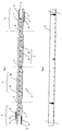
- a band may have several scales of measurement that are generally parallel to one another as shown in figure 1 .
- the scale 2 of measurement or each scale 2 of measurement is made in the form of a strip 9 peelable, reported and secured generally by bonding to the insulator 1.
- the insulation is formed of a core 3 covered on each of its faces with a thermally conductive and reflective coating 4, such as a metallic or metallized coating.
- the coatings 4 and the core 3 are united, in the superimposed state, by suitable connecting means, such as longitudinal connection lines, in particular of sewing, welding or gluing.
- the thermally conductive coatings 4 are for example formed of a metal layer and are in particular based on aluminum.
- the core 3 of the insulator may consist of one or more layers of material.
- It may for example comprise at least one layer 31 of plastic foam, preferably flame retardant interposed between the inner faces of the sheets 32 of bubble plastic film.
- These films of synthetic bubble material may each be hot-welded to the inner face of a thermally conductive and reflective coating 4. It is also possible to imagine a core formed of a plurality of layers of any kind, said layers being adhered to one another or separated from each other by an air gap.
- the insulator 1 thus formed, in general, two reflective coatings 4 and conductors between which is interposed an insulating core 3, is intended to be assembled overlap along at least one of its longitudinal edges to an element of similar insulation adjacent. Since the insulator 1 has two parallel longitudinal edges, it comprises two overlapping connection zones 6 with an adjacent similar insulator.
- connection zones 6 can be diverse and varied.
- At least one of the zones 6 covering the insulation with a similar insulator may be free on one of its faces, in this case the face intended to cover the other insulator, thermally coated conductor so as to exclude, during the partially overlapping assembly of said insulators, the thermal bridge formation due to a metal / metal contact.
- the insulation is thus deprived, on one of its faces, of at least the coating thermally conductive and possibly a part or the whole of the soul to leave, in this second case, only the thermally conductive coating of the other side.
- the insulation may, in an equivalent manner, not have in its area of overlap with a similar adjacent insulation of zone free of thermally conductive coating, the insulation then being made identically over the entire width of said insulation.
- zone 6 is represented at figure 1 .
- this insulator generally comprises in its overlap zone with an adjacent insulator a peelable strip 9 extending substantially parallel to the longitudinal axis of the strip constituting the insulation and connecting two transverse edges of said strip between them.
- This peelable strip 9 consists of a peelable silicone material adhesively bonded by a layer 8 of adhesive or by an adhesive tape double-sided or not to the insulation during the manufacture of the insulation.
- the peelable strip 9 is removed and the adhesive 8 remaining on the insulation is used for fixing the insulation to an adjacent insulator or the surface to be insulated.
- the measurement scale 2 is formed by a peelable strip 9 attached to at least one of the inner or outer faces of at least one of the electrically thermally conductive coatings. and reflective.
- This peelable strip 9 may, in an equivalent manner, be reported in the thickness of the insulation, in particular at the flanks of a groove formed in the edge of the longitudinal edge of the assembly of the insulation, as illustrated by FIG. figure 1 .
- the measurement scale 2 is formed by a peelable strip 9 attached to at least one of the faces of at least one of the constituent elements of the core 3.
- This embodiment of the scale in the form of a peelable strip makes it easy to integrate the measurement scale 2 with the insulator because the strip is made in one printable material and has a substantially smooth apparent surface on which is printed said scale. It should however be noted that the markings or graduations may be affixed to the peelable strip by any means other than printing.
- the generally printable peelable tape can once detached from the insulation be used as a template for the next cut and thus avoid any risk of error.
- a peelable strip for the realization of the scale makes it possible to confer on the said strip several roles, namely a role of protection of the adhesive used for the assembly between two insulators, a role of scale of measurement and a role of template.
- the scale 2 measurement can be achieved by printing at least one of the faces of the insulator 1.
- said face of the insulator is perfectly flat to avoid any mistakes at the time of printing.
- the measurement scale 2 is preferably positioned in at least one overlapping zone 6 of the insulation with an adjacent similar insulator, it being understood that in this case, the insulation multilayer is an insulator of the type intended to be assembled to at least one insulating similar partial overlap interlocking or not.
- the scale 2 of measurement is generally of the metric type as illustrated by figure 2 and has a plurality of graduations. These graduations can extend from centimeter to centimeter or every 5 centimeters. Any other solution may also be suitable.
- this scale 2 measurement Thanks to the presence of this scale 2 measurement, the operator no longer needs to have a measuring tool type winder before laying to measure the tape and locate the cutting location. Indeed, in the case of the insulator according to the invention, it is sufficient for the operator to unroll the strip in a direction parallel to the longitudinal axis of the strip, to locate on the scale of measurement integrated to the strip the dimension which the interested depending on the portion of band to be cut and proceed to the transverse cutting of the band. This results in a simplification of the cutting operations of such an insulator.
Landscapes
- Engineering & Computer Science (AREA)
- Architecture (AREA)
- Physics & Mathematics (AREA)
- Structural Engineering (AREA)
- Electromagnetism (AREA)
- Civil Engineering (AREA)
- Acoustics & Sound (AREA)
- General Engineering & Computer Science (AREA)
- Mechanical Engineering (AREA)
- Building Environments (AREA)
- Laminated Bodies (AREA)
- Insulators (AREA)
- Insulating Bodies (AREA)
- Thermal Insulation (AREA)
Description
- La présente invention concerne un isolant multicouche pour l'isolation thermique et phonique de construction, ledit isolant se présentant sous forme d'une bande découpée transversalement en tronçons lors de la pose.
- Des isolants polyfonctionnels pour la réalisation de barrière thermique réfléchissante sont aujourd'hui largement utilisés dans l'isolation de bâtiment. Chaque isolant se présente sous la forme de feuilles superposées de matériau variable, les feuilles constitutives des faces externes dudit isolant étant réfléchissantes, c'est-à-dire présentant une émissivité inférieure à 0,7. La fabrication de ces isolants est souvent réalisée à partir de feuilles disposées en rouleaux. Ces rouleaux sont déroulés simultanément et les feuilles sont ainsi assemblées par soudage, couture, collage ou tout autre procédé d'assemblage permettant de les maintenir superposées. De ce fait, chaque isolant se présente à l'état fini sous la forme d'une laize de largeur pouvant varier entre 0,5 et 2 mètres et de longueur pouvant atteindre plusieurs mètres, l'épaisseur étant généralement comprise entre 8 et 50 mm. Du fait de la grande longueur de la bande constitutive de la laize, généralement livrée en rouleau, il est nécessaire de la découper avant pose. Cette découpe nécessite soit de positionner le rouleau à sa place définitive pour procéder à une coupe sur place, soit de prendre les dimensions de la laize à poser et de la découper en un endroit adapté avant de la poser. Dans les deux cas, l'opérateur doit disposer d'un outil de mesure, tel qu'un mètre enrouleur et procéder à un marquage de la bande avant découpe. Ces opérations de prise de mesure et de marquage sont fastidieuses et source de perte de temps.
- Le document
EP 0867 572 décrit un isolant se présentant sous forme d'un produit en laine minérale formée d'une natte en laine minérale et d'un contre collage en forme de feuille en matière synthétique, en métal, en mat de fibres de verre ou en papier annexe. Ce produit se caractérise par le fait que le contre collage présente une marque configurée par des signes en forme de nombres, lettres ou pictogrammes qui contiennent un sens. A aucun moment, la notion d'échelle de mesure n'est précisée. Le documentDE 1 026 1087 décrit quant à lui un isolant monocouche. - Un but de la présente invention est donc de proposer un isolant multicouche dont la conception rend inutile l'utilisation d'outil de mesure, tel qu'un mètre enrouleur, et permet de s'exempter de toute prise de mesure préalablement à la pose.
- A cet effet, l'invention a pour objet un isolant multicouche selon la revendication 1.
- L'intégration d'au moins une échelle de mesure à l'isolant permet à l'opérateur par lecture directe de repérer la dimension de bande qu'il souhaite obtenir avant de procéder à la découpe transversale de la bande en vue de l'obtention d'un tronçon de bande.
- L'invention sera bien comprise à la lecture de la description suivante d'exemples de réalisation, en référence aux dessins annexés dans lesquels :
- la
figure 1 représente une vue en coupe transversale d'un isolant multicouche conforme à l'invention et - la
figure 2 représente une vue de dessus d'une échelle de mesure destinée à être intégrée à l'isolant. - Comme mentionné ci-dessus, l'isolant 1 multicouche, objet de l'invention, se présente sous forme d'une bande qui, avant la pose sur une surface à isoler, est enroulée pour former un rouleau. L'axe longitudinal de la bande s'étend parallèlement à la direction du déroulement de la bande. Cet isolant 1 est généralement destiné à être assemblé à au moins un isolant similaire par recouvrement partiel desdits isolants entre eux. Le recouvrement partiel s'opère généralement au niveau des bords longitudinaux desdites bandes. Ces bandes peuvent ainsi être posées verticalement et juxtaposées partiellement ou être posées horizontalement et superposées partiellement. L'isolant comporte donc au moins une zone 6 de recouvrement, de préférence deux zones 6 de recouvrement sensiblement parallèles, positionnées chacune au voisinage d'un bord longitudinal libre de l'isolant. Il est également possible d'imaginer la pose d'un tel isolant par mise bord à bord avec un isolant similaire. Dans ce cas, l'isolant est exempt de zone 6 de recouvrement.
- Préalablement et avant toute pose d'un tel isolant, il est nécessaire de procéder à la découpe transversale de la bande en un tronçon de bande correspondant à la longueur de la surface à revêtir et à isoler. A cet effet et de manière caractéristique à l'invention, la bande, constitutive de l'isolant, comporte une échelle 2 de mesure disposée parallèle à l'axe longitudinal de la bande. Cette échelle de mesure relie entre eux deux bords opposés transversaux de la bande de manière à repérer, par lecture directe, l'emplacement souhaité d'une ligne de coupe en fonction des caractéristiques dimensionnelles du tronçon de bande à obtenir. Du fait de sa disposition, l'échelle de mesure se découvre au fur et à mesure du déroulement de la bande. Une bande peut comporter plusieurs échelles de mesure généralement parallèles entre elles comme l'illustre la
figure 1 . - Indépendamment du mode de réalisation d'assemblage retenu, l'échelle 2 de mesure ou chaque échelle 2 de mesure est réalisée sous forme d'une bande 9 pelable, rapportée et solidarisée généralement par collage à l'isolant 1. En effet, généralement, l'isolant est formé d'une âme 3 recouverte, sur chacune de ses faces, d'un revêtement 4 thermiquement conducteur et réfléchissant, tel qu'un revêtement métallique ou métallisé. Les revêtements 4 et l'âme 3 sont réunis, à l'état superposé, par des moyens de liaison appropriés, tels que des lignes 5 de liaison longitudinales, en particulier de couture, de soudure ou de collage. Les revêtements 4 thermiquement conducteurs sont par exemple formés d'une couche métallique et sont en particulier à base d'aluminium. L'âme 3 de l'isolant peut être quant à elle constituée d'une ou plusieurs couches de matériau. Elle peut par exemple comporter au moins une couche 31 de mousse en matière synthétique, de préférence ignifugée interposée entre les faces internes de nappes 32 de film de matière synthétique à bulles. Ces films de matière synthétique à bulles peuvent être chacun soudés à chaud sur la face interne d'un revêtement 4 thermiquement conducteur et réfléchissant. Il est également possible d'imaginer une âme formée d'une pluralité de couches de nature quelconque, lesdites couches étant adhérées l'une à l'autre ou séparées l'une de l'autre par une lame d'air.
- L'isolant 1 ainsi formé, de manière générale, de deux revêtements 4 réfléchissants et conducteurs entre lesquels est interposée une âme 3 isolante, est destiné à être assemblé à recouvrement le long d'au moins l'un de ses bords longitudinaux à un élément d'isolation similaire adjacent. Comme l'isolant 1 comporte deux bords longitudinaux parallèles, il comporte deux zones 6 de raccordement à recouvrement avec un isolant similaire adjacent.
- La configuration des zones 6 de raccordement peut être diverse et variée.
- Dans un exemple non représenté, au moins une des zones 6 de recouvrement de l'isolant avec un isolant similaire peut être exempte sur l'une de ses faces, en l'occurrence la face destinée à recouvrir l'autre isolant, du revêtement thermiquement conducteur de manière à exclure, lors de l'assemblage à recouvrement partiel desdits isolants, la formation de pont thermique dû à un contact métal/métal. Dans au moins l'une de ces zones de recouvrement, l'isolant est donc dépourvu, sur l'une de ses faces, au moins du revêtement thermiquement conducteur et éventuellement d'une partie ou de la totalité de l'âme pour ne laisser subsister, dans ce second cas, que le revêtement thermiquement conducteur de l'autre face. L'isolant peut, de manière équivalente, ne pas comporter dans sa zone de recouvrement avec un isolant similaire adjacent de zone exempte de revêtement thermiquement conducteur, l'isolant étant alors réalisé de manière identique sur toute la largeur dudit isolant. Il est également possible de ménager dans la tranche de l'isolant une gorge longitudinale obtenue par une largeur inférieure de l'âme sur au moins une partie de son épaisseur en vue d'un assemblage à recouvrement partiel à emboîtement de l'isolant avec un isolant similaire adjacent. Ce mode de réalisation de la zone 6 est représenté à la
figure 1 . - Indépendamment du mode de réalisation retenu pour la zone de recouvrement, cet isolant comporte généralement dans sa zone de recouvrement avec un isolant adjacent une bande 9 pelable s'étendant sensiblement parallèlement à l'axe longitudinal de la bande constitutive de l'isolant et reliant deux bords transversaux de ladite bande entre eux. Cette bande 9 pelable est constituée d'un matériau siliconé pelable adhéré par collage par une couche 8 d'adhésif ou par une bande adhésive double face ou non à l'isolant lors de la fabrication de l'isolant. Au moment de la pose et de l'assemblage des isolants entre eux, la bande 9 pelable est enlevée et l'adhésif 8 demeuré sur l'isolant est utilisé pour la fixation de l'isolant à un isolant adjacent ou à la surface à isoler. Ainsi, dans un mode de réalisation particulier de l'invention, l'échelle 2 de mesure est formée par une bande 9 pelable rapportée sur au moins l'une des faces intérieure ou extérieure d'au moins l'un des revêtements électriquement thermiquement conducteurs et réfléchissants. Cette bande 9 pelable peut, de manière équivalente, être rapportée dans l'épaisseur de l'isolant, en particulier au niveau des flancs d'une gorge ménagée dans la tranche du bord longitudinal d'assemblage de l'isolant comme l'illustre la
figure 1 . Dans ce cas, l'échelle 2 de mesure est formée par une bande 9 pelable rapportée sur au moins l'une des faces d'au moins l'un des éléments constitutifs de l'âme 3. Ce mode de réalisation de l'échelle sous forme d'une bande pelable permet d'intégrer aisément l'échelle 2 de mesure à l'isolant car la bande est réalisée en un matériau imprimable et comporte une surface apparente sensiblement lisse sur laquelle est imprimée ladite échelle. Il doit cependant être noté que les marquages ou graduations peuvent être apposées sur la bande pelable par tout autre moyen que l'impression. - La bande généralement imprimée pelable peut une fois détachée de l'isolant être utilisée comme gabarit pour la découpe suivante et éviter ainsi tout risque d'erreur. Ainsi, l'utilisation d'une bande pelable pour la réalisation de l'échelle permet de conférer à ladite bande plusieurs rôles à savoir un rôle de protection de l'adhésif servant à l'assemblage entre deux isolants, un rôle d'échelle de mesure et un rôle de gabarit.
- Dans un autre mode de réalisation non représenté, l'échelle 2 de mesure peut être réalisée par impression d'au moins l'une des faces de l'isolant 1. Dans ce cas, il est préférable que ladite face de l'isolant soit parfaitement plane pour éviter toute erreur au moment de l'impression.
- De préférence, indépendamment du mode de réalisation retenu, l'échelle 2 de mesure est de préférence positionnée dans au moins une zone 6 de raccordement à recouvrement de l'isolant avec un isolant similaire adjacent, étant entendu que dans ce cas, l'isolant multicouche est un isolant du type destiné à être assemblé à au moins un isolant similaire à recouvrement partiel à emboîtement ou non.
- L'échelle 2 de mesure est généralement du type métrique comme l'illustre la
figure 2 et comporte une pluralité de graduations. Ces graduations peuvent s'étendre de centimètre en centimètre ou tous les 5 centimètres. Toute autre solution peut également convenir. - Grâce à la présence de cette échelle 2 de mesure, l'opérateur n'a plus besoin de disposer d'un outil de mesure de type mètre enrouleur avant pose pour mesurer la bande et repérer l'emplacement de découpe. En effet, dans le cas de l'isolant conforme à l'invention, il suffit à l'opérateur de dérouler la bande suivant une direction parallèle à l'axe longitudinal de la bande, de repérer sur l'échelle de mesure intégrée à la bande la dimension qui l'intéresse en fonction de la portion de bande à découper puis de procéder à la découpe transversale de la bande. Il en résulte une simplification des opérations de découpe d'un tel isolant.
Claims (5)
- Isolant (1) multicouche pour l'isolation thermique et phonique de construction, ledit isolant (1) se présentant sous forme d'une bande découpée en tronçons lors de la pose,
la bande comportant une échelle (2) de mesure disposée parallèle à l'axe longitudinal de la bande et reliant entre eux deux bords opposés transversaux de la bande de manière à repérer, par lecture directe, l'emplacement souhaité d'une ligne de coupe en fonction des caractéristiques dimensionnelles du tronçon de bande à obtenir,
caractérisé en ce que l'échelle (2) de mesure est réalisée sous forme d'une bande (9) pelable, rapportée et solidarisée généralement par collage à l'isolant (1). - Isolant (1) multicouche selon la revendication 1, du type destiné à être assemblé à au moins un isolant similaire par recouvrement partiel,
caractérisé en ce que l'échelle (2) de mesure est positionnée dans au moins une zone (6) de raccordement à recouvrement de l'isolant avec un isolant similaire-adjacent. - Isolant (1) multicouche selon l'une des revendications 1 et 2,
caractérisé en ce que l'échelle (2) de mesure est du type métrique. - Isolant (1) multicouche selon l'une des revendications 1 à 3,
caractérisé en ce qu'il est formé d'une âme (3) recouverte sur chacune de ses faces d'un revêtement (4) thermiquement conducteur et réfléchissant, tel qu'un revêtement métallique ou métallisé, lesdits revêtements (4) étant réunis, à l'état superposé, par des moyens de liaison appropriés, tels que des lignes (5) de liaison longitudinales, en particulier de couture, de soudure ou de collage. - Isolant (1) multicouches selon la revendication 4,
caractérisé en ce que les revêtements (4) thermiquement conducteurs sont à base d'aluminium tandis que l'âme (3) est formée de deux nappes (32) de film de matière synthétique à bulles entre lesquelles est interposée une couche (31) de mousse.
Applications Claiming Priority (1)
| Application Number | Priority Date | Filing Date | Title |
|---|---|---|---|
| FR0608148A FR2905960B1 (fr) | 2006-09-18 | 2006-09-18 | Isolant multicouche pour l'isolation thermique et phonique de construction |
Publications (2)
| Publication Number | Publication Date |
|---|---|
| EP1900886A1 EP1900886A1 (fr) | 2008-03-19 |
| EP1900886B1 true EP1900886B1 (fr) | 2009-10-14 |
Family
ID=37905024
Family Applications (1)
| Application Number | Title | Priority Date | Filing Date |
|---|---|---|---|
| EP07291030A Not-in-force EP1900886B1 (fr) | 2006-09-18 | 2007-08-22 | Isolant multicouche pour l'isolation thermique et phonique |
Country Status (4)
| Country | Link |
|---|---|
| EP (1) | EP1900886B1 (fr) |
| AT (1) | ATE445745T1 (fr) |
| DE (1) | DE602007002760D1 (fr) |
| FR (1) | FR2905960B1 (fr) |
Family Cites Families (3)
| Publication number | Priority date | Publication date | Assignee | Title |
|---|---|---|---|---|
| ATE340289T1 (de) * | 1997-03-27 | 2006-10-15 | Rockwool Mineralwolle | Mineralwolleprodukt |
| DE19928872A1 (de) * | 1999-06-24 | 2001-01-18 | Rockwool Mineralwolle | Dämmstoffelement |
| DE20120904U1 (de) * | 2001-12-31 | 2002-04-25 | Küppers, Stefan, 45239 Essen | Bauwerkstoff mit bahnenförmiger Ausdehnung |
-
2006
- 2006-09-18 FR FR0608148A patent/FR2905960B1/fr not_active Expired - Fee Related
-
2007
- 2007-08-22 EP EP07291030A patent/EP1900886B1/fr not_active Not-in-force
- 2007-08-22 AT AT07291030T patent/ATE445745T1/de not_active IP Right Cessation
- 2007-08-22 DE DE602007002760T patent/DE602007002760D1/de active Active
Also Published As
| Publication number | Publication date |
|---|---|
| ATE445745T1 (de) | 2009-10-15 |
| FR2905960A1 (fr) | 2008-03-21 |
| EP1900886A1 (fr) | 2008-03-19 |
| DE602007002760D1 (de) | 2009-11-26 |
| FR2905960B1 (fr) | 2010-01-08 |
Similar Documents
| Publication | Publication Date | Title |
|---|---|---|
| US4025680A (en) | Curvable fibrous thermal insulation | |
| US7175732B2 (en) | Method of applying seam tape to the edge of a membrane | |
| RU2002110120A (ru) | Напольный элемент для напольной системы отопления или охлаждения и способ его изготовления | |
| US9028636B2 (en) | Method for manufacturing an adhesive tape, particularly suited for longitudinal wrapping of elongated goods | |
| CA2398079C (fr) | Retardateur de vapeur unitaire pour isolation de tuyau refrigere | |
| HU212389B (en) | Heat-insulating material useful as an insulating and sealing layer for roof surfaces | |
| US11014345B2 (en) | Method for producing sealing tape rolls | |
| KR970051479A (ko) | 작은 마진을 갖는 평면 케이블 | |
| EP1744875B1 (fr) | Materiau d'isolation thermique | |
| CA2032702C (fr) | Store de fenetre en tissu facile a tailler sur mesure et a installer | |
| CA3005203C (fr) | Ensemble d'isolation de tuyau | |
| EP1900886A1 (fr) | Isolant multicouche pour l'isolation thermique et phonique | |
| US20140014711A1 (en) | Protective wrapper for rolls and method for wrapping a roll using the same | |
| US20060174566A1 (en) | Process of making decorative flooring materials and decorative flooring material made by the process | |
| FI84119B (fi) | Fyllning som kan lindas om en kabelmuff samt dess beredning. | |
| KR100633249B1 (ko) | 시트 형태의 건축용 복합 단열재 | |
| US20020141712A1 (en) | Coated steel tape | |
| JP4811943B2 (ja) | 壁紙重ね合わせ切断用下敷きテープ | |
| FR2995385A3 (fr) | Panneau isolant pour la realisation de conduits de chauffage, de ventilation ou de conditionnement d'air | |
| FR2800445A1 (fr) | Structure chauffante pour realiser un dispositif de chauffage par le sol | |
| US9022078B2 (en) | Flexible duct and means of production | |
| JP2531929B2 (ja) | 断熱配管の製造方法 | |
| JP3113330U (ja) | 糊付き壁紙 | |
| WO1999022555A1 (fr) | Production de joints | |
| JP4761797B2 (ja) | ワイヤハーネスの製造方法 |
Legal Events
| Date | Code | Title | Description |
|---|---|---|---|
| PUAI | Public reference made under article 153(3) epc to a published international application that has entered the european phase |
Free format text: ORIGINAL CODE: 0009012 |
|
| AK | Designated contracting states |
Kind code of ref document: A1 Designated state(s): AT BE BG CH CY CZ DE DK EE ES FI FR GB GR HU IE IS IT LI LT LU LV MC MT NL PL PT RO SE SI SK TR |
|
| AX | Request for extension of the european patent |
Extension state: AL BA HR MK YU |
|
| 17P | Request for examination filed |
Effective date: 20080725 |
|
| 17Q | First examination report despatched |
Effective date: 20080825 |
|
| AKX | Designation fees paid |
Designated state(s): AT BE BG CH CY CZ DE DK EE ES FI FR GB GR HU IE IS IT LI LT LU LV MC MT NL PL PT RO SE SI SK TR |
|
| GRAP | Despatch of communication of intention to grant a patent |
Free format text: ORIGINAL CODE: EPIDOSNIGR1 |
|
| GRAS | Grant fee paid |
Free format text: ORIGINAL CODE: EPIDOSNIGR3 |
|
| GRAA | (expected) grant |
Free format text: ORIGINAL CODE: 0009210 |
|
| AK | Designated contracting states |
Kind code of ref document: B1 Designated state(s): AT BE BG CH CY CZ DE DK EE ES FI FR GB GR HU IE IS IT LI LT LU LV MC MT NL PL PT RO SE SI SK TR |
|
| REG | Reference to a national code |
Ref country code: GB Ref legal event code: FG4D Free format text: NOT ENGLISH |
|
| REG | Reference to a national code |
Ref country code: CH Ref legal event code: EP |
|
| REG | Reference to a national code |
Ref country code: IE Ref legal event code: FG4D |
|
| REF | Corresponds to: |
Ref document number: 602007002760 Country of ref document: DE Date of ref document: 20091126 Kind code of ref document: P |
|
| LTIE | Lt: invalidation of european patent or patent extension |
Effective date: 20091014 |
|
| NLV1 | Nl: lapsed or annulled due to failure to fulfill the requirements of art. 29p and 29m of the patents act | ||
| PG25 | Lapsed in a contracting state [announced via postgrant information from national office to epo] |
Ref country code: PT Free format text: LAPSE BECAUSE OF FAILURE TO SUBMIT A TRANSLATION OF THE DESCRIPTION OR TO PAY THE FEE WITHIN THE PRESCRIBED TIME-LIMIT Effective date: 20100215 Ref country code: LT Free format text: LAPSE BECAUSE OF FAILURE TO SUBMIT A TRANSLATION OF THE DESCRIPTION OR TO PAY THE FEE WITHIN THE PRESCRIBED TIME-LIMIT Effective date: 20091014 Ref country code: SE Free format text: LAPSE BECAUSE OF FAILURE TO SUBMIT A TRANSLATION OF THE DESCRIPTION OR TO PAY THE FEE WITHIN THE PRESCRIBED TIME-LIMIT Effective date: 20091014 Ref country code: FI Free format text: LAPSE BECAUSE OF FAILURE TO SUBMIT A TRANSLATION OF THE DESCRIPTION OR TO PAY THE FEE WITHIN THE PRESCRIBED TIME-LIMIT Effective date: 20091014 Ref country code: ES Free format text: LAPSE BECAUSE OF FAILURE TO SUBMIT A TRANSLATION OF THE DESCRIPTION OR TO PAY THE FEE WITHIN THE PRESCRIBED TIME-LIMIT Effective date: 20100125 Ref country code: IS Free format text: LAPSE BECAUSE OF FAILURE TO SUBMIT A TRANSLATION OF THE DESCRIPTION OR TO PAY THE FEE WITHIN THE PRESCRIBED TIME-LIMIT Effective date: 20100214 |
|
| REG | Reference to a national code |
Ref country code: IE Ref legal event code: FD4D |
|
| PG25 | Lapsed in a contracting state [announced via postgrant information from national office to epo] |
Ref country code: PL Free format text: LAPSE BECAUSE OF FAILURE TO SUBMIT A TRANSLATION OF THE DESCRIPTION OR TO PAY THE FEE WITHIN THE PRESCRIBED TIME-LIMIT Effective date: 20091014 Ref country code: SI Free format text: LAPSE BECAUSE OF FAILURE TO SUBMIT A TRANSLATION OF THE DESCRIPTION OR TO PAY THE FEE WITHIN THE PRESCRIBED TIME-LIMIT Effective date: 20091014 Ref country code: LV Free format text: LAPSE BECAUSE OF FAILURE TO SUBMIT A TRANSLATION OF THE DESCRIPTION OR TO PAY THE FEE WITHIN THE PRESCRIBED TIME-LIMIT Effective date: 20091014 |
|
| PG25 | Lapsed in a contracting state [announced via postgrant information from national office to epo] |
Ref country code: AT Free format text: LAPSE BECAUSE OF FAILURE TO SUBMIT A TRANSLATION OF THE DESCRIPTION OR TO PAY THE FEE WITHIN THE PRESCRIBED TIME-LIMIT Effective date: 20091014 |
|
| PG25 | Lapsed in a contracting state [announced via postgrant information from national office to epo] |
Ref country code: RO Free format text: LAPSE BECAUSE OF FAILURE TO SUBMIT A TRANSLATION OF THE DESCRIPTION OR TO PAY THE FEE WITHIN THE PRESCRIBED TIME-LIMIT Effective date: 20091014 Ref country code: IE Free format text: LAPSE BECAUSE OF FAILURE TO SUBMIT A TRANSLATION OF THE DESCRIPTION OR TO PAY THE FEE WITHIN THE PRESCRIBED TIME-LIMIT Effective date: 20091014 Ref country code: EE Free format text: LAPSE BECAUSE OF FAILURE TO SUBMIT A TRANSLATION OF THE DESCRIPTION OR TO PAY THE FEE WITHIN THE PRESCRIBED TIME-LIMIT Effective date: 20091014 Ref country code: BG Free format text: LAPSE BECAUSE OF FAILURE TO SUBMIT A TRANSLATION OF THE DESCRIPTION OR TO PAY THE FEE WITHIN THE PRESCRIBED TIME-LIMIT Effective date: 20100114 Ref country code: DK Free format text: LAPSE BECAUSE OF FAILURE TO SUBMIT A TRANSLATION OF THE DESCRIPTION OR TO PAY THE FEE WITHIN THE PRESCRIBED TIME-LIMIT Effective date: 20091014 |
|
| PLBE | No opposition filed within time limit |
Free format text: ORIGINAL CODE: 0009261 |
|
| STAA | Information on the status of an ep patent application or granted ep patent |
Free format text: STATUS: NO OPPOSITION FILED WITHIN TIME LIMIT |
|
| PG25 | Lapsed in a contracting state [announced via postgrant information from national office to epo] |
Ref country code: CZ Free format text: LAPSE BECAUSE OF FAILURE TO SUBMIT A TRANSLATION OF THE DESCRIPTION OR TO PAY THE FEE WITHIN THE PRESCRIBED TIME-LIMIT Effective date: 20091014 Ref country code: SK Free format text: LAPSE BECAUSE OF FAILURE TO SUBMIT A TRANSLATION OF THE DESCRIPTION OR TO PAY THE FEE WITHIN THE PRESCRIBED TIME-LIMIT Effective date: 20091014 |
|
| 26N | No opposition filed |
Effective date: 20100715 |
|
| PG25 | Lapsed in a contracting state [announced via postgrant information from national office to epo] |
Ref country code: GR Free format text: LAPSE BECAUSE OF FAILURE TO SUBMIT A TRANSLATION OF THE DESCRIPTION OR TO PAY THE FEE WITHIN THE PRESCRIBED TIME-LIMIT Effective date: 20100115 |
|
| PG25 | Lapsed in a contracting state [announced via postgrant information from national office to epo] |
Ref country code: IT Free format text: LAPSE BECAUSE OF FAILURE TO SUBMIT A TRANSLATION OF THE DESCRIPTION OR TO PAY THE FEE WITHIN THE PRESCRIBED TIME-LIMIT Effective date: 20091014 Ref country code: MC Free format text: LAPSE BECAUSE OF NON-PAYMENT OF DUE FEES Effective date: 20100831 |
|
| REG | Reference to a national code |
Ref country code: DE Ref legal event code: R119 Ref document number: 602007002760 Country of ref document: DE Effective date: 20110301 |
|
| PG25 | Lapsed in a contracting state [announced via postgrant information from national office to epo] |
Ref country code: DE Free format text: LAPSE BECAUSE OF NON-PAYMENT OF DUE FEES Effective date: 20110301 |
|
| PG25 | Lapsed in a contracting state [announced via postgrant information from national office to epo] |
Ref country code: MT Free format text: LAPSE BECAUSE OF FAILURE TO SUBMIT A TRANSLATION OF THE DESCRIPTION OR TO PAY THE FEE WITHIN THE PRESCRIBED TIME-LIMIT Effective date: 20091014 |
|
| REG | Reference to a national code |
Ref country code: CH Ref legal event code: PL |
|
| PG25 | Lapsed in a contracting state [announced via postgrant information from national office to epo] |
Ref country code: CH Free format text: LAPSE BECAUSE OF NON-PAYMENT OF DUE FEES Effective date: 20110831 Ref country code: LI Free format text: LAPSE BECAUSE OF NON-PAYMENT OF DUE FEES Effective date: 20110831 |
|
| PG25 | Lapsed in a contracting state [announced via postgrant information from national office to epo] |
Ref country code: CY Free format text: LAPSE BECAUSE OF FAILURE TO SUBMIT A TRANSLATION OF THE DESCRIPTION OR TO PAY THE FEE WITHIN THE PRESCRIBED TIME-LIMIT Effective date: 20091014 |
|
| PG25 | Lapsed in a contracting state [announced via postgrant information from national office to epo] |
Ref country code: HU Free format text: LAPSE BECAUSE OF FAILURE TO SUBMIT A TRANSLATION OF THE DESCRIPTION OR TO PAY THE FEE WITHIN THE PRESCRIBED TIME-LIMIT Effective date: 20100415 Ref country code: NL Free format text: LAPSE BECAUSE OF FAILURE TO SUBMIT A TRANSLATION OF THE DESCRIPTION OR TO PAY THE FEE WITHIN THE PRESCRIBED TIME-LIMIT Effective date: 20091014 |
|
| PGFP | Annual fee paid to national office [announced via postgrant information from national office to epo] |
Ref country code: LU Payment date: 20120824 Year of fee payment: 6 |
|
| PG25 | Lapsed in a contracting state [announced via postgrant information from national office to epo] |
Ref country code: TR Free format text: LAPSE BECAUSE OF FAILURE TO SUBMIT A TRANSLATION OF THE DESCRIPTION OR TO PAY THE FEE WITHIN THE PRESCRIBED TIME-LIMIT Effective date: 20091014 |
|
| PGFP | Annual fee paid to national office [announced via postgrant information from national office to epo] |
Ref country code: GB Payment date: 20120821 Year of fee payment: 6 |
|
| PGFP | Annual fee paid to national office [announced via postgrant information from national office to epo] |
Ref country code: BE Payment date: 20120824 Year of fee payment: 6 Ref country code: FR Payment date: 20120906 Year of fee payment: 6 |
|
| BERE | Be: lapsed |
Owner name: KDB ISOLATION Effective date: 20130831 |
|
| GBPC | Gb: european patent ceased through non-payment of renewal fee |
Effective date: 20130822 |
|
| REG | Reference to a national code |
Ref country code: FR Ref legal event code: ST Effective date: 20140430 |
|
| PG25 | Lapsed in a contracting state [announced via postgrant information from national office to epo] |
Ref country code: BE Free format text: LAPSE BECAUSE OF NON-PAYMENT OF DUE FEES Effective date: 20130831 |
|
| PG25 | Lapsed in a contracting state [announced via postgrant information from national office to epo] |
Ref country code: GB Free format text: LAPSE BECAUSE OF NON-PAYMENT OF DUE FEES Effective date: 20130822 |
|
| PG25 | Lapsed in a contracting state [announced via postgrant information from national office to epo] |
Ref country code: FR Free format text: LAPSE BECAUSE OF NON-PAYMENT OF DUE FEES Effective date: 20130902 |
|
| PG25 | Lapsed in a contracting state [announced via postgrant information from national office to epo] |
Ref country code: LU Free format text: LAPSE BECAUSE OF NON-PAYMENT OF DUE FEES Effective date: 20130822 |