EP1900891A2 - Fermeture à levier repliable - Google Patents
Fermeture à levier repliable Download PDFInfo
- Publication number
- EP1900891A2 EP1900891A2 EP07016619A EP07016619A EP1900891A2 EP 1900891 A2 EP1900891 A2 EP 1900891A2 EP 07016619 A EP07016619 A EP 07016619A EP 07016619 A EP07016619 A EP 07016619A EP 1900891 A2 EP1900891 A2 EP 1900891A2
- Authority
- EP
- European Patent Office
- Prior art keywords
- locking
- rod
- lever handle
- trough
- locking rod
- Prior art date
- Legal status (The legal status is an assumption and is not a legal conclusion. Google has not performed a legal analysis and makes no representation as to the accuracy of the status listed.)
- Withdrawn
Links
Images

Classifications
-
- E—FIXED CONSTRUCTIONS
- E05—LOCKS; KEYS; WINDOW OR DOOR FITTINGS; SAFES
- E05B—LOCKS; ACCESSORIES THEREFOR; HANDCUFFS
- E05B5/00—Handles completely let into the surface of the wing
-
- E—FIXED CONSTRUCTIONS
- E05—LOCKS; KEYS; WINDOW OR DOOR FITTINGS; SAFES
- E05B—LOCKS; ACCESSORIES THEREFOR; HANDCUFFS
- E05B13/00—Devices preventing the key or the handle or both from being used
- E05B13/10—Devices preventing the key or the handle or both from being used formed by a lock arranged in the handle
-
- E—FIXED CONSTRUCTIONS
- E05—LOCKS; KEYS; WINDOW OR DOOR FITTINGS; SAFES
- E05C—BOLTS OR FASTENING DEVICES FOR WINGS, SPECIALLY FOR DOORS OR WINDOWS
- E05C9/00—Arrangements of simultaneously actuated bolts or other securing devices at well-separated positions on the same wing
- E05C9/04—Arrangements of simultaneously actuated bolts or other securing devices at well-separated positions on the same wing with two sliding bars moved in opposite directions when fastening or unfastening
- E05C9/041—Arrangements of simultaneously actuated bolts or other securing devices at well-separated positions on the same wing with two sliding bars moved in opposite directions when fastening or unfastening with rack and pinion mechanism
-
- E—FIXED CONSTRUCTIONS
- E05—LOCKS; KEYS; WINDOW OR DOOR FITTINGS; SAFES
- E05B—LOCKS; ACCESSORIES THEREFOR; HANDCUFFS
- E05B65/00—Locks or fastenings for special use
- E05B65/02—Locks or fastenings for special use for thin, hollow, or thin-metal wings
-
- E—FIXED CONSTRUCTIONS
- E05—LOCKS; KEYS; WINDOW OR DOOR FITTINGS; SAFES
- E05C—BOLTS OR FASTENING DEVICES FOR WINGS, SPECIALLY FOR DOORS OR WINDOWS
- E05C1/00—Fastening devices with bolts moving rectilinearly
- E05C1/08—Fastening devices with bolts moving rectilinearly with latching action
- E05C1/12—Fastening devices with bolts moving rectilinearly with latching action with operating handle or equivalent member moving otherwise than rigidly with the latch
- E05C1/14—Fastening devices with bolts moving rectilinearly with latching action with operating handle or equivalent member moving otherwise than rigidly with the latch the handle or member moving essentially towards or away from the plane of the wing or frame
- E05C1/145—Fastening devices with bolts moving rectilinearly with latching action with operating handle or equivalent member moving otherwise than rigidly with the latch the handle or member moving essentially towards or away from the plane of the wing or frame flush
-
- Y—GENERAL TAGGING OF NEW TECHNOLOGICAL DEVELOPMENTS; GENERAL TAGGING OF CROSS-SECTIONAL TECHNOLOGIES SPANNING OVER SEVERAL SECTIONS OF THE IPC; TECHNICAL SUBJECTS COVERED BY FORMER USPC CROSS-REFERENCE ART COLLECTIONS [XRACs] AND DIGESTS
- Y10—TECHNICAL SUBJECTS COVERED BY FORMER USPC
- Y10T—TECHNICAL SUBJECTS COVERED BY FORMER US CLASSIFICATION
- Y10T292/00—Closure fasteners
- Y10T292/57—Operators with knobs or handles
-
- Y—GENERAL TAGGING OF NEW TECHNOLOGICAL DEVELOPMENTS; GENERAL TAGGING OF CROSS-SECTIONAL TECHNOLOGIES SPANNING OVER SEVERAL SECTIONS OF THE IPC; TECHNICAL SUBJECTS COVERED BY FORMER USPC CROSS-REFERENCE ART COLLECTIONS [XRACs] AND DIGESTS
- Y10—TECHNICAL SUBJECTS COVERED BY FORMER USPC
- Y10T—TECHNICAL SUBJECTS COVERED BY FORMER US CLASSIFICATION
- Y10T70/00—Locks
- Y10T70/50—Special application
- Y10T70/5093—For closures
- Y10T70/5097—Cabinet
-
- Y—GENERAL TAGGING OF NEW TECHNOLOGICAL DEVELOPMENTS; GENERAL TAGGING OF CROSS-SECTIONAL TECHNOLOGIES SPANNING OVER SEVERAL SECTIONS OF THE IPC; TECHNICAL SUBJECTS COVERED BY FORMER USPC CROSS-REFERENCE ART COLLECTIONS [XRACs] AND DIGESTS
- Y10—TECHNICAL SUBJECTS COVERED BY FORMER USPC
- Y10T—TECHNICAL SUBJECTS COVERED BY FORMER US CLASSIFICATION
- Y10T70/00—Locks
- Y10T70/50—Special application
- Y10T70/5611—For control and machine elements
- Y10T70/5757—Handle, handwheel or knob
- Y10T70/5761—Retractable or flush handle
-
- Y—GENERAL TAGGING OF NEW TECHNOLOGICAL DEVELOPMENTS; GENERAL TAGGING OF CROSS-SECTIONAL TECHNOLOGIES SPANNING OVER SEVERAL SECTIONS OF THE IPC; TECHNICAL SUBJECTS COVERED BY FORMER USPC CROSS-REFERENCE ART COLLECTIONS [XRACs] AND DIGESTS
- Y10—TECHNICAL SUBJECTS COVERED BY FORMER USPC
- Y10T—TECHNICAL SUBJECTS COVERED BY FORMER US CLASSIFICATION
- Y10T70/00—Locks
- Y10T70/50—Special application
- Y10T70/5611—For control and machine elements
- Y10T70/5757—Handle, handwheel or knob
- Y10T70/5832—Lock and handle assembly
Definitions
- the invention relates to a retractable closure for doors of particular thin-walled cabinets with an insertable into a door opening and equipped on its front for retractable receiving a lever handle trough, wherein the lever handle in the folded position in the trough fixed by a locking device and perpendicular to the door leaf Level is folded out about a pivot bearing via an actuating stroke of the trough, wherein the actuating stroke of the lever handle is converted into a longitudinal displacement of at least one longitudinally displaceable guided on the inside of the cabinet between a locking position and an open position locking rod.
- a closure with the generic features is in the DE 297 05 508 U1 described.
- the folding out of the lever handle from the trough is converted directly into a longitudinal displacement of the locking bar characterized in that the lever handle in its folding movement drives a parallel to its plane of movement arranged pinion, whose teeth frontally into the recesses of the displaceable Locking rod intervene.
- the known closure has the disadvantage that after passing through the operating stroke to open the shutter, the lever handle must remain in the open position when the shutter is open, which can interfere with operation. In that regard, it is also disadvantageous that with the lever handle folded in a subsequent closing of the door due to the direct coupling of locking rod, pinion and lever handle is not possible.
- the invention is therefore based on the object so variably set up a retractable closure with the generic features that either a one-point, a two-point or a three-point lock is made possible with the same operating stroke of the lever handle.
- the invention provides in its basic idea that the lever handle in the retracted position with a protruding from him to the locking rod approach on a fixed to the locking rod connected, projecting from this arm on which the direction of movement of the locking rod in the locking position facing side, and between the arm of the locking bar and an abutment formed on the inside of the trough is arranged a spring biasing the locking bar in its extended locking position.
- the invention is thus based on the principle that in the state of Technology still formed positive connection between the lever handle and the locking rod is dissolved, so that folding out the lever handle, although the locking bar moves directly from the locking position in its release position, but even with folded lever handle, a relative movement of the locking rod from its locking position into the open position is possible.
- a locking rod as in the generic state of the art basically a cabinet door is already closed, according to an embodiment of the invention, that on the inside of the trough in a plane perpendicular to the plane of movement of the locking bar level between a by engaging behind a cabinet part formed locking position and a release position of rotatable locking hooks is mounted, which has on its side facing the locking rod with a beveled cam, which is assigned to the locking bar, corresponding bevels exhibiting projection is assigned such that a displacement of the locking rod from the locking position to the open position causes a pivoting of the locking hook in its release position.
- the corresponding locking hook provided in Meaning of a single-point locking used exclusively for locking the door when closing the cabinet, the locking bar only fulfills an actuation function for the locking hook. But it allows together with the locking hook and a multiple locking of the door.
- the locking hook is spring-biased in its locking position.
- a second locking bar is slidably mounted, wherein both rods each have a perforation and via an engaging in the perforations, rotatably mounted on the trough pinion together are coupled.
- a further locking bar can be driven in the opposite direction of movement, so that a two-point locking with two rods as in the EP 0 261 267 B1 described is to realize.
- the additional locking hook may be omitted, or it may be arranged in addition to two rods in the sense of a three-point locking.
- the rods are each guided in a U-shaped, the rod embracing rod guide, which is positively secured to the inside of the trough.
- the lever handle is biased by a spring in its folded position, so that the locking rod and thus also resting on her lever handle in whose locking position relieves biasing spring, as this does not have to provide for the Einklapptouch the lever handle.
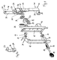
- the retractable closure shown in the drawing consists of a recess in a door opening of a non-illustrated door of a cabinet not shown and to be defined on the door panel 10, on its outside of the door leaf side disposed a recess 11 for receiving a retractable lever handle 12th having.
- the lever handle 12 is mounted on the trough 10 folded out via a pivot bearing 13, wherein in the pivot bearing 13, a spring 14 is integrated, which biases the lever handle 12 in its folded into the recess 11 of the trough 10 position.
- lever handle 12 At its free, in the illustration of Figure 1 lower end of the lever handle 12 is provided with a locking device 15 for locking fixing the lever handle 12 in the recess 11.
- the lever handle 12 at the end a housing 17, in which a means of a key 19 operable cylinder 18 is arranged, which controls the rotational movement of a tongue 20.
- the lever handle 12 is connected to its housing 17 and Tongue 20 in a protruding on the rear side of the trough 10 housing 16 can be folded and locked by means of rotation of the tongue 20 therein.
- a locking rod 22 is slidably disposed, which is guided in a U-shaped rod guide 26, which rod guide 26 by means of a retaining strip 27 form-fitting on the recess 11 facing away from inner surface of the trough 10 is.
- the locking bar 22 carries a protruding arm 23 and has at its upper end a connection structure 24 for attaching a separate rod for locking the cabinet, as such a locking system basically from the EP 0 261 267 B1 is known.
- the locking rod 22 is biased by means of a on a formed on the inside of the trough 10 abutment spring 25 is biased in their marked by the arrow 40 locking position.
- the locking rod 22 is further provided with a perforation 28, in which the teeth of an externally toothed and rotatably mounted on the inside of the trough 10 pinion 29 engage.
- the locking rod 22 with respect to the pinion assembly opposite a second locking bar 30 is slidably mounted in an associated rod guide 26, wherein the external teeth of the pinion 29 engages in a correspondingly formed perforation of the locking bar 30 such that a displacement of the locking bar 22 in a displacement of the locking bar 30 with each opposite direction of movement can be implemented.
- the locking bar 30 also has a connection design 24 in its free end, wherein the locking bar 30 is laterally cranked so that its connection configuration 24 lies in the same plane as the connection configuration of the locking bar 22.
- the locking system is completed by an interposed between the locking bar 22 and the locking bar 30 and in a direction of movement transverse to the direction of displacement of the bars 22, 30 rotatable locking hook 33 which is rotatably supported by means of a pivot bearing 34 on the trough 10. It is a bow spring 35 is provided which biases the locking hook 33 in its locking position, in which the locking hook engages in a conventional manner a cabinet part, preferably a frame part of the door-carrying cabinet in a locking manner.
- the locking hook 33 carries on its side facing the locking rod 22 inside a cam 36 with chamfers 37.
- This cam 36 of the locking hook 33 is assigned to the locking bar 22, a projection 31 formed thereon bevel 32 such that in the locked position of Locking rod 22, the chamfer 32 of the projection 31 and the run-on slope 37 of the cam 36 abut each other, so that a displacement of the locking rod 22 in its release position (arrow 41) causes a pivoting of the locking hook 33 against the action of the bow spring 35 in its release position.
- the lever handle 12 For actuation of the locking system, the lever handle 12 at its end mounted in the pivot bearing 13 a trough 10 by cross and in the retracted position of the pivot lever 12 in the recess 11 of the trough 10 on the arm 23 of the locking bar 22, and that on the direction of movement the latching rod 22 in the locking position (arrow 40) facing side approach 21.
- the projection 21 is arranged so that in the folded position of the lever handle 12, the locking rod 22 biasing spring 25 holds the arm 23 of the locking bar 22 each in abutment against the projection 21.
- the lever handle 12 is pivoted out of the recess 11 of the trough 10 after actuation of the closing device 15.
- the lever handle 12 presses with his neck 21 on the arm 23 of the locking bar 22 and moves it in its release position in Direction arrow 41.
- This movement of the locking rod 22 is simultaneously implemented via the pinion 29 in a corresponding displacement of the locking bar 30, so that the locking bar 30 is moved to its release position (arrow 41).
- the bevel 32 of the attached to the locking bar 22 projection 31 on the run-on slope 37 of the cam 36 of the locking hook 33 so that the locking hook is rotated by the linear displacement of the locking bar 22 in its release position.
- the lever handle 12 After reaching the open position of the lever handle 12 can be released, the lever handle 12 is pivoted back in particular by the spring action of the spring 14 in its folded position in the recess 12 of the trough 10. This movement is assisted by the action of the spring 25 acting on the arm 23 of the locking rod 22, which returns the two rods 22 and 30 to their locking position (arrow 40). Again, the bow spring 35 also pushes the locking hook 33 back into its locking position. Also in this position, the equipped with the retractable closure door can now be closed or thrown because the rods can move regardless of the position of the lever handle in its release position and the locking hook 33 is decoupled from the rod movement and thus independently when closing the door is reciprocable.
Landscapes
- Engineering & Computer Science (AREA)
- Mechanical Engineering (AREA)
- Closing And Opening Devices For Wings, And Checks For Wings (AREA)
- Lock And Its Accessories (AREA)
- Extensible Doors And Revolving Doors (AREA)
Applications Claiming Priority (1)
| Application Number | Priority Date | Filing Date | Title |
|---|---|---|---|
| DE200620014041 DE202006014041U1 (de) | 2006-09-13 | 2006-09-13 | Klapp-Hebelverschluss |
Publications (2)
| Publication Number | Publication Date |
|---|---|
| EP1900891A2 true EP1900891A2 (fr) | 2008-03-19 |
| EP1900891A3 EP1900891A3 (fr) | 2009-04-29 |
Family
ID=37514060
Family Applications (1)
| Application Number | Title | Priority Date | Filing Date |
|---|---|---|---|
| EP20070016619 Withdrawn EP1900891A3 (fr) | 2006-09-13 | 2007-08-24 | Fermeture à levier repliable |
Country Status (3)
| Country | Link |
|---|---|
| US (1) | US7584634B2 (fr) |
| EP (1) | EP1900891A3 (fr) |
| DE (1) | DE202006014041U1 (fr) |
Cited By (2)
| Publication number | Priority date | Publication date | Assignee | Title |
|---|---|---|---|---|
| EP2733286A3 (fr) * | 2012-11-19 | 2016-12-07 | EMKA BESCHLAGTEILE GmbH & Co. KG | Fermeture à levier pivotant ayant une faible profondeur d'intégration |
| DE102017119835A1 (de) | 2017-08-29 | 2019-02-28 | Emka Beschlagteile Gmbh & Co. Kg | Verschlussvorrichtung |
Families Citing this family (9)
| Publication number | Priority date | Publication date | Assignee | Title |
|---|---|---|---|---|
| EP2252750B1 (fr) * | 2008-03-15 | 2013-12-04 | DIRAK Dieter Ramsauer Konstruktionselemente GmbH | Mécanisme à levier pivotant avec dispositif de sécurité |
| DE102010015463B4 (de) * | 2010-04-16 | 2014-08-21 | Emka Beschlagteile Gmbh & Co. Kg | Schwenkhebelverschluss mit Drehverhinderung für die Betätigungswelle |
| FR2969684A1 (fr) * | 2010-12-27 | 2012-06-29 | Ferco Int Usine Ferrures | Dispositif de commande d'une ferrure de verrouillage de type cremone pour un vantail coulissant. |
| DE202012100971U1 (de) | 2012-03-19 | 2012-07-16 | Emka Beschlagteile Gmbh & Co. Kg | Schwenkhebelverschluss mit selbsttätig verrastendem Zylinderschloss |
| US9708833B2 (en) * | 2013-04-09 | 2017-07-18 | Hanchett Entry Systems, Inc. | Swivel lock system with manual override |
| US10422159B2 (en) | 2015-02-23 | 2019-09-24 | Hoffman Enclosures, Inc. | Adjustable rod guide |
| EP3569798B1 (fr) * | 2018-05-16 | 2024-05-29 | Industrilås I Nässjö AB | Agencement de poignée de levage |
| USD980692S1 (en) * | 2022-01-20 | 2023-03-14 | shenzhenshilangtianxiatrading Co,. LTD | Lock |
| US12448823B1 (en) | 2022-11-01 | 2025-10-21 | Global Link Distribution, Corp. | Door handle and locking system |
Family Cites Families (35)
| Publication number | Priority date | Publication date | Assignee | Title |
|---|---|---|---|---|
| US2427386A (en) * | 1944-06-05 | 1947-09-16 | Bassick Co | Door latch |
| US3745796A (en) * | 1971-08-30 | 1973-07-17 | Fleming Metal Fabricators | Lock assembly for metal box |
| US4170119A (en) * | 1978-02-06 | 1979-10-09 | The Scott & Fetzer Company Stahl Division | Paddle handle lock bolt |
| US4510779A (en) * | 1982-07-16 | 1985-04-16 | Adams Rite Products, Inc. | Aircraft door lock actuating mechanism |
| US4554807A (en) * | 1983-10-12 | 1985-11-26 | Ardac, Inc. | Door latch mechanism |
| DE3407700C2 (de) * | 1984-03-02 | 1986-10-30 | Rittal-Werk Rudolf Loh Gmbh & Co Kg, 6348 Herborn | Abschließbare Handhabe für Schaltschranktüren und dgl. |
| DE3676823D1 (de) * | 1986-09-25 | 1991-02-14 | Dieter Ramsauer | Stangenverschluss fuer blechschranktueren. |
| EP0261266B1 (fr) * | 1986-09-25 | 1990-08-22 | Dieter Ramsauer | Fermeture par tringles à poignée basculante |
| JPH0667742U (ja) * | 1993-03-01 | 1994-09-22 | タキゲン製造株式会社 | 埋め込みハンドル装置 |
| US5058937A (en) * | 1991-02-14 | 1991-10-22 | Tri/Mark Corporation | Flush door latch assembly |
| DE59303091D1 (de) * | 1992-12-22 | 1996-08-01 | Knuerr Mechanik Ag | Verschlussvorrichtung für türen von gehäusen oder schränken |
| WO1994015049A1 (fr) * | 1992-12-22 | 1994-07-07 | Dieter Ramsauer | Dispositif de fermeture pour portes de boitiers ou de placards |
| US5970757A (en) * | 1992-12-22 | 1999-10-26 | Ramsauer; Dieter | Swivel lever closing device for doors of housing or cabinets |
| JPH06264655A (ja) * | 1993-03-11 | 1994-09-20 | Takigen Seizo Kk | 引出し回転型扉用ロックハンドル装置 |
| IT230668Y1 (it) * | 1993-10-25 | 1999-06-09 | Corbin Co | Serratura per l'anta secondaria di porte tagliafuoco |
| DE4425970C1 (de) * | 1994-07-22 | 1995-11-16 | Emka Beschlagteile | Versenkbarer Verschluß für links- und rechts angeschlagene Schaltschranktüren |
| JP2623227B2 (ja) * | 1994-08-12 | 1997-06-25 | タキゲン製造株式会社 | 押釦式平面ハンドル装置 |
| US5862690A (en) * | 1996-10-04 | 1999-01-26 | Hoffman Enclosures, Inc. | Low profile handle |
| DE29705508U1 (de) | 1997-03-27 | 1997-06-12 | Emka Beschlagteile Gmbh & Co. Kg, 42551 Velbert | Hebelverschluß |
| ATE206497T1 (de) * | 1997-03-27 | 2001-10-15 | Emka Beschlagteile | Hebelverschluss |
| DE59805806D1 (de) * | 1997-04-02 | 2002-11-07 | Emka Beschlagteile | Modularer stangenverschluss |
| DE29711740U1 (de) * | 1997-07-04 | 1998-11-05 | Ramsauer, Dieter, 42555 Velbert | Durch Vorhängeschloß sichtbare Schwenkhebelbetätigung für den Verschluß von Schaltschranktüren o.dgl. |
| DE29711737U1 (de) * | 1997-07-04 | 1998-10-29 | Ramsauer, Dieter, 42555 Velbert | Durch Vorhängeschloß sichtbare Schwenkhebelbetätigung für den Verschluß von Schaltschranktüren o.dgl. |
| DE29711741U1 (de) * | 1997-07-04 | 1998-11-05 | Ramsauer, Dieter, 42555 Velbert | In eingeschwenktem Zustand sicherbare Schwenkhebelbetätigung für den Verschluß von Schaltschranktüren o.dgl. |
| JP4052796B2 (ja) * | 1997-08-29 | 2008-02-27 | ラムザウアー ディーター | 水平作動式閉鎖装置 |
| DE29722000U1 (de) * | 1997-12-15 | 1999-04-15 | Ramsauer, Dieter, 42555 Velbert | Schwenkhebelverschluß für die Tür, Seitenwand o.dgl. eines Schaltschrankes, einer Maschinenverkleidung oder ähnlichem, mit durch Vorhängeschloß und/oder Haken arretierbarem Schwenkhebel |
| JP2969119B1 (ja) * | 1998-12-22 | 1999-11-02 | タキゲン製造株式会社 | 引き出し回転操作型扉用ロックハンドル装置 |
| AU719207B3 (en) * | 1999-07-16 | 2000-05-04 | Lockwood Security Products Pty Limited | A lock for a sliding window |
| DE29917091U1 (de) * | 1999-09-29 | 2001-02-15 | Ramsauer, Dieter, 42555 Velbert | Griffhebelverschluß zur Montage in einem rechteckigen Durchbruch in einer dünnen Wand, wie Blechschranktür |
| DE20019113U1 (de) * | 2000-11-13 | 2002-04-18 | Ramsauer, Dieter, 42555 Velbert | Hebelverschluß |
| DE20107170U1 (de) * | 2001-04-26 | 2002-08-29 | Ramsauer, Dieter, 42555 Velbert | Stangenschloß mit Hebelantrieb |
| JP3522715B2 (ja) * | 2001-06-08 | 2004-04-26 | タキゲン製造株式会社 | 符号合わせ錠組込み型扉用ロックハンドル装置 |
| US7695028B2 (en) * | 2002-11-07 | 2010-04-13 | Piolax, Inc. | Lock apparatus |
| US7152893B2 (en) * | 2004-08-23 | 2006-12-26 | Key Plastics, Llc | Handle assembly with dual latch feature |
| US7159909B1 (en) * | 2005-11-04 | 2007-01-09 | Kuo-Chuan Hung | Cabinet enclosure handle |
-
2006
- 2006-09-13 DE DE200620014041 patent/DE202006014041U1/de not_active Expired - Lifetime
-
2007
- 2007-08-24 EP EP20070016619 patent/EP1900891A3/fr not_active Withdrawn
- 2007-09-13 US US11/855,074 patent/US7584634B2/en not_active Expired - Fee Related
Cited By (2)
| Publication number | Priority date | Publication date | Assignee | Title |
|---|---|---|---|---|
| EP2733286A3 (fr) * | 2012-11-19 | 2016-12-07 | EMKA BESCHLAGTEILE GmbH & Co. KG | Fermeture à levier pivotant ayant une faible profondeur d'intégration |
| DE102017119835A1 (de) | 2017-08-29 | 2019-02-28 | Emka Beschlagteile Gmbh & Co. Kg | Verschlussvorrichtung |
Also Published As
| Publication number | Publication date |
|---|---|
| US7584634B2 (en) | 2009-09-08 |
| US20080060392A1 (en) | 2008-03-13 |
| DE202006014041U1 (de) | 2006-11-23 |
| EP1900891A3 (fr) | 2009-04-29 |
Similar Documents
| Publication | Publication Date | Title |
|---|---|---|
| DE2611359C2 (de) | Treibstangenverschluß für Türflügel | |
| DE4425970C1 (de) | Versenkbarer Verschluß für links- und rechts angeschlagene Schaltschranktüren | |
| EP0156379B1 (fr) | Tiroir-caisse pour une caisse enregistreuse | |
| DE102013104078B4 (de) | Riegelschloss eines Möbels | |
| DE3645256C2 (de) | Fenster- und Türbeschlag | |
| DE9104553U1 (de) | Mehrriegel-Türschloß | |
| DE202006014041U1 (de) | Klapp-Hebelverschluss | |
| EP2733286B1 (fr) | Fermeture à levier pivotant ayant une faible profondeur d'intégration | |
| EP1917413B1 (fr) | Dispositif de fermeture pour realiser le verrouillage multipoint de portes ou de parties de paroi dans des boitiers ou des armoires | |
| DE102015000606A1 (de) | Verriegelungsvorrichtung für einen schwenkbar gelagerten Flügel | |
| AT513470B1 (de) | Türschloss | |
| DE202011000675U1 (de) | Schrank, insbesondere Gasflaschenschrank | |
| EP1739260B1 (fr) | Transmission d'une ferrure pour fenêtre, portes, ou similaire, et procédé pour actionner la transmission | |
| EP3118401A1 (fr) | Verrour pour le chant d'un battant | |
| WO2010115544A1 (fr) | Fermeture à levier avec entraînement frontal de ses tiges de verrouillage | |
| EP1970513B1 (fr) | Semi-fixe d'une porte à deux battants et dispositif de fermeture | |
| DE102016112554A1 (de) | Anordnung mit einem Blendrahmen zur Lagerung eines Flügelrahmens | |
| AT413044B (de) | Haltevorrichtung für eine schubstange oder einen schubstangenschieber eines mehrriegelschlosses | |
| EP0913546B1 (fr) | Ferrure pour le mécanisme de commande du vantail d'une porte ou d'une fenêtre | |
| EP0199270A2 (fr) | Dispositif pour maintenir une porte ou une fenêtre entrouverte dans au moins une position | |
| DE29818045U1 (de) | Beschlag für Klappfenster, insbesondere von Wohnwagen, Mobilheimen u.dgl. | |
| EP1936078A2 (fr) | Garniture de fermeture antipanique | |
| EP1790805B1 (fr) | Mécanisme d'actionnement à levier pour une crémone | |
| WO2012119721A2 (fr) | Serrure de meuble | |
| DE10200113B4 (de) | Türschloss |
Legal Events
| Date | Code | Title | Description |
|---|---|---|---|
| PUAI | Public reference made under article 153(3) epc to a published international application that has entered the european phase |
Free format text: ORIGINAL CODE: 0009012 |
|
| AK | Designated contracting states |
Kind code of ref document: A2 Designated state(s): AT BE BG CH CY CZ DE DK EE ES FI FR GB GR HU IE IS IT LI LT LU LV MC MT NL PL PT RO SE SI SK TR |
|
| AX | Request for extension of the european patent |
Extension state: AL BA HR MK YU |
|
| PUAL | Search report despatched |
Free format text: ORIGINAL CODE: 0009013 |
|
| AK | Designated contracting states |
Kind code of ref document: A3 Designated state(s): AT BE BG CH CY CZ DE DK EE ES FI FR GB GR HU IE IS IT LI LT LU LV MC MT NL PL PT RO SE SI SK TR |
|
| AX | Request for extension of the european patent |
Extension state: AL BA HR MK RS |
|
| AKX | Designation fees paid | ||
| STAA | Information on the status of an ep patent application or granted ep patent |
Free format text: STATUS: THE APPLICATION IS DEEMED TO BE WITHDRAWN |
|
| 18D | Application deemed to be withdrawn |
Effective date: 20091030 |
|
| REG | Reference to a national code |
Ref country code: DE Ref legal event code: 8566 |