EP1900895A2 - Dispositif de fixation pour la fixation amovible de vantaux de porte ouverts se fermant automatiquement - Google Patents
Dispositif de fixation pour la fixation amovible de vantaux de porte ouverts se fermant automatiquement Download PDFInfo
- Publication number
- EP1900895A2 EP1900895A2 EP07017048A EP07017048A EP1900895A2 EP 1900895 A2 EP1900895 A2 EP 1900895A2 EP 07017048 A EP07017048 A EP 07017048A EP 07017048 A EP07017048 A EP 07017048A EP 1900895 A2 EP1900895 A2 EP 1900895A2
- Authority
- EP
- European Patent Office
- Prior art keywords
- cylinder
- piston
- locking device
- locking pin
- pin
- Prior art date
- Legal status (The legal status is an assumption and is not a legal conclusion. Google has not performed a legal analysis and makes no representation as to the accuracy of the status listed.)
- Withdrawn
Links
Images

Classifications
-
- E—FIXED CONSTRUCTIONS
- E05—LOCKS; KEYS; WINDOW OR DOOR FITTINGS; SAFES
- E05C—BOLTS OR FASTENING DEVICES FOR WINGS, SPECIALLY FOR DOORS OR WINDOWS
- E05C17/00—Devices for holding wings open; Devices for limiting opening of wings or for holding wings open by a movable member extending between frame and wing; Braking devices, stops or buffers, combined therewith
- E05C17/02—Devices for holding wings open; Devices for limiting opening of wings or for holding wings open by a movable member extending between frame and wing; Braking devices, stops or buffers, combined therewith by mechanical means
- E05C17/44—Devices for holding wings open; Devices for limiting opening of wings or for holding wings open by a movable member extending between frame and wing; Braking devices, stops or buffers, combined therewith by mechanical means with a device carried on the wing for frictional or like engagement with a fixed flat surface, e.g. for holding wings open or closed by retractable feet
- E05C17/446—Devices for holding wings open; Devices for limiting opening of wings or for holding wings open by a movable member extending between frame and wing; Braking devices, stops or buffers, combined therewith by mechanical means with a device carried on the wing for frictional or like engagement with a fixed flat surface, e.g. for holding wings open or closed by retractable feet of the retractable sliding feet type
Definitions
- the invention relates to a locking device for releasably fixing open, automatically in the closed position zu fallender door leaves, in particular fire protection door leaves according to the preamble of the independent claims 1 and 2.
- Locking devices of this type are generally known as so-called door lock and usually fixed at the bottom of a door leaf and require in subsequently szuhaltendem and automatically in the closed position going door leaf only a depressing example. Foot load to clamp the locking pin of the device with locking against the ground and also to solve this again.
- This also applies to a door lock after the DE 29701673 U1 in which for the door leaf fixing a guided in a housing, spring-loaded plunger is provided, which is held by depressing by foot in clamping position to the ground by a pin penetrated by the pin grip plate, their targeted load also on foot, the clamping position dissolves again and thus the Door is released again.
- Another door locker after the KR 1005 38464 B1 differs from the aforementioned lock in that arranged in a hydraulic cylinder, a double-acting piston with locking pin and the hydraulic cylinder is associated with a hydraulic pump, with, by means of a switch, the up and down movement of only one side out of the cylinder downwardly protruding locking ram regulated and thus the determination or solution of the plunger is effected with respect to the ground.
- a momentary and targeted release of the locking ram are effected.
- the invention has the object of reshaping and improving a locking device of the type mentioned in that it releases the passage closure or the door leaf automatically closing to fulfill particular fire protection requirements after passage.
- the two independent solutions have their reason alone in that with the same design of the cylinder and the pin / piston unit therein different conditions may exist with respect to the abutment, namely insofar as on the one hand, the abutment is formed by the floor extending in the door itself and the Others installed by a wall or wall on the floor or a wall adjacent to the pivoting area of the door wall counter-holder, which in this case so belongs to the device. It should be noted in both cases that despite onset of restoring movement of the locking pin this maintains its blocking contact in the first case to the ground and in the second case to the counter-holder over a certain time thanks to its inventive design. In the following, reference will first be made to the preferred embodiment, in which the fixing of the door leaf takes place against the floor.
- the locking device according to the invention after the first solution is designed such that the locking pin that with an incompressible
- the cylinder filled with medium filled sealingly penetrates at both ends and the locking pin inside the cylinder is provided with a piston.
- the cylinder forms the device housing provided with fastening elements.
- the piston has a check valve and a flow channel connecting the first and second cylinder interiors, wherein both cylinder interiors are connected to a bypass channel emanating from their end regions, in which a flow-through throttle forming the trigger element is arranged.
- This configuration of the cylinder applies in this respect also for the second solution.
- the bottom support side end of the locking pin standing under spring tension, while the locking pin axially displaceable associated.
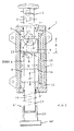
- the locking device which is intended in particular for fire doors, but of course can come to other doors for use, consists in a known manner from a cylinder 1 against a stationary abutment W for blocking effect and releasable by means of a trigger element Matblattfestellzapfen 4, with a forms on both sides by means of an incompressible medium piston 5 a displaceable in the cylinder 1 pin / piston unit ZKE forms.
- the incompressible medium hydroaulic oil
- the throttle 11 conditionally interrupted circular system, which cooperates with the arranged at the upper end of the locking pin 4 return spring 2 and thus with a lower spring with respect to the spring 2 set lower spring 17, which holds a lower end 4 'of the locking pin 4 forming and axially displaceable sleeve 16 as long as against the ground until the adjustable by means of the throttle 11 time delay has expired or the locking pin has returned so far that the sleeve 16 of Floor is lifted and the door leaf can automatically go back to the closed position.
- the lower end 4 'of the locking pin 4 also spring-loaded, could also be formed telescopically or even as a spring with suitable base plate BP.
- the bypass channel 10 is arranged in the cylinder wall 1 'and is simply represented by a longitudinal bore to be introduced axially parallel, in its lower end region the fürströmdrossel 11, as shown in a highly schematic, is arranged.
- This arrangement region of the throttle 11 must of course be formed to the outside pressure and liquid-tight, and, since the flow restrictor 11 should also be adjusted appropriately, this seal must also be designed so that the throttle 11 is adjustable from the outside, which is not particularly illustrated , as there are various design options (eg., Covering the arrangement area of the throttle or, for example, stuffing box bearing of the throttle element).
- the piston 5 is, as shown, dimensioned with a height H which substantially corresponds to its diameter D, wherein the bypass passage 10 with an unthrottled channel 14 communicates with the cylinder interior I and the channel 14 to the arrangement region of the flow restrictor 11 substantially one of the piston height H corresponding distance D is arranged.
- the bypass passage 10 with an unthrottled channel 14 communicates with the cylinder interior I and the channel 14 to the arrangement region of the flow restrictor 11 substantially one of the piston height H corresponding distance D is arranged.
- the service side part 3 of the locking pin 4 can be formed as a separate part with the piston 5 in the region of the check valve seat 6 'connectable.
- abutment 18 forming the abutment W it is, as shown, for example, formed from a roller 20 mounted in a bracket 19.
- the bracket 19 attached to the door leaf TB can be correspondingly aligned with the wall, as shown, a rubber buffer 22 assigned.
- the embodiment according to FIG. 2 is therefore an automatically time-delayed resetting latch.
- an arrangement as shown near the ground is not mandatory, that is, an arrangement, for example, in the area of the door lock can also be considered.
- the upper end 3 of the locking pin 4 can also be provided with a more or less long lever 21 in the context of FIG if this should require access.
Landscapes
- Engineering & Computer Science (AREA)
- Mechanical Engineering (AREA)
- Closing And Opening Devices For Wings, And Checks For Wings (AREA)
- Special Wing (AREA)
Applications Claiming Priority (1)
| Application Number | Priority Date | Filing Date | Title |
|---|---|---|---|
| DE200610042425 DE102006042425B4 (de) | 2006-09-09 | 2006-09-09 | Türfeststeller |
Publications (2)
| Publication Number | Publication Date |
|---|---|
| EP1900895A2 true EP1900895A2 (fr) | 2008-03-19 |
| EP1900895A3 EP1900895A3 (fr) | 2008-05-07 |
Family
ID=38787657
Family Applications (1)
| Application Number | Title | Priority Date | Filing Date |
|---|---|---|---|
| EP07017048A Withdrawn EP1900895A3 (fr) | 2006-09-09 | 2007-08-31 | Dispositif de fixation pour la fixation amovible de vantaux de porte ouverts se fermant automatiquement |
Country Status (2)
| Country | Link |
|---|---|
| EP (1) | EP1900895A3 (fr) |
| DE (1) | DE102006042425B4 (fr) |
Cited By (3)
| Publication number | Priority date | Publication date | Assignee | Title |
|---|---|---|---|---|
| CN112004982A (zh) * | 2018-05-25 | 2020-11-27 | 三井金属爱科特株式会社 | 汽车用车门开度限位装置 |
| CN112384672A (zh) * | 2018-07-11 | 2021-02-19 | 宁波吉利汽车研究开发有限公司 | 车门定位保持器 |
| US20240410209A1 (en) * | 2023-06-09 | 2024-12-12 | JOHN B CARBER, Sr. | Gate support system |
Families Citing this family (3)
| Publication number | Priority date | Publication date | Assignee | Title |
|---|---|---|---|---|
| DE202011050866U1 (de) | 2011-07-29 | 2011-09-07 | Helmut Fischer GmbH Institut für Elektronik und Messtechnik | Türfeststeller, insbesondere Türfeststeller für eine Brandschutztür |
| CN110195537B (zh) * | 2018-01-09 | 2020-07-07 | 北京半导体专用设备研究所(中国电子科技集团公司第四十五研究所) | 真空吸附门吸装置 |
| CN113846918A (zh) * | 2021-09-09 | 2021-12-28 | 陈安 | 一种外开门用便携阻门器 |
Family Cites Families (6)
| Publication number | Priority date | Publication date | Assignee | Title |
|---|---|---|---|---|
| FI23823A (fi) * | 1948-09-21 | 1949-07-09 | Ovenpidin | |
| DE2151336A1 (de) * | 1971-10-15 | 1973-04-19 | Mecanismos Y Accesorios S A | Hydraulischer daempfer, insbesondere fuer tuerschliesser |
| US4050723A (en) * | 1976-05-17 | 1977-09-27 | George Papadatos | Mechanism for securing a door in open or closed position |
| WO1998020223A1 (fr) * | 1995-10-27 | 1998-05-14 | Karlquist Per Erik | Dispositif de piston |
| DE29701673U1 (de) * | 1997-01-31 | 1998-05-28 | Niederhoff & Dellenbusch GmbH & Co, 42579 Heiligenhaus | Türfeststeller |
| KR100538464B1 (ko) * | 2005-09-13 | 2005-12-22 | 신성종합건축사사무소(주) | 건축용 문의 열림 각도 고정장치 |
-
2006
- 2006-09-09 DE DE200610042425 patent/DE102006042425B4/de not_active Expired - Fee Related
-
2007
- 2007-08-31 EP EP07017048A patent/EP1900895A3/fr not_active Withdrawn
Cited By (3)
| Publication number | Priority date | Publication date | Assignee | Title |
|---|---|---|---|---|
| CN112004982A (zh) * | 2018-05-25 | 2020-11-27 | 三井金属爱科特株式会社 | 汽车用车门开度限位装置 |
| CN112384672A (zh) * | 2018-07-11 | 2021-02-19 | 宁波吉利汽车研究开发有限公司 | 车门定位保持器 |
| US20240410209A1 (en) * | 2023-06-09 | 2024-12-12 | JOHN B CARBER, Sr. | Gate support system |
Also Published As
| Publication number | Publication date |
|---|---|
| EP1900895A3 (fr) | 2008-05-07 |
| DE102006042425A1 (de) | 2008-03-27 |
| DE102006042425B4 (de) | 2008-09-04 |
Similar Documents
| Publication | Publication Date | Title |
|---|---|---|
| DE3001406A1 (de) | Selbsttaetiger tuerschliesser | |
| EP1900895A2 (fr) | Dispositif de fixation pour la fixation amovible de vantaux de porte ouverts se fermant automatiquement | |
| EP3417134B1 (fr) | Ensemble ferrure pour le raccordement d'un battant coulissant et basculant | |
| EP2529137B1 (fr) | Soupape de limitation de pression | |
| DE102011006011A1 (de) | Fahrzeug | |
| DE19517442B4 (de) | Verschluß für Öffnungen abdeckende Klappen in Fahrzeugen, insbesondere Handschuhkasten-Verschluß | |
| EP3109385B1 (fr) | Dispositif de fermeture de porte comprenant un battant de porte unique ou en plusieurs parties | |
| DE202018104869U1 (de) | System für die Steuerung der Schließreihenfolge von zweiflügeligen Türen | |
| DE102008063765A1 (de) | Schiebetürsystem | |
| WO2015010672A1 (fr) | Dispositif permettant de déclencher un ressort à gaz | |
| DE102005005891B4 (de) | Tür mit Türbremse | |
| DE19948579C2 (de) | Pendeltür für Durchgangsanlagen | |
| DE10361085B4 (de) | Hydraulisch-mechanische Schließfolgeregelung | |
| DE202013006581U1 (de) | Vorrichtung zum Auslösen einer Gasfeder | |
| DE1953116U (de) | Vorrichtung zum halten und feststellen einer fahrzeugschiebetuere. | |
| WO2010115544A1 (fr) | Fermeture à levier avec entraînement frontal de ses tiges de verrouillage | |
| DE102008035769C5 (de) | Fahrzeugaufbau für Nutzfahrzeuge | |
| DE20307840U1 (de) | Notentriegelungsvorrichtung an einer Schwenkschiebetür für Fahrzeuge, insbesondere Fahrzeuge des öffentlichen Personennahverkehrs | |
| EP2896773B1 (fr) | Régulation de la séquence de fermeture | |
| DE102013022158B3 (de) | Türschließer | |
| DE3912740C1 (en) | Safety fitting self-closing doors and windows - has hydraulic damping cylinder for door etc. closing mechanism, with locking member coupled to transfer element | |
| DE4413560C2 (de) | Hydraulik-Steuervorrichtung für Rettungsgeräte | |
| DE102004036773B4 (de) | Vorrichtung zur Befestigung von Lademodulen in einem Laderaum | |
| DE102004032157A1 (de) | Verschluss für Türen oder Klappen an Fahrzeugen | |
| EP1620626B2 (fr) | Sequence de fermeture mecano-hydraulique |
Legal Events
| Date | Code | Title | Description |
|---|---|---|---|
| PUAI | Public reference made under article 153(3) epc to a published international application that has entered the european phase |
Free format text: ORIGINAL CODE: 0009012 |
|
| AK | Designated contracting states |
Kind code of ref document: A2 Designated state(s): AT BE BG CH CY CZ DE DK EE ES FI FR GB GR HU IE IS IT LI LT LU LV MC MT NL PL PT RO SE SI SK TR |
|
| AX | Request for extension of the european patent |
Extension state: AL BA HR MK YU |
|
| PUAL | Search report despatched |
Free format text: ORIGINAL CODE: 0009013 |
|
| AK | Designated contracting states |
Kind code of ref document: A3 Designated state(s): AT BE BG CH CY CZ DE DK EE ES FI FR GB GR HU IE IS IT LI LT LU LV MC MT NL PL PT RO SE SI SK TR |
|
| AX | Request for extension of the european patent |
Extension state: AL BA HR MK RS |
|
| RIC1 | Information provided on ipc code assigned before grant |
Ipc: E05C 17/30 20060101ALI20080402BHEP Ipc: E05C 17/44 20060101AFI20071218BHEP |
|
| 17P | Request for examination filed |
Effective date: 20081024 |
|
| 17Q | First examination report despatched |
Effective date: 20081120 |
|
| AKX | Designation fees paid |
Designated state(s): AT BE BG CH CY CZ DE DK EE ES FI FR GB GR HU IE IS IT LI LT LU LV MC MT NL PL PT RO SE SI SK TR |
|
| GRAP | Despatch of communication of intention to grant a patent |
Free format text: ORIGINAL CODE: EPIDOSNIGR1 |
|
| STAA | Information on the status of an ep patent application or granted ep patent |
Free format text: STATUS: THE APPLICATION IS DEEMED TO BE WITHDRAWN |
|
| 18D | Application deemed to be withdrawn |
Effective date: 20091117 |