EP1900905A2 - Gestion thermique de surface portante dotée de refroidissement de microcircuit - Google Patents
Gestion thermique de surface portante dotée de refroidissement de microcircuit Download PDFInfo
- Publication number
- EP1900905A2 EP1900905A2 EP07253638A EP07253638A EP1900905A2 EP 1900905 A2 EP1900905 A2 EP 1900905A2 EP 07253638 A EP07253638 A EP 07253638A EP 07253638 A EP07253638 A EP 07253638A EP 1900905 A2 EP1900905 A2 EP 1900905A2
- Authority
- EP
- European Patent Office
- Prior art keywords
- cooling
- cooling circuit
- side wall
- turbine engine
- engine component
- Prior art date
- Legal status (The legal status is an assumption and is not a legal conclusion. Google has not performed a legal analysis and makes no representation as to the accuracy of the status listed.)
- Granted
Links
Images
Classifications
-
- F—MECHANICAL ENGINEERING; LIGHTING; HEATING; WEAPONS; BLASTING
- F01—MACHINES OR ENGINES IN GENERAL; ENGINE PLANTS IN GENERAL; STEAM ENGINES
- F01D—NON-POSITIVE DISPLACEMENT MACHINES OR ENGINES, e.g. STEAM TURBINES
- F01D5/00—Blades; Blade-carrying members; Heating, heat-insulating, cooling or antivibration means on the blades or the members
- F01D5/12—Blades
- F01D5/14—Form or construction
- F01D5/18—Hollow blades, i.e. blades with cooling or heating channels or cavities; Heating, heat-insulating or cooling means on blades
- F01D5/187—Convection cooling
-
- F—MECHANICAL ENGINEERING; LIGHTING; HEATING; WEAPONS; BLASTING
- F05—INDEXING SCHEMES RELATING TO ENGINES OR PUMPS IN VARIOUS SUBCLASSES OF CLASSES F01-F04
- F05D—INDEXING SCHEME FOR ASPECTS RELATING TO NON-POSITIVE-DISPLACEMENT MACHINES OR ENGINES, GAS-TURBINES OR JET-PROPULSION PLANTS
- F05D2260/00—Function
- F05D2260/20—Heat transfer, e.g. cooling
- F05D2260/221—Improvement of heat transfer
- F05D2260/2214—Improvement of heat transfer by increasing the heat transfer surface
Definitions
- the present invention relates to a cooling arrangement for use in a turbine engine component.
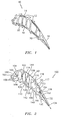
- FIG. 1 illustrates a current cooling scheme for a turbine blade 10. It consists of a hybrid application of embedded microcircuit panels 12 running axially along the airfoil walls 14 and 16 in combination with a set of film cooling holes.
- the airfoil active convective cooling is done through a series of microcircuits 12 in the mid-body and trailing edge portions of the airfoil 18, supplemented with film cooling by a series of film holes 20.
- the axial circuits do not take full advantage of pumping; therefore, dedicated feed cavities are used for independently feeding each circuit. This leads to an increased number of airfoil ribs 22.
- the airfoil outer layers experience relatively hot metal temperatures. If the temperature is sufficiently high, a stress relaxation process occurs at these airfoil locations, leading to relatively high strains (deformations). Simultaneously, the relative cold inside ribs 22 experience an increase in stress as the load to the part needs to be shared by the entire airfoil 18. This balance in the stress-state of the airfoil occurs every time a blade is ramped up, causing some amount of irreversible damage, which, in excessive limits, can lead to catastrophic failures. If these limits are not approached, the amount of damage accumulation can take some time or cycles. That is, long enough to make the design viable for the require life targets.
- the present invention relates to a cooling scheme for a turbine engine component, such as a turbine blade, which reduces the outer metal temperatures and the thermal gradients in the part.
- a turbine engine component which broadly comprises an airfoil portion having a pressure side wall and a suction side wall, a plurality of ribs extending between said pressure side wall and said suction side wall, and a plurality of supply cavities located between said ribs; and an arrangement for cooling said airfoil portion comprising a first means embedded within said suction side wall for convectively cooling said suction side wall, a second means embedded within said pressure side wall for cooling said pressure side wall, and third means for increasing a temperature of at least one said ribs by conduction.
- a process for cooling a turbine engine component broadly comprising the steps of: providing a first cooling circuit in a suction side of an airfoil portion of said turbine engine component; providing a second cooling circuit in a pressure side of said airfoil portion; convectively cooling said suction side of said airfoil portion with said first cooling circuit; and heating a rib within said airfoil portion using cooling fluid leaving said first cooling circuit.
- FIG. 2 there is shown a turbine engine component 100, such as a turbine blade, with a different set of microcircuits 101 and 102 embedded in the walls and ribs of the airfoil portion 104.
- the airfoil portion 104 includes a pressure side wall 106 and a suction side wall 108.
- the airfoil portion 104 also includes a plurality of ribs 110.
- peripheral cooling with microcircuits embedded within the walls 106 and 108 is used.
- the cooling scheme of the present invention takes advantage of pumping, and the thermal stress, due to large temperature differences, should be minimized.
- the cooling scheme of the present invention includes suction side cooling microcircuits 101 and 102 embedded within the suction side wall 108.
- the circuit 101 has a flow inlet 116, while the circuit 102 has a flow inlet 118.
- the flow inlet 116 is located at a root section of the turbine engine component 100 for pumping.
- the flow inlet 118 is also located at the root section of the turbine engine component 100.
- Each of the flow inlets 116 and 118 communicate with a source of cooling fluid, such as engine bleed air, flowing through the supply cavity 120.
- the cooling circuits 101 and 102 have no film holes which would allow cooling fluid to flow over the exterior surface of the suction side 108 of the airfoil portion 104.
- the suction side 108 is cooled solely by convection.
- the cooling circuit 101 has a cooling circuit 114 embedded within the suction side wall 108. Cooling fluid flows from the cooling circuit 114 to the pressure side 106 of the airfoil portion 104 via one or more passageways 122 in a first of the ribs 110. Each passageway 122 connects the cooling circuit 114 with a cooling circuit 124 embedded within the pressure side wall 106.
- the cooling circuit 124 has one or more film cooling holes 126 which allow the cooling fluid to flow over the pressure side wall 106.
- the cooling circuit 102 has a cooling circuit 117 embedded within the suction side wall 108.
- the cooling circuit 117 communicates with one or more passageways 128 in a second one of the ribs 110.
- Each passageway 128 communicates with a second cooling circuit 130 embedded in the pressure side wall 106, which circuit 130 has one or more film cooling holes 132 for allowing a film of cooling fluid to flow over a portion of the pressure side wall 106 adjacent a trailing edge 134 of the airfoil portion 104.
- a third cooling circuit 140 may be embedded in the pressure side wall 106.
- the third cooling circuit 140 has an inlet 142 also located at the root section of the turbine engine component 100 for pumping.
- the inlet 142 communicates with a source of cooling fluid via the supply cavity 144.
- the circuit 140 also may have one or more film cooling holes 146 for allowing cooling fluid to flow over the external surface of the pressure side wall 106.
- cooling fluid from a cavity 150 may pass through a trailing edge cooling circuit 152 via one or more cross over holes 154 in a most rearward one of the ribs 110.
- cooling fluid may be provided to a leading edge cooling cavity 162 from a supply cavity 164 via one or more cross over holes 166 in a most forward one of the ribs 110.
- the leading edge cooling cavity 162 may have one or more fluid outlets 168 in the leading edge 160 to allow cooling fluid to flow over the leading edge portion of the pressure side wall 106 and the suction side wall 108.
- each of the cooling circuits embedded in the pressure and suction side walls 106 and 108 may have a plurality of pedestals 170 for enhancing heat transfer.
- the pedestals 170 may have any desired shape such as a cylindrical shape.
- the cooling scheme of the present invention has a feed which starts at the suction side of the airfoil portion 104, particularly at the root section. The flow is guided through the suction side of the airfoil, picking up heat in that section of the airfoil.
- the cooling circuit in the suction side would end, also at the suction side, by allowing film cooling to eject externally out of the circuit. This has the advantage of film protection at the suction side, but also causes mixing and entropy, which affects performance negatively.
- the circuit does not end in film cooling, but proceeds through the internal ribs 110 towards the pressure side 106.
- the net effect of this is to increase the temperature of the ribs 110 through conduction.
- the third leg of the circuit is formed to transport the coolant through the pressure side wall 106 of the airfoil portion 104, discharging with film cooling at the pressure side.
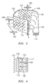
- FIG. 3 there is shown a series of heat balance control volumes 180 which illustrate the concept of picking-up heat at the suction side first; dissipating the heat through the rib; and picking-up heat once again at the pressure side, ending the circuit with film cooling at the pressure side.
- the following targets are accomplished: (1) a reduction in creep damage with peripheral microcircuit cooling; (2) an enhancement of the heat pick-up by taking advantage of a natural rotational pumping action; (3) a reduction in overall thermal gradients by increasing the internal rib temperatures; (4) an increase in the convective efficiency of the microcircuits by allowing a continued cooling capability on the opposite side of the airfoil portion; and (5) a film cooling of the pressure side with a circuit that starts at the suction side, thus eliminating aerodynamic losses in the suction side of the airfoil portion 104.
Landscapes
- Engineering & Computer Science (AREA)
- Mechanical Engineering (AREA)
- General Engineering & Computer Science (AREA)
- Turbine Rotor Nozzle Sealing (AREA)
Applications Claiming Priority (1)
| Application Number | Priority Date | Filing Date | Title |
|---|---|---|---|
| US11/520,374 US7625179B2 (en) | 2006-09-13 | 2006-09-13 | Airfoil thermal management with microcircuit cooling |
Publications (3)
| Publication Number | Publication Date |
|---|---|
| EP1900905A2 true EP1900905A2 (fr) | 2008-03-19 |
| EP1900905A3 EP1900905A3 (fr) | 2011-06-22 |
| EP1900905B1 EP1900905B1 (fr) | 2012-12-05 |
Family
ID=38616560
Family Applications (1)
| Application Number | Title | Priority Date | Filing Date |
|---|---|---|---|
| EP07253638A Ceased EP1900905B1 (fr) | 2006-09-13 | 2007-09-13 | Gestion thermique d'une aube avec refroidissement par microcircuit |
Country Status (2)
| Country | Link |
|---|---|
| US (1) | US7625179B2 (fr) |
| EP (1) | EP1900905B1 (fr) |
Cited By (2)
| Publication number | Priority date | Publication date | Assignee | Title |
|---|---|---|---|---|
| EP2631431A1 (fr) * | 2011-11-24 | 2013-08-28 | Rolls-Royce plc | Agencement de refroidissement de surface portante |
| EP3165715A1 (fr) * | 2015-10-15 | 2017-05-10 | General Electric Company | Aube de turbine |
Families Citing this family (5)
| Publication number | Priority date | Publication date | Assignee | Title |
|---|---|---|---|---|
| US7857589B1 (en) * | 2007-09-21 | 2010-12-28 | Florida Turbine Technologies, Inc. | Turbine airfoil with near-wall cooling |
| US8562286B2 (en) | 2010-04-06 | 2013-10-22 | United Technologies Corporation | Dead ended bulbed rib geometry for a gas turbine engine |
| US9353631B2 (en) | 2011-08-22 | 2016-05-31 | United Technologies Corporation | Gas turbine engine airfoil baffle |
| US10174620B2 (en) | 2015-10-15 | 2019-01-08 | General Electric Company | Turbine blade |
| DE102019125779B4 (de) * | 2019-09-25 | 2024-03-21 | Man Energy Solutions Se | Schaufel einer Strömungsmaschine |
Citations (2)
| Publication number | Priority date | Publication date | Assignee | Title |
|---|---|---|---|---|
| GB2246174A (en) | 1982-06-29 | 1992-01-22 | Rolls Royce | Cooled aerofoil for a gas turbine engine |
| US20010018021A1 (en) | 1998-08-31 | 2001-08-30 | Dirk Anding | Turbine blade |
Family Cites Families (6)
| Publication number | Priority date | Publication date | Assignee | Title |
|---|---|---|---|---|
| US6402470B1 (en) * | 1999-10-05 | 2002-06-11 | United Technologies Corporation | Method and apparatus for cooling a wall within a gas turbine engine |
| GB0114503D0 (en) * | 2001-06-14 | 2001-08-08 | Rolls Royce Plc | Air cooled aerofoil |
| US7303376B2 (en) * | 2005-12-02 | 2007-12-04 | Siemens Power Generation, Inc. | Turbine airfoil with outer wall cooling system and inner mid-chord hot gas receiving cavity |
| US7322795B2 (en) * | 2006-01-27 | 2008-01-29 | United Technologies Corporation | Firm cooling method and hole manufacture |
| US7481622B1 (en) * | 2006-06-21 | 2009-01-27 | Florida Turbine Technologies, Inc. | Turbine airfoil with a serpentine flow path |
| US7527474B1 (en) * | 2006-08-11 | 2009-05-05 | Florida Turbine Technologies, Inc. | Turbine airfoil with mini-serpentine cooling passages |
-
2006
- 2006-09-13 US US11/520,374 patent/US7625179B2/en not_active Expired - Fee Related
-
2007
- 2007-09-13 EP EP07253638A patent/EP1900905B1/fr not_active Ceased
Patent Citations (2)
| Publication number | Priority date | Publication date | Assignee | Title |
|---|---|---|---|---|
| GB2246174A (en) | 1982-06-29 | 1992-01-22 | Rolls Royce | Cooled aerofoil for a gas turbine engine |
| US20010018021A1 (en) | 1998-08-31 | 2001-08-30 | Dirk Anding | Turbine blade |
Cited By (3)
| Publication number | Priority date | Publication date | Assignee | Title |
|---|---|---|---|---|
| EP2631431A1 (fr) * | 2011-11-24 | 2013-08-28 | Rolls-Royce plc | Agencement de refroidissement de surface portante |
| US9376918B2 (en) | 2011-11-24 | 2016-06-28 | Rolls-Royce Plc | Aerofoil cooling arrangement |
| EP3165715A1 (fr) * | 2015-10-15 | 2017-05-10 | General Electric Company | Aube de turbine |
Also Published As
| Publication number | Publication date |
|---|---|
| EP1900905A3 (fr) | 2011-06-22 |
| EP1900905B1 (fr) | 2012-12-05 |
| US7625179B2 (en) | 2009-12-01 |
| US20090238675A1 (en) | 2009-09-24 |
Similar Documents
| Publication | Publication Date | Title |
|---|---|---|
| EP1900905B1 (fr) | Gestion thermique d'une aube avec refroidissement par microcircuit | |
| US7513744B2 (en) | Microcircuit cooling and tip blowing | |
| US9051943B2 (en) | Gas turbine engine heat exchanger fins with periodic gaps | |
| US8628298B1 (en) | Turbine rotor blade with serpentine cooling | |
| US8562295B1 (en) | Three piece bonded thin wall cooled blade | |
| US8192146B2 (en) | Turbine blade dual channel cooling system | |
| US9200570B2 (en) | Air-cooled oil cooler for turbofan engine | |
| US8292582B1 (en) | Turbine blade with serpentine flow cooling | |
| EP1900904B1 (fr) | Microcanaux à serpentin multi-périphériques pour aubes à haute performance | |
| US8109726B2 (en) | Turbine blade with micro channel cooling system | |
| US8454301B1 (en) | Turbine blade with serpentine cooling | |
| US7806658B2 (en) | Turbine airfoil cooling system with spanwise equalizer rib | |
| US8025482B1 (en) | Turbine blade with dual serpentine cooling | |
| EP2607624B1 (fr) | Aube statorique pour turbomachine | |
| EP1884621B1 (fr) | Refroidissement par microcircuit à serpentin avec des caractéristiques côtés pression | |
| US8613597B1 (en) | Turbine blade with trailing edge cooling | |
| US8016564B1 (en) | Turbine blade with leading edge impingement cooling | |
| US20170089207A1 (en) | Turbine airfoil cooling system with leading edge impingement cooling system and nearwall impingement system | |
| US7950903B1 (en) | Turbine blade with dual serpentine cooling | |
| US11268443B2 (en) | Turbine engine nacelle comprising a cooling device | |
| EP1882819A1 (fr) | Microcircuits pour pales de turbine intégrés dans la plate-forme, la pointe, et l'aube | |
| US20170370231A1 (en) | Turbine airfoil cooling system with integrated airfoil and platform cooling system | |
| US8267658B1 (en) | Low cooling flow turbine rotor blade | |
| US7988417B1 (en) | Air cooled turbine blade | |
| US8061990B1 (en) | Turbine rotor blade with low cooling flow |
Legal Events
| Date | Code | Title | Description |
|---|---|---|---|
| PUAI | Public reference made under article 153(3) epc to a published international application that has entered the european phase |
Free format text: ORIGINAL CODE: 0009012 |
|
| AK | Designated contracting states |
Kind code of ref document: A2 Designated state(s): AT BE BG CH CY CZ DE DK EE ES FI FR GB GR HU IE IS IT LI LT LU LV MC MT NL PL PT RO SE SI SK TR |
|
| AX | Request for extension of the european patent |
Extension state: AL BA HR MK YU |
|
| PUAL | Search report despatched |
Free format text: ORIGINAL CODE: 0009013 |
|
| AK | Designated contracting states |
Kind code of ref document: A3 Designated state(s): AT BE BG CH CY CZ DE DK EE ES FI FR GB GR HU IE IS IT LI LT LU LV MC MT NL PL PT RO SE SI SK TR |
|
| AX | Request for extension of the european patent |
Extension state: AL BA HR MK RS |
|
| 17P | Request for examination filed |
Effective date: 20111221 |
|
| AKX | Designation fees paid |
Designated state(s): DE GB |
|
| GRAP | Despatch of communication of intention to grant a patent |
Free format text: ORIGINAL CODE: EPIDOSNIGR1 |
|
| GRAS | Grant fee paid |
Free format text: ORIGINAL CODE: EPIDOSNIGR3 |
|
| GRAA | (expected) grant |
Free format text: ORIGINAL CODE: 0009210 |
|
| AK | Designated contracting states |
Kind code of ref document: B1 Designated state(s): DE GB |
|
| REG | Reference to a national code |
Ref country code: GB Ref legal event code: FG4D |
|
| REG | Reference to a national code |
Ref country code: DE Ref legal event code: R096 Ref document number: 602007027106 Country of ref document: DE Effective date: 20130131 |
|
| PLBE | No opposition filed within time limit |
Free format text: ORIGINAL CODE: 0009261 |
|
| STAA | Information on the status of an ep patent application or granted ep patent |
Free format text: STATUS: NO OPPOSITION FILED WITHIN TIME LIMIT |
|
| 26N | No opposition filed |
Effective date: 20130906 |
|
| REG | Reference to a national code |
Ref country code: DE Ref legal event code: R097 Ref document number: 602007027106 Country of ref document: DE Effective date: 20130906 |
|
| REG | Reference to a national code |
Ref country code: DE Ref legal event code: R082 Ref document number: 602007027106 Country of ref document: DE Representative=s name: SCHMITT-NILSON SCHRAUD WAIBEL WOHLFROM PATENTA, DE |
|
| REG | Reference to a national code |
Ref country code: DE Ref legal event code: R082 Ref document number: 602007027106 Country of ref document: DE Representative=s name: SCHMITT-NILSON SCHRAUD WAIBEL WOHLFROM PATENTA, DE Ref country code: DE Ref legal event code: R081 Ref document number: 602007027106 Country of ref document: DE Owner name: UNITED TECHNOLOGIES CORP. (N.D.GES.D. STAATES , US Free format text: FORMER OWNER: UNITED TECHNOLOGIES CORPORATION, HARTFORD, CONN., US |
|
| PGFP | Annual fee paid to national office [announced via postgrant information from national office to epo] |
Ref country code: DE Payment date: 20200819 Year of fee payment: 14 |
|
| REG | Reference to a national code |
Ref country code: DE Ref legal event code: R119 Ref document number: 602007027106 Country of ref document: DE |
|
| PG25 | Lapsed in a contracting state [announced via postgrant information from national office to epo] |
Ref country code: DE Free format text: LAPSE BECAUSE OF NON-PAYMENT OF DUE FEES Effective date: 20220401 |
|
| PGFP | Annual fee paid to national office [announced via postgrant information from national office to epo] |
Ref country code: GB Payment date: 20230823 Year of fee payment: 17 |
|
| GBPC | Gb: european patent ceased through non-payment of renewal fee |
Effective date: 20240913 |
|
| PG25 | Lapsed in a contracting state [announced via postgrant information from national office to epo] |
Ref country code: GB Free format text: LAPSE BECAUSE OF NON-PAYMENT OF DUE FEES Effective date: 20240913 |