EP1900919B1 - Circuit de refroidissement - Google Patents
Circuit de refroidissement Download PDFInfo
- Publication number
- EP1900919B1 EP1900919B1 EP06120586A EP06120586A EP1900919B1 EP 1900919 B1 EP1900919 B1 EP 1900919B1 EP 06120586 A EP06120586 A EP 06120586A EP 06120586 A EP06120586 A EP 06120586A EP 1900919 B1 EP1900919 B1 EP 1900919B1
- Authority
- EP
- European Patent Office
- Prior art keywords
- coolant
- thermostat
- water jacket
- heater
- cylinder head
- Prior art date
- Legal status (The legal status is an assumption and is not a legal conclusion. Google has not performed a legal analysis and makes no representation as to the accuracy of the status listed.)
- Not-in-force
Links
- 239000002826 coolant Substances 0.000 title claims description 75
- XLYOFNOQVPJJNP-UHFFFAOYSA-N water Substances O XLYOFNOQVPJJNP-UHFFFAOYSA-N 0.000 claims description 31
- 238000002485 combustion reaction Methods 0.000 claims description 24
- 238000001816 cooling Methods 0.000 description 27
- 239000000498 cooling water Substances 0.000 description 14
- 239000000110 cooling liquid Substances 0.000 description 9
- 238000007872 degassing Methods 0.000 description 3
- 238000010438 heat treatment Methods 0.000 description 3
- 238000005057 refrigeration Methods 0.000 description 2
- 230000004087 circulation Effects 0.000 description 1
- 238000010586 diagram Methods 0.000 description 1
- 230000000694 effects Effects 0.000 description 1
- 239000000446 fuel Substances 0.000 description 1
- 239000007788 liquid Substances 0.000 description 1
- 239000000463 material Substances 0.000 description 1
- 239000003507 refrigerant Substances 0.000 description 1
Images


Classifications
-
- F—MECHANICAL ENGINEERING; LIGHTING; HEATING; WEAPONS; BLASTING
- F01—MACHINES OR ENGINES IN GENERAL; ENGINE PLANTS IN GENERAL; STEAM ENGINES
- F01P—COOLING OF MACHINES OR ENGINES IN GENERAL; COOLING OF INTERNAL-COMBUSTION ENGINES
- F01P3/00—Liquid cooling
- F01P3/02—Arrangements for cooling cylinders or cylinder heads
-
- F—MECHANICAL ENGINEERING; LIGHTING; HEATING; WEAPONS; BLASTING
- F01—MACHINES OR ENGINES IN GENERAL; ENGINE PLANTS IN GENERAL; STEAM ENGINES
- F01P—COOLING OF MACHINES OR ENGINES IN GENERAL; COOLING OF INTERNAL-COMBUSTION ENGINES
- F01P7/00—Controlling of coolant flow
- F01P7/14—Controlling of coolant flow the coolant being liquid
- F01P7/16—Controlling of coolant flow the coolant being liquid by thermostatic control
- F01P7/165—Controlling of coolant flow the coolant being liquid by thermostatic control characterised by systems with two or more loops
-
- F—MECHANICAL ENGINEERING; LIGHTING; HEATING; WEAPONS; BLASTING
- F01—MACHINES OR ENGINES IN GENERAL; ENGINE PLANTS IN GENERAL; STEAM ENGINES
- F01P—COOLING OF MACHINES OR ENGINES IN GENERAL; COOLING OF INTERNAL-COMBUSTION ENGINES
- F01P3/00—Liquid cooling
- F01P3/02—Arrangements for cooling cylinders or cylinder heads
- F01P2003/021—Cooling cylinders
-
- F—MECHANICAL ENGINEERING; LIGHTING; HEATING; WEAPONS; BLASTING
- F01—MACHINES OR ENGINES IN GENERAL; ENGINE PLANTS IN GENERAL; STEAM ENGINES
- F01P—COOLING OF MACHINES OR ENGINES IN GENERAL; COOLING OF INTERNAL-COMBUSTION ENGINES
- F01P3/00—Liquid cooling
- F01P3/02—Arrangements for cooling cylinders or cylinder heads
- F01P2003/024—Cooling cylinder heads
-
- F—MECHANICAL ENGINEERING; LIGHTING; HEATING; WEAPONS; BLASTING
- F01—MACHINES OR ENGINES IN GENERAL; ENGINE PLANTS IN GENERAL; STEAM ENGINES
- F01P—COOLING OF MACHINES OR ENGINES IN GENERAL; COOLING OF INTERNAL-COMBUSTION ENGINES
- F01P3/00—Liquid cooling
- F01P3/02—Arrangements for cooling cylinders or cylinder heads
- F01P2003/028—Cooling cylinders and cylinder heads in series
-
- F—MECHANICAL ENGINEERING; LIGHTING; HEATING; WEAPONS; BLASTING
- F01—MACHINES OR ENGINES IN GENERAL; ENGINE PLANTS IN GENERAL; STEAM ENGINES
- F01P—COOLING OF MACHINES OR ENGINES IN GENERAL; COOLING OF INTERNAL-COMBUSTION ENGINES
- F01P2060/00—Cooling circuits using auxiliaries
- F01P2060/08—Cabin heater
Definitions
- the invention relates to a separate coolant circuit of an internal combustion engine, wherein a cylinder head water jacket and an engine block water jacket is provided, wherein the separate coolant circuit comprises a pump, a radiator, a thermostat and a heater, and wherein circulates in the separate coolant circuit, a coolant, the thermostat arranged in such a way in that it controls a flow of the coolant through the engine block water jacket and through the radiator simultaneously when the coolant exceeds a predetermined temperature.
- the DE 103 42 935 A1 z. B. is an internal combustion engine with a cooling circuit with at least a first coolant channel and at least one second coolant channel, which is connected in parallel with the first coolant channel. Furthermore, the internal combustion engine has throttling means assigned to the coolant channels for influencing the coolant flow passing through the coolant channels, and a mechanically drivable coolant pump for circulating the coolant through the coolant channels. Control means are provided which provide manipulated variables for the individual control of the throttling means.
- the DE 195 24 424 A1 relates to a liquid cooling of an internal combustion engine with a cooling liquid flow through a cooling liquid circuit in which a cooling liquid flowed through by the cooling chamber of the internal combustion engine, a cooler for the cooling liquid, a cooling liquid circulating pump and a thermostatically controlled valve is provided which at a low coolant temperature, the cooling liquid flow through the cooling space of the internal combustion engine at a low coolant temperature reduces the coolant flow through the radiator below the value of the coolant flow through the cooling chamber of the internal combustion engine.
- a load sensor of the internal combustion engine which counteracts the reduction of the cooling liquid flow through the cooling space of the internal combustion engine at a high load of the internal combustion engine.
- a heating heat exchanger connected to the cooling liquid circuit and an adjusting means may be provided which counteracts the reduction of the cooling liquid flow through the radiator when operating and / or increasing an operation of the heating heat exchanger.
- the DE 102 61 070 A1 discloses a water jacket structure for a cylinder head and a cylinder block of an engine having a split cooling system adapted therein.
- the water jackets for the cylinder head and the cylinder block are respectively and independently formed with an inlet shared between the cylinder head and the cylinder block. Its cross-sectional area is reduced to the inside, wherein positions of two outlets are shifted to the cylinder head.
- the JP 0 828 873 discloses a separate coolant circuit with two thermostats and a heater.
- the heater is located between the cylinder head water jacket and a thermostat. Between the cylinder block water jacket and the same thermostat, a bypass line is arranged.
- KR 1020040033579 A discloses a split-cooling system, wherein a thermostat housing is designed as a single object and is arranged at a rear end of the internal combustion engine.
- the DE 102 19 481 A1 is concerned with an internal combustion engine with a cylinder crankcase and a cylinder head, with a cooling water circuit with a cylinder head between an inlet opening and an outlet opening extending formed first water jacket and a separately thereof in the cylinder crankcase between an inlet opening and an outlet opening extending second cooling water channel and with a in the Cooling water circuit arranged, common cooling water pump.
- a third cooling water channel connects the outlet opening of the first cooling water channel formed in the cylinder head with the inlet opening of the cooling water pump.
- a fourth cooling water channel connects the outlet opening of the cooling water pump to the inlet opening of the second cooling water channel formed in the cylinder crankcase for passing the cooling water from the first into the second cooling water channel.
- DE 196 28 542 A1 deals with a split-cooling system, wherein the cylinder head or the cylinder heads are cooled by a cooling water circuit, which runs only through the cylinder head and in which a cooling water pump is inserted.
- the DE 34 40 504 C2 with the split-cooling system or separate coolant circuits for a cylinder block and the engine block.
- the EP 0 816 651 B1 addresses the problem of providing a device which can reduce the heat-up time of an exhaust line and at the same time quickly raise and maintain the temperature of the walls of the engine block at a low load to a sufficient value, in any case to improve the operating conditions of the engine in all operating conditions .
- the EP 0 816 651 B1 a device for the An internal combustion engine comprising a cylinder block and a cylinder head whose walls are designed to define a first part and a second part different therefrom and the same cooling circuit separated by said walls.
- the EP 1 239 129 A2 deals with a simple cooling system for cooling the internal combustion engine.
- the FR 2 860 833 A1 discloses a refrigeration cycle of an internal combustion engine having at least one cylinder head and a cylinder housing consisting of at least three cooling passages.
- the circuit includes heat exchange means, a heat exchange medium drive means, and at least one heat exchange medium flow control means through the cylinder head, the cylinder housing, or the heat exchange means.
- the refrigeration cycle has at least three independent passages for engine cooling, wherein the first and second passages are disposed in the cylinder head and the third passage is disposed in the cylinder housing, and wherein the passages are independent from each other and include at least one inlet and one outlet such that they allow independent flow of the heat exchange medium through each of the passages of the cylinder head and the cylinder housing.
- the FR 2 860 833 A1 discloses that three control means are provided to control various circulations of the heat exchange medium can. Of the control means in each case one inlet side and one outlet side is arranged. The third control means is connected to the respective other two control means.
- the US 5,385,123 discloses a separate coolant circuit with a single thermostat, which is arranged in one embodiment in an outlet line of the outlet side of a cylinder head to a pump, the line opens inlet side in the cylinder head. From the outlet line branches off a bypass and a block line, which opens in the cylinder block. The bypass leads to the pump.
- the thermostat is arranged in this embodiment in the branch of the three lines. During the warm-up phase, the thermostat closes the block line with the bypass fully open. When the thermostat is open, the coolant flows through the bypass to the pump and from there into the cylinder head. As the coolant temperature increases, the thermostat gradually closes the bypass, so that the direct flow towards the pump is continuously reduced, and is completely interrupted when the bypass is fully closed. The coolant then flows out of the cylinder head through the exhaust pipe and the block pipe into the cylinder block which is connected to a radiator and from there to the pump.
- a conventional cooling system 1 is in the FIGS. 1 and 2 shown.
- the conventional cooling system 1 has both a cylinder head water jacket 2 and an engine block water jacket 3, a pump 4, a radiator 6 (FIG. FIG. 2 ), a thermostat 7 and a heater 8.
- the coolant circuit 1 can have degassing devices 9 and of course connecting lines 11 to the individual components.
- the coolant flows through the pump 4, through the two water jackets 2, 3, the heater 8 and the thermostat 7, wherein the respective components are connected in series with each other.
- a specific cooling temperature of for example 90 ° C the coolant flows through the pump 4, through the two water jackets 2, 3, the heater 8 and the thermostat 7, wherein the respective components are connected in series with each other.
- FIG. 1 shown as a representation of the known prior art.
- the thermostat 7 opens, so that the coolant additionally flows through the radiator 6 in parallel with the heater 8.
- the specific temperature for opening the thermostat is set or predetermined at 90 ° C, this temperature is of course not limited to the amount mentioned, but of course may have other amounts.
- the invention has for its object to improve a separate coolant circuit of the type mentioned by simple means so that the warm-up phase of the engine block is significantly reduced.
- the individual components of the separate coolant circuit are interconnected in comparison to the prior art, of different types, so that the heat output from the engine block during its warm-up phase is considerably reduced.
- the advantageous embodiment of the coolant circuit according to the invention combines the advantages of the separate coolant circuit (rapid warm-up), whereby the fuel consumption and the generation of harmful emissions are significantly reduced, but also the life of the internal combustion engine is extended or increased.
- the same components can be used as in the conventional coolant circuit.
- the thermostat is arranged in the flow direction of the coolant between the engine and the heater.
- the thermostat is connected via a connecting line to the engine block water jacket, wherein the engine block water jacket is conveniently connected to the radiator.
- the heater is connected to the pump, it is expediently provided that the radiator is connected to a connecting line of the heater to the pump.
- thermostat simultaneously controls the flow of coolant through both the radiator and the engine block water jacket, the thermostat can be advantageously designed as a single-acting thermostat.
- FIG. 1 and 2 were already dealt with in the assessment of the state of the art.
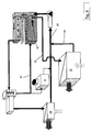
- the Figures 3 and 4 show a separate coolant circuit 16 ("split-cooling system") of an internal combustion engine 17, wherein a cylinder head water jacket 18 and an engine block water jacket 19 (FIG. FIG. 4 ) is provided.
- the separate coolant circuit 16 has a pump 21, a radiator 22, a thermostat 23 and a heater 24, wherein in the separate coolant circuit 16, a coolant circulates.
- the thermostat 23 is arranged to simultaneously control a flow of the coolant through the engine block water jacket 19 and through the radiator 22 when the coolant exceeds a predetermined temperature ( FIG. 4 ).
- the predetermined temperature should be 90 ° C in the illustrated embodiments, so that the thermostat is closed below a coolant temperature of 90 ° C ( FIG. 3 ) and opened above a coolant temperature of 90 ° C. is ( FIG. 4 ).
- the indicated coolant temperature is given by way of example only, and is not intended to be limiting.
- the thermostat 23 is disposed between the engine 17 and the heater 24.
- the heater 24 is connected via a connecting line 26 to the pump 21, which is connected via a connecting line 27 to the engine 17. Again FIG. 3 can be seen, the coolant flows from the pump 21, starting directly into the cylinder head water jacket 18 and is supplied from there via a connecting line 28 to the thermostat 23.
- the thermostat 23 is designed as a single-acting thermostat so that it is closed at a coolant temperature below the exemplified 90 ° C, which means that the coolant is fed through the thermostat 23 directly to the heater 24, which of course also a connecting line 29th is provided. It is easily conceivable that a warm-up phase of the internal combustion engine 17 can be significantly reduced by this arrangement, since the engine block is not initially cooled.
- the thermostat 23 opens to a connecting line 32, which is connected to the engine block water jacket 19 ( FIG. 4 ).
- the coolant flows like the FIG. 4 can be seen, by the thermostat 23 so both to the heater 24 and to the engine block water jacket 19.
- the coolant flows via a connecting line 33 to the radiator 22, wherein the coolant is cooled here similar to the heater 24.
- the radiator 22 is connected via a connecting line 34 with the connecting line 26 of the heater 24 to the pump 21, wherein the connecting line 34 opens into the connecting line 26.
- FIG. 4 Next is the FIG. 4 can be seen that the degassing device 31 with the connecting line 32 of the thermostat 23 to the engine block water jacket 19 and on the other hand with the connecting line 26 of the heater 24 is connected to the pump 21.
- the warm-up of the engine is considerably shortened, this effect using known components surprisingly by a different arrangement of the components, in particular the thermostat 23, which is advantageously designed as a low-cost, single-acting thermostat is achieved.
Landscapes
- Engineering & Computer Science (AREA)
- Chemical & Material Sciences (AREA)
- Combustion & Propulsion (AREA)
- Mechanical Engineering (AREA)
- General Engineering & Computer Science (AREA)
- Cylinder Crankcases Of Internal Combustion Engines (AREA)
Claims (3)
- Circuit de réfrigérant séparé d'un moteur à combustion interne (17), une chemise d'eau de culasse (18) et une chemise d'eau du bloc moteur (19) étant prévues, le circuit de réfrigérant séparé (16) présentant une pompe (21), un radiateur (22), un thermostat unique (23) et un chauffage (24), et un réfrigérant circulant dans le circuit de réfrigérant séparé (16), le thermostat (23) étant disposé de telle sorte qu'il commande simultanément un écoulement du réfrigérant à travers la chemise d'eau du bloc moteur (19) et à travers le radiateur (22), quand le réfrigérant dépasse une température prédéfinie,
caractérisé en ce que
le thermostat (23), vu dans la direction d'écoulement du réfrigérant, est disposé entre le moteur à combustion interne (17) et le chauffage (24), qui est connecté par le biais d'une conduite de connexion (26) à la pompe (21), le radiateur (22) étant connecté grâce à la conduite de connexion (26) du chauffage (24) à la pompe (21), et le réfrigérant étant acheminé en s'écoulant hors de la chemise d'eau de la culasse (18) à travers le thermostat (23) uniquement au chauffage (24), quand le réfrigérant présente une valeur de température en dessous de la température prédéfinie, et le réfrigérant s'écoulant à travers le thermostat (23) à la fois vers le chauffage (24) et vers la chemise d'eau du bloc moteur (19), hors de laquelle le réfrigérant s'écoule par le biais d'une conduite de connexion (33) vers le radiateur (22) quand le réfrigérant dépasse la température prédéfinie. - Circuit de réfrigérant séparé selon la revendication 1,
caractérisé en ce que
le thermostat (23) est connecté par le biais d'une conduite de connexion (32) à la chemise d'eau du bloc moteur (19). - Circuit de réfrigérant séparé selon la revendication 1 ou 2,
caractérisé en ce que
le thermostat (23) est réalisé sous forme de thermostat à fonction simple.
Priority Applications (3)
| Application Number | Priority Date | Filing Date | Title |
|---|---|---|---|
| DE502006009008T DE502006009008D1 (de) | 2006-09-13 | 2006-09-13 | Kühlmittelkreislauf |
| EP06120586A EP1900919B1 (fr) | 2006-09-13 | 2006-09-13 | Circuit de refroidissement |
| US11/853,067 US20080060592A1 (en) | 2006-09-13 | 2007-09-11 | Split Cooling System for an Internal Combustion Engine |
Applications Claiming Priority (1)
| Application Number | Priority Date | Filing Date | Title |
|---|---|---|---|
| EP06120586A EP1900919B1 (fr) | 2006-09-13 | 2006-09-13 | Circuit de refroidissement |
Publications (2)
| Publication Number | Publication Date |
|---|---|
| EP1900919A1 EP1900919A1 (fr) | 2008-03-19 |
| EP1900919B1 true EP1900919B1 (fr) | 2011-03-02 |
Family
ID=37110349
Family Applications (1)
| Application Number | Title | Priority Date | Filing Date |
|---|---|---|---|
| EP06120586A Not-in-force EP1900919B1 (fr) | 2006-09-13 | 2006-09-13 | Circuit de refroidissement |
Country Status (3)
| Country | Link |
|---|---|
| US (1) | US20080060592A1 (fr) |
| EP (1) | EP1900919B1 (fr) |
| DE (1) | DE502006009008D1 (fr) |
Cited By (5)
| Publication number | Priority date | Publication date | Assignee | Title |
|---|---|---|---|---|
| EP2562379A1 (fr) | 2011-08-23 | 2013-02-27 | Ford Global Technologies, LLC | Circuit d'agent réfrigérant |
| EP2562378A1 (fr) | 2011-08-23 | 2013-02-27 | Ford Global Technologies, LLC | Stratégie de fonctionnement d'un circuit d'agent réfrigérant séparé |
| US8739745B2 (en) | 2011-08-23 | 2014-06-03 | Ford Global Technologies, Llc | Cooling system and method |
| DE102014004009A1 (de) | 2014-03-20 | 2015-12-03 | Daimler Ag | Kühlmittelkreislauf zum Kühlen einer Verbrennungskraftmaschine, insbesondere für einen Kraftwagen, sowie Verfahren zum Betreiben eines solchen Kühlmittelkreislaufs |
| CN112065565A (zh) * | 2020-09-15 | 2020-12-11 | 奇瑞汽车股份有限公司 | 节温器总成、冷却系统、发动机和汽车 |
Families Citing this family (15)
| Publication number | Priority date | Publication date | Assignee | Title |
|---|---|---|---|---|
| US9849753B2 (en) * | 2008-05-16 | 2017-12-26 | GM Global Technology Operations LLC | Heating system for an automotive vehicle |
| DE102009001129B4 (de) * | 2009-02-25 | 2014-07-10 | Ford Global Technologies, Llc | Kühlstrategie für Verbrennungsmotoren |
| DE102009054814B4 (de) * | 2009-12-17 | 2013-11-28 | Ford Global Technologies, Llc | Verfahren zur Optimierung eines Thermomanagements in einem Kraftfahrzeug |
| DE102010002082B4 (de) | 2010-02-18 | 2013-09-19 | Ford Global Technologies, Llc | Separat gekühlter Abgassammler zur Aufrechterhaltung einer No-Flow Strategie des Zylinderblockkühlmittelmantels |
| EP2392794B1 (fr) | 2010-06-07 | 2019-02-27 | Ford Global Technologies, LLC | Turbosoufflante refroidie séparément pour le maintien d'une stratégie sans écoulement d'une enveloppe de réfrigérant à bloc cylindre |
| US8991339B2 (en) | 2012-03-30 | 2015-03-31 | Ford Global Technologies, Llc | Multi-zone vehicle radiators |
| AT513175B1 (de) * | 2012-07-26 | 2014-10-15 | Avl List Gmbh | Flüssigkühlsystem für eine Brennkraftmaschine eines Fahrzeuges |
| US9758171B2 (en) * | 2015-06-15 | 2017-09-12 | GM Global Technology Operations LLC | Method and apparatus for controlling a multi-mode powertrain system including an engine having stop/start capability |
| CN105673179B (zh) * | 2016-03-22 | 2018-04-20 | 浙江大学 | 一种基于分体冷却及反向冷却的发动机智能冷却系统试验台及试验方法 |
| JP6897347B2 (ja) * | 2017-06-08 | 2021-06-30 | スズキ株式会社 | エンジンの冷却用オイル通路構造 |
| US10538214B2 (en) * | 2017-11-15 | 2020-01-21 | Denso International America, Inc. | Controlled in-tank flow guide for heat exchanger |
| CN108049956B (zh) * | 2017-12-08 | 2024-01-23 | 重庆小康工业集团股份有限公司 | 发动机冷却系统 |
| DE102018218871A1 (de) | 2018-11-06 | 2020-05-07 | Ford Global Technologies, Llc | Anordnung und Verfahren zur Verringerung der Kondensatbildung in einem Zuluftstrang eines Verbrennungsmotors sowie Kraftfahrzeug |
| CN111963294B (zh) * | 2020-07-23 | 2024-05-10 | 广西玉柴机器股份有限公司 | 一种高效混动发动机冷却系统 |
| CN115839272B (zh) * | 2022-12-07 | 2025-06-27 | 河南坤宇无人机科技有限公司 | 一种航空重油活塞发动机系统 |
Citations (1)
| Publication number | Priority date | Publication date | Assignee | Title |
|---|---|---|---|---|
| JPH08218873A (ja) * | 1995-02-09 | 1996-08-27 | Toyota Motor Corp | 内燃機関の冷却装置 |
Family Cites Families (7)
| Publication number | Priority date | Publication date | Assignee | Title |
|---|---|---|---|---|
| IT1187952B (it) * | 1986-02-20 | 1987-12-23 | Fiat Auto Spa | Circuito di raffreddamento per motori a combustione interna |
| US5337704A (en) * | 1993-09-29 | 1994-08-16 | Chrysler Corporation | Engine cooling system with thermostat coolant flow control between head and block |
| US5385123A (en) * | 1993-10-08 | 1995-01-31 | Evans; John W. | Segregated cooling chambers for aqueous reverse-flow engine cooling systems |
| FR2750164B1 (fr) * | 1996-06-24 | 1998-09-11 | Peugeot | Dispositif de refroidissement d'un moteur a combustion interne |
| JP2003120291A (ja) * | 2001-10-10 | 2003-04-23 | Honda Motor Co Ltd | エンジンの冷却構造 |
| DE10219481A1 (de) * | 2002-04-30 | 2003-11-20 | Audi Ag | Verbrennungsmotor mit einem Zylinderkurbelgehäuse, mit einem Zylinderkopf und miteinem Kühlwasserkreislauf und Verfahren zum getrennten Kühlen des Zylinderkurbelgehäuses und des Zylinderkopfs, mit einem Kühlwasserkreislauf und einer gemeinsamen Kühlwasserpumpe |
| FR2860833B1 (fr) * | 2003-10-08 | 2007-06-01 | Peugeot Citroen Automobiles Sa | Circuit de refroidissement d'un moteur a combustion interne constitue d'au moins trois passages de refroidissement |
-
2006
- 2006-09-13 EP EP06120586A patent/EP1900919B1/fr not_active Not-in-force
- 2006-09-13 DE DE502006009008T patent/DE502006009008D1/de active Active
-
2007
- 2007-09-11 US US11/853,067 patent/US20080060592A1/en not_active Abandoned
Patent Citations (1)
| Publication number | Priority date | Publication date | Assignee | Title |
|---|---|---|---|---|
| JPH08218873A (ja) * | 1995-02-09 | 1996-08-27 | Toyota Motor Corp | 内燃機関の冷却装置 |
Cited By (7)
| Publication number | Priority date | Publication date | Assignee | Title |
|---|---|---|---|---|
| EP2562379A1 (fr) | 2011-08-23 | 2013-02-27 | Ford Global Technologies, LLC | Circuit d'agent réfrigérant |
| EP2562378A1 (fr) | 2011-08-23 | 2013-02-27 | Ford Global Technologies, LLC | Stratégie de fonctionnement d'un circuit d'agent réfrigérant séparé |
| US8739745B2 (en) | 2011-08-23 | 2014-06-03 | Ford Global Technologies, Llc | Cooling system and method |
| DE102014004009A1 (de) | 2014-03-20 | 2015-12-03 | Daimler Ag | Kühlmittelkreislauf zum Kühlen einer Verbrennungskraftmaschine, insbesondere für einen Kraftwagen, sowie Verfahren zum Betreiben eines solchen Kühlmittelkreislaufs |
| DE102014004009B4 (de) * | 2014-03-20 | 2025-12-31 | Mercedes-Benz Group AG | Kühlmittelkreislauf zum Kühlen einer Verbrennungskraftmaschine, insbesondere für einen Kraftwagen, sowie Verfahren zum Betreiben eines solchen Kühlmittelkreislaufs |
| CN112065565A (zh) * | 2020-09-15 | 2020-12-11 | 奇瑞汽车股份有限公司 | 节温器总成、冷却系统、发动机和汽车 |
| CN112065565B (zh) * | 2020-09-15 | 2021-11-30 | 奇瑞汽车股份有限公司 | 节温器总成、冷却系统、发动机和汽车 |
Also Published As
| Publication number | Publication date |
|---|---|
| EP1900919A1 (fr) | 2008-03-19 |
| US20080060592A1 (en) | 2008-03-13 |
| DE502006009008D1 (de) | 2011-04-14 |
Similar Documents
| Publication | Publication Date | Title |
|---|---|---|
| EP1900919B1 (fr) | Circuit de refroidissement | |
| EP2562379B1 (fr) | Circuit d'agent réfrigérant | |
| EP1947308B1 (fr) | Système de refroidissement de moteur intégré | |
| DE102010002082B4 (de) | Separat gekühlter Abgassammler zur Aufrechterhaltung einer No-Flow Strategie des Zylinderblockkühlmittelmantels | |
| DE102012200005B4 (de) | Verfahren zum Betreiben eines Kühlmittelkreislaufs | |
| EP2392794B1 (fr) | Turbosoufflante refroidie séparément pour le maintien d'une stratégie sans écoulement d'une enveloppe de réfrigérant à bloc cylindre | |
| DE102008035955B4 (de) | Kühlstrategie | |
| DE102014201717A1 (de) | Brennkraftmaschine mit flüssigkeitsgekühltem Zylinderkopf und Zylinderblock und Verfahren zur Steuerung der Kühlung einer derartigen Brennkraftmaschine | |
| DE102013214838A1 (de) | Brennkraftmaschine mit flüssigkeitsgekühltem Zylinderkopf und flüssigkeitsgekühltem Zylinderblock und Verfahren zum Betreiben einer derartigen Brennkraftmaschine | |
| DE102014215074A1 (de) | Temperieranordnung für Getriebeöl eines Kraftfahrzeugs sowie Verfahren zum Temperieren von Getriebeöl eines Kraftfahrzeugs | |
| DE102015201238B3 (de) | Verfahren zum Betrieb einer Brennkraftmaschine mit Split-Kühlsystem und Zylinderabschaltung | |
| DE102015201246A1 (de) | Regelmittel zur Steuerung der Kühlmittelströme eines Split-Kühlsystems | |
| DE112015000115B4 (de) | Abgasrückführungsventil, System zum Auftauen von Abgasrückführungsventil und Motor | |
| DE102010001752A1 (de) | Kühlsystem | |
| EP2562378B1 (fr) | Stratégie de fonctionnement d'un circuit d'agent réfrigérant séparé | |
| DE102015201242B4 (de) | Regelmittel zur Steuerung der Kühlmittelströme eines Split-Kühlsystems | |
| DE102015201240B4 (de) | Split-Kühlsystem sowie Brennkraftmaschine mit einem Split-Kühlsystem und entsprechend ausgestattetes Fahrzeug | |
| DE102017221915A1 (de) | Getrennte Kühleinrichtung und ein getrenntes Kühlsystem für ein Fahrzeug | |
| DE102013204056B4 (de) | Steuerung einer Kühlvorrichtung für einen Verbrennungsmotor eines Kraftfahrzeugs in Abhängigkeit von Betriebs- und Umgebungsbedingungen des Verbrennungsmotors | |
| WO2017012875A1 (fr) | Moteur à combustion interne muni d'un système de refroidissement en plusieurs parties | |
| EP2241734A1 (fr) | Culasse comprenant deux turbines en parallèle et procédé de gestion du fonctionnement d'un moteur à combustion interne comprenant une telle culasse | |
| DE202015100582U1 (de) | Regelmittel zur Steuerung der Kühlmittelströme eines Split Kühlsystems | |
| DE102012019091A1 (de) | Kurbelgehäuse für eine Verbrennungskraftmaschine sowie Verbrennungskraftmaschine mit einem solchen Kurbelgehäuse | |
| DE3517567A1 (de) | Antriebsanlage fuer geraete und fahrzeuge, insbesondere kraftfahrzeuge | |
| DE102010036581A1 (de) | Flüssigkeitsgekühlte Brennkraftmaschine mit kühlmittelbetriebener Heizung und Verfahren zum Betreiben einer derartigen Brennkraftmaschine |
Legal Events
| Date | Code | Title | Description |
|---|---|---|---|
| PUAI | Public reference made under article 153(3) epc to a published international application that has entered the european phase |
Free format text: ORIGINAL CODE: 0009012 |
|
| AK | Designated contracting states |
Kind code of ref document: A1 Designated state(s): AT BE BG CH CY CZ DE DK EE ES FI FR GB GR HU IE IS IT LI LT LU LV MC NL PL PT RO SE SI SK TR |
|
| AX | Request for extension of the european patent |
Extension state: AL BA HR MK YU |
|
| 17P | Request for examination filed |
Effective date: 20080919 |
|
| AKX | Designation fees paid |
Designated state(s): DE FR GB |
|
| 17Q | First examination report despatched |
Effective date: 20100319 |
|
| GRAP | Despatch of communication of intention to grant a patent |
Free format text: ORIGINAL CODE: EPIDOSNIGR1 |
|
| GRAS | Grant fee paid |
Free format text: ORIGINAL CODE: EPIDOSNIGR3 |
|
| GRAA | (expected) grant |
Free format text: ORIGINAL CODE: 0009210 |
|
| AK | Designated contracting states |
Kind code of ref document: B1 Designated state(s): DE FR GB |
|
| REG | Reference to a national code |
Ref country code: GB Ref legal event code: FG4D Free format text: NOT ENGLISH |
|
| REF | Corresponds to: |
Ref document number: 502006009008 Country of ref document: DE Date of ref document: 20110414 Kind code of ref document: P |
|
| REG | Reference to a national code |
Ref country code: DE Ref legal event code: R096 Ref document number: 502006009008 Country of ref document: DE Effective date: 20110414 |
|
| PLBE | No opposition filed within time limit |
Free format text: ORIGINAL CODE: 0009261 |
|
| STAA | Information on the status of an ep patent application or granted ep patent |
Free format text: STATUS: NO OPPOSITION FILED WITHIN TIME LIMIT |
|
| 26N | No opposition filed |
Effective date: 20111205 |
|
| REG | Reference to a national code |
Ref country code: DE Ref legal event code: R097 Ref document number: 502006009008 Country of ref document: DE Effective date: 20111205 |
|
| REG | Reference to a national code |
Ref country code: FR Ref legal event code: PLFP Year of fee payment: 11 |
|
| REG | Reference to a national code |
Ref country code: FR Ref legal event code: PLFP Year of fee payment: 12 |
|
| REG | Reference to a national code |
Ref country code: FR Ref legal event code: PLFP Year of fee payment: 13 |
|
| PGFP | Annual fee paid to national office [announced via postgrant information from national office to epo] |
Ref country code: FR Payment date: 20190819 Year of fee payment: 14 |
|
| PGFP | Annual fee paid to national office [announced via postgrant information from national office to epo] |
Ref country code: GB Payment date: 20190827 Year of fee payment: 14 |
|
| GBPC | Gb: european patent ceased through non-payment of renewal fee |
Effective date: 20200913 |
|
| PG25 | Lapsed in a contracting state [announced via postgrant information from national office to epo] |
Ref country code: FR Free format text: LAPSE BECAUSE OF NON-PAYMENT OF DUE FEES Effective date: 20200930 |
|
| PG25 | Lapsed in a contracting state [announced via postgrant information from national office to epo] |
Ref country code: GB Free format text: LAPSE BECAUSE OF NON-PAYMENT OF DUE FEES Effective date: 20200913 |
|
| PGFP | Annual fee paid to national office [announced via postgrant information from national office to epo] |
Ref country code: DE Payment date: 20220615 Year of fee payment: 17 |
|
| P01 | Opt-out of the competence of the unified patent court (upc) registered |
Effective date: 20230620 |
|
| REG | Reference to a national code |
Ref country code: DE Ref legal event code: R119 Ref document number: 502006009008 Country of ref document: DE |
|
| PG25 | Lapsed in a contracting state [announced via postgrant information from national office to epo] |
Ref country code: DE Free format text: LAPSE BECAUSE OF NON-PAYMENT OF DUE FEES Effective date: 20240403 |