EP1900925A2 - Dämpfer für Stösse - Google Patents
Dämpfer für Stösse Download PDFInfo
- Publication number
- EP1900925A2 EP1900925A2 EP07075780A EP07075780A EP1900925A2 EP 1900925 A2 EP1900925 A2 EP 1900925A2 EP 07075780 A EP07075780 A EP 07075780A EP 07075780 A EP07075780 A EP 07075780A EP 1900925 A2 EP1900925 A2 EP 1900925A2
- Authority
- EP
- European Patent Office
- Prior art keywords
- gear
- stop
- damper
- housing
- spring
- Prior art date
- Legal status (The legal status is an assumption and is not a legal conclusion. Google has not performed a legal analysis and makes no representation as to the accuracy of the status listed.)
- Withdrawn
Links
Images

Classifications
-
- F—MECHANICAL ENGINEERING; LIGHTING; HEATING; WEAPONS; BLASTING
- F02—COMBUSTION ENGINES; HOT-GAS OR COMBUSTION-PRODUCT ENGINE PLANTS
- F02D—CONTROLLING COMBUSTION ENGINES
- F02D9/00—Controlling engines by throttling air or fuel-and-air induction conduits or exhaust conduits
- F02D9/08—Throttle valves specially adapted therefor; Arrangements of such valves in conduits
- F02D9/10—Throttle valves specially adapted therefor; Arrangements of such valves in conduits having pivotally-mounted flaps
- F02D9/107—Manufacturing or mounting details
-
- F—MECHANICAL ENGINEERING; LIGHTING; HEATING; WEAPONS; BLASTING
- F16—ENGINEERING ELEMENTS AND UNITS; GENERAL MEASURES FOR PRODUCING AND MAINTAINING EFFECTIVE FUNCTIONING OF MACHINES OR INSTALLATIONS; THERMAL INSULATION IN GENERAL
- F16H—GEARING
- F16H19/00—Gearings comprising essentially only toothed gears or friction members and not capable of conveying indefinitely-continuing rotary motion
- F16H19/001—Gearings comprising essentially only toothed gears or friction members and not capable of conveying indefinitely-continuing rotary motion for conveying reciprocating or limited rotary motion
-
- F—MECHANICAL ENGINEERING; LIGHTING; HEATING; WEAPONS; BLASTING
- F16—ENGINEERING ELEMENTS AND UNITS; GENERAL MEASURES FOR PRODUCING AND MAINTAINING EFFECTIVE FUNCTIONING OF MACHINES OR INSTALLATIONS; THERMAL INSULATION IN GENERAL
- F16H—GEARING
- F16H19/00—Gearings comprising essentially only toothed gears or friction members and not capable of conveying indefinitely-continuing rotary motion
- F16H19/001—Gearings comprising essentially only toothed gears or friction members and not capable of conveying indefinitely-continuing rotary motion for conveying reciprocating or limited rotary motion
- F16H2019/008—Facilitating the engagement or stopping of gear sections
Definitions
- the present invention relates to gear control in a mechanical or electromechanical assembly such as a controller or actuator, for example.
- gear driven controllers and actuators include a gear or gear trains as part of their control mechanism design.
- gear driven controllers and actuators include electronic throttle controls (ETCs) and actuators for controlling the opening and closing of a valve in a vehicle intake manifold.
- ETCs electronic throttle controls
- these components are subject to frequent and abrupt stopping movements when reaching their stopping points which subject the gears and surrounding components to high stresses that can result in a breakdown of the gear teeth and failure of the part. While various attempts have been made to dampen the abrupt stopping movement of the gear, these attempts usually involve the addition of separately mounted components which undesirably add to the size and cost of the assembly.
- the present invention provides a method and apparatus for reducing destructive forces on a gear caused by abrupt stopping of the gear by reducing or damping the rotational velocity and angular acceleration of a gear as the gear reaches its stopping point.
- a first gear is mounted in a gear housing and is connected to a shaft for controlling the movement of a component such as a throttle or valve blade, for example.
- the first gear may be mounted in meshing engagement with one or more additional gears as required by the particular controller or actuator design being employed.
- a rotational speed damper is mounted to one of the gear housing and the first gear, and a stop is mounted to the other of the housing or first gear. The stop and the damper are respectively positioned such that they come into contact with each other as the first gear approaches a first stopping point.
- the rotational speed damper is operable to dampen the speed of said first gear by gradually decreasing the rotational velocity and angular acceleration of the first gear over a time period beginning at the time the damper contacts the stop and ending at the time the first gear reaches its first stopping point.
- the damper may comprise one or more resilient cantilevers and the cantilevers may be of the same or different lengths.
- the cantilevers may be spaced from each other and may further include a rib interconnecting the cantilevers.
- the cantilevers may furthermore be formed of a first material and a spacer element may be formed of a second material and positioned in the space between the cantilevers.
- the second material may be less stiff or more stiff than the first material.
- the cantilevers may shorten in length in a direction away or toward from the stop.
- the damper may be a leaf spring or spring clip having first and second ends with one of the ends anchored to the gear housing or gear, and the other end left unanchored and free such that the spring flexes upon a force being applied adjacent the free end thereof.
- a second stop may be positioned in spaced, adjacent relationship to the spring free end on the side of the spring opposite the first stop, the second stop defining the flexing limit of the spring upon impact with the first stop.
- the first stop may be positioned on the gear and said second stop may be positioned on the housing.
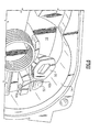
- FIG. 1 one embodiment of the invention incorporated into an electronic throttle control (ETC) 10. It is understood, however, that the invention is applicable to any type of apparatus having one or more gears where dampening of the gear stopping movement is desired.
- ETC electronic throttle control
- first gear 12 is mounted in a gear housing 14.
- the first gear may be mounted in meshing engagement with one or more additional gears as required by the particular controller design being employed.
- first gear 12 may be placed in meshing engagement with a second gear 16 which is coaxially mounted to a third gear 18 mounted in meshing engagement with a fourth gear 20.
- a shaft extends from the center 12a of the first gear 12 for attaching to and controlling the movement of a component (not shown) such as a throttle valve blade, for example.
- a prior art gear stop 11 having a rigid back fin 11 a is mounted on gear 12.
- a stop 13 is mounted to the gear housing (not shown in Fig. 2) to stop the turning of gear 12 at the appropriate location. Since back fin 11a is rigid, it does not absorb an appreciable amount of the stopping force as gear stop 11 strikes cylindrical stop 13. This may result in the gear teeth absorbing the force resulting in damaged gear teeth.
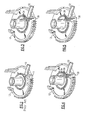
- a rotational speed damper 30 is mounted to the first gear 12, and a stop 32 is mounted to the gear housing 14 (gear housing 14 not shown in Figs. 3-5).
- the damper 30 may be mounted to the gear housing 14 and the stop 32 may be mounted to the gear 12.
- the stop 32 and the damper 30 are respectively positioned such that they come into contact with each other as the first gear 30 approaches a first stopping point.
- the rotational speed damper 30 is operable to dampen the speed of the first gear 12 by gradually decreasing the rotational velocity and angular acceleration of the first gear 12 over a time period beginning at the time the damper 30 contacts the stop 32 and ending at the time the first gear reaches its first stopping point.
- the damper 30 may comprise one or more resilient cantilevers 34 and the cantilevers may be of the same or different lengths as shown.
- the cantilevers 34 may contact or be spaced from each other as shown.
- a connecting rib 36 may interconnect the spaced cantilevers 34 as seen in Fig. 5.
- the cantilevers 34 may formed of a first resilient material such as plastic, for example.
- a spacer element 38 may be provided and formed of a second material and positioned in the space between the cantilevers 34 as shown in the embodiment of Fig. 4.
- the second material may be less stiff or more stiff than the first material to obtain the desired dampening effect.
- the cantilevers 34 may shorten in length in a direction away or toward the stop 32. In the embodiments of Figs. 3-5, cantilevers 34 shorten in a direction away from stop 32.
- the damper 40 may be a leaf spring or clip including first and second ends 40a and 40b, respectively, with one of the ends 40a anchored to the housing or gear, and the other end 40b left unanchored and free such that the spring 40 flexes to absorb a force being applied adjacent the free end 40b thereof by first stop 50.
- a second stop 52 may be positioned in spaced, adjacent relationship to the spring free (second) end 40b on the side of the spring 40 opposite the first stop 50, the second stop 52 defining the flexing limit of the spring 40 upon the first stop 50 pressing spring free end 40b against second stop 52.
- the first stop 50 may be positioned on the gear 12 and said second stop 52 may be positioned on the housing 14.
Landscapes
- Engineering & Computer Science (AREA)
- General Engineering & Computer Science (AREA)
- Mechanical Engineering (AREA)
- Manufacturing & Machinery (AREA)
- Chemical & Material Sciences (AREA)
- Combustion & Propulsion (AREA)
- Control Of Throttle Valves Provided In The Intake System Or In The Exhaust System (AREA)
- Mechanical Operated Clutches (AREA)
- Transmission Devices (AREA)
Applications Claiming Priority (1)
| Application Number | Priority Date | Filing Date | Title |
|---|---|---|---|
| US11/522,870 US20080067029A1 (en) | 2006-09-18 | 2006-09-18 | Impact damper mechanism |
Publications (2)
| Publication Number | Publication Date |
|---|---|
| EP1900925A2 true EP1900925A2 (de) | 2008-03-19 |
| EP1900925A3 EP1900925A3 (de) | 2008-05-14 |
Family
ID=38823647
Family Applications (1)
| Application Number | Title | Priority Date | Filing Date |
|---|---|---|---|
| EP07075780A Withdrawn EP1900925A3 (de) | 2006-09-18 | 2007-09-10 | Dämpfer für Stösse |
Country Status (2)
| Country | Link |
|---|---|
| US (1) | US20080067029A1 (de) |
| EP (1) | EP1900925A3 (de) |
Families Citing this family (3)
| Publication number | Priority date | Publication date | Assignee | Title |
|---|---|---|---|---|
| EP2552291B1 (de) * | 2010-04-01 | 2018-03-28 | Columbia Insurance Company | Antriebssystem |
| JP6218196B2 (ja) * | 2016-03-23 | 2017-10-25 | 株式会社東海理化電機製作所 | 歯車駆動装置 |
| JP2023161736A (ja) * | 2022-04-26 | 2023-11-08 | 株式会社ミクニ | エンジンのスロットル装置 |
Family Cites Families (5)
| Publication number | Priority date | Publication date | Assignee | Title |
|---|---|---|---|---|
| AT402391B (de) * | 1994-12-30 | 1997-04-25 | Haas Beteiligungsgesellschaft | Kunststoffeder |
| DE19928632A1 (de) * | 1999-06-23 | 2000-12-28 | Mannesmann Vdo Ag | Lastverstellvorrichtung |
| EP1098078A3 (de) * | 1999-11-08 | 2002-07-03 | Siemens Canada Limited | Elektronisch gesteuerte Drosselklappe mit Notfahreinrichtung |
| DE10126471B4 (de) * | 2001-05-31 | 2011-06-22 | Continental Automotive GmbH, 30165 | Antriebseinrichtung |
| JP4366324B2 (ja) * | 2005-03-17 | 2009-11-18 | 三菱電機株式会社 | 内燃機関用吸気量制御装置 |
-
2006
- 2006-09-18 US US11/522,870 patent/US20080067029A1/en not_active Abandoned
-
2007
- 2007-09-10 EP EP07075780A patent/EP1900925A3/de not_active Withdrawn
Also Published As
| Publication number | Publication date |
|---|---|
| EP1900925A3 (de) | 2008-05-14 |
| US20080067029A1 (en) | 2008-03-20 |
Similar Documents
| Publication | Publication Date | Title |
|---|---|---|
| CN101725415B (zh) | 具有渐进双孔电子节气门体的发动机 | |
| EP2356523B1 (de) | Hvac-aktuator mit ausgangsdrehmomentkompensation | |
| CN103375277B (zh) | 具有电子定位线圈的节流回复弹簧 | |
| EP1091149B1 (de) | Dämpfer für Schaltgestänge | |
| WO2003083957A3 (en) | Piezoelectric actuator for moving folded-back arms | |
| EP1900925A2 (de) | Dämpfer für Stösse | |
| JP2009068644A (ja) | スプリング装置およびアクセルペダル装置 | |
| CN1113283C (zh) | 油门踏板 | |
| JP2007107468A (ja) | 電子制御式スロットル弁装置 | |
| JP4220504B2 (ja) | 吸気制御システム | |
| CN102392742A (zh) | 电子节气门体 | |
| CN1317806C (zh) | 电动机组装体及其电动阀 | |
| KR20010049617A (ko) | 부하 조절 장치 | |
| CN106931227A (zh) | 通过齿轮系统进行运动传递的传动装置和包括传动装置的致动系统 | |
| US7287504B2 (en) | Over-center actuator | |
| JP5183641B2 (ja) | 弁部材の線形の運動のための装置 | |
| JP4366324B2 (ja) | 内燃機関用吸気量制御装置 | |
| KR20130064082A (ko) | 내연기관의 배기 밸브를 제어하기 위한 장치 | |
| KR101611974B1 (ko) | 기어하우징과 토션스프링의 장착구조 | |
| JPH11173166A (ja) | 車両用歯車伝達機構と吸気量制御装置 | |
| EP3871916A1 (de) | Beschleunigervorrichtung eines fahrzeugs | |
| DE10328554A1 (de) | Pedal | |
| KR20020084210A (ko) | 전동 클러치 디스크 | |
| KR100750405B1 (ko) | 전자제어식 쓰로틀밸브장치 | |
| JP4317494B2 (ja) | 多連式スロットルボディのバルブシャフトリンク機構 |
Legal Events
| Date | Code | Title | Description |
|---|---|---|---|
| PUAI | Public reference made under article 153(3) epc to a published international application that has entered the european phase |
Free format text: ORIGINAL CODE: 0009012 |
|
| AK | Designated contracting states |
Kind code of ref document: A2 Designated state(s): AT BE BG CH CY CZ DE DK EE ES FI FR GB GR HU IE IS IT LI LT LU LV MC MT NL PL PT RO SE SI SK TR |
|
| AX | Request for extension of the european patent |
Extension state: AL BA HR MK YU |
|
| PUAL | Search report despatched |
Free format text: ORIGINAL CODE: 0009013 |
|
| AK | Designated contracting states |
Kind code of ref document: A3 Designated state(s): AT BE BG CH CY CZ DE DK EE ES FI FR GB GR HU IE IS IT LI LT LU LV MC MT NL PL PT RO SE SI SK TR |
|
| AX | Request for extension of the european patent |
Extension state: AL BA HR MK RS |
|
| 17P | Request for examination filed |
Effective date: 20081114 |
|
| 17Q | First examination report despatched |
Effective date: 20081215 |
|
| AKX | Designation fees paid |
Designated state(s): AT BE BG CH CY CZ DE DK EE ES FI FR GB GR HU IE IS IT LI LT LU LV MC MT NL PL PT RO SE SI SK TR |
|
| GRAP | Despatch of communication of intention to grant a patent |
Free format text: ORIGINAL CODE: EPIDOSNIGR1 |
|
| STAA | Information on the status of an ep patent application or granted ep patent |
Free format text: STATUS: THE APPLICATION IS DEEMED TO BE WITHDRAWN |
|
| 18D | Application deemed to be withdrawn |
Effective date: 20110104 |