EP1900933A2 - Soupape d'injection de carburant - Google Patents
Soupape d'injection de carburant Download PDFInfo
- Publication number
- EP1900933A2 EP1900933A2 EP07016402A EP07016402A EP1900933A2 EP 1900933 A2 EP1900933 A2 EP 1900933A2 EP 07016402 A EP07016402 A EP 07016402A EP 07016402 A EP07016402 A EP 07016402A EP 1900933 A2 EP1900933 A2 EP 1900933A2
- Authority
- EP
- European Patent Office
- Prior art keywords
- injection valve
- fuel injection
- roughness
- valve according
- housing
- Prior art date
- Legal status (The legal status is an assumption and is not a legal conclusion. Google has not performed a legal analysis and makes no representation as to the accuracy of the status listed.)
- Granted
Links
- 239000000446 fuel Substances 0.000 title claims abstract description 45
- 238000002347 injection Methods 0.000 title claims description 36
- 239000007924 injection Substances 0.000 title claims description 36
- 238000002485 combustion reaction Methods 0.000 claims description 10
- 239000000463 material Substances 0.000 claims description 10
- 238000005229 chemical vapour deposition Methods 0.000 claims description 5
- 238000000926 separation method Methods 0.000 claims description 5
- 238000012993 chemical processing Methods 0.000 claims description 3
- 238000005240 physical vapour deposition Methods 0.000 description 4
- 238000012545 processing Methods 0.000 description 4
- 239000004071 soot Substances 0.000 description 4
- 238000003754 machining Methods 0.000 description 3
- 238000004519 manufacturing process Methods 0.000 description 3
- 239000007921 spray Substances 0.000 description 3
- 238000000889 atomisation Methods 0.000 description 2
- 238000000151 deposition Methods 0.000 description 2
- 230000008021 deposition Effects 0.000 description 2
- 230000000694 effects Effects 0.000 description 2
- 239000000203 mixture Substances 0.000 description 2
- 230000003746 surface roughness Effects 0.000 description 2
- 244000188595 Brassica sinapistrum Species 0.000 description 1
- 235000004977 Brassica sinapistrum Nutrition 0.000 description 1
- 240000003517 Elaeocarpus dentatus Species 0.000 description 1
- 239000002253 acid Substances 0.000 description 1
- 230000003466 anti-cipated effect Effects 0.000 description 1
- 230000015572 biosynthetic process Effects 0.000 description 1
- 238000005422 blasting Methods 0.000 description 1
- 238000005553 drilling Methods 0.000 description 1
- 238000005530 etching Methods 0.000 description 1
- 238000000227 grinding Methods 0.000 description 1
- 239000007788 liquid Substances 0.000 description 1
- 238000000034 method Methods 0.000 description 1
- 150000004702 methyl esters Chemical class 0.000 description 1
- 239000002245 particle Substances 0.000 description 1
- 238000002360 preparation method Methods 0.000 description 1
- 230000002035 prolonged effect Effects 0.000 description 1
- 238000007789 sealing Methods 0.000 description 1
- 238000005507 spraying Methods 0.000 description 1
- 239000000126 substance Substances 0.000 description 1
Images
Classifications
-
- F—MECHANICAL ENGINEERING; LIGHTING; HEATING; WEAPONS; BLASTING
- F02—COMBUSTION ENGINES; HOT-GAS OR COMBUSTION-PRODUCT ENGINE PLANTS
- F02M—SUPPLYING COMBUSTION ENGINES IN GENERAL WITH COMBUSTIBLE MIXTURES OR CONSTITUENTS THEREOF
- F02M61/00—Fuel-injectors not provided for in groups F02M39/00 - F02M57/00 or F02M67/00
- F02M61/04—Fuel-injectors not provided for in groups F02M39/00 - F02M57/00 or F02M67/00 having valves, e.g. having a plurality of valves in series
- F02M61/08—Fuel-injectors not provided for in groups F02M39/00 - F02M57/00 or F02M67/00 having valves, e.g. having a plurality of valves in series the valves opening in direction of fuel flow
-
- F—MECHANICAL ENGINEERING; LIGHTING; HEATING; WEAPONS; BLASTING
- F02—COMBUSTION ENGINES; HOT-GAS OR COMBUSTION-PRODUCT ENGINE PLANTS
- F02M—SUPPLYING COMBUSTION ENGINES IN GENERAL WITH COMBUSTIBLE MIXTURES OR CONSTITUENTS THEREOF
- F02M61/00—Fuel-injectors not provided for in groups F02M39/00 - F02M57/00 or F02M67/00
- F02M61/16—Details not provided for in, or of interest apart from, the apparatus of groups F02M61/02 - F02M61/14
- F02M61/18—Injection nozzles, e.g. having valve seats; Details of valve member seated ends, not otherwise provided for
-
- F—MECHANICAL ENGINEERING; LIGHTING; HEATING; WEAPONS; BLASTING
- F02—COMBUSTION ENGINES; HOT-GAS OR COMBUSTION-PRODUCT ENGINE PLANTS
- F02M—SUPPLYING COMBUSTION ENGINES IN GENERAL WITH COMBUSTIBLE MIXTURES OR CONSTITUENTS THEREOF
- F02M2200/00—Details of fuel-injection apparatus, not otherwise provided for
- F02M2200/06—Fuel-injection apparatus having means for preventing coking, e.g. of fuel injector discharge orifices or valve needles
-
- F—MECHANICAL ENGINEERING; LIGHTING; HEATING; WEAPONS; BLASTING
- F02—COMBUSTION ENGINES; HOT-GAS OR COMBUSTION-PRODUCT ENGINE PLANTS
- F02M—SUPPLYING COMBUSTION ENGINES IN GENERAL WITH COMBUSTIBLE MIXTURES OR CONSTITUENTS THEREOF
- F02M2200/00—Details of fuel-injection apparatus, not otherwise provided for
- F02M2200/80—Fuel injection apparatus manufacture, repair or assembly
- F02M2200/8069—Fuel injection apparatus manufacture, repair or assembly involving removal of material from the fuel apparatus, e.g. by punching, hydro-erosion or mechanical operation
-
- F—MECHANICAL ENGINEERING; LIGHTING; HEATING; WEAPONS; BLASTING
- F02—COMBUSTION ENGINES; HOT-GAS OR COMBUSTION-PRODUCT ENGINE PLANTS
- F02M—SUPPLYING COMBUSTION ENGINES IN GENERAL WITH COMBUSTIBLE MIXTURES OR CONSTITUENTS THEREOF
- F02M2200/00—Details of fuel-injection apparatus, not otherwise provided for
- F02M2200/90—Selection of particular materials
- F02M2200/9038—Coatings
Definitions
- the invention relates to a fuel injection valve having the features of the preamble of patent claim 1.
- a cylinder head for an internal combustion engine with a combustion chamber provided in the spark plug is described. Furthermore, the cylinder head has an injection nozzle having a housing end face, which has a closure element which can be moved via an actuator and has a closure body. The housing end face of the injection nozzle forms with the closure body in the closed state a common, planar surface.
- the ignition safety is ensured at each operating point of the internal combustion engine and a change in the fuel jet geometry by combustion residues at the nozzle opening of the injection nozzle is anticipated.
- soot may deposit during prolonged operation of the internal combustion engine in the region of the tip of the injection nozzle, whereby the fuel jet pattern is changed.
- Object of the present invention is to show a measure that avoids a change in the atomization of the fuel, or the fuel spray pattern over time.
- the tip of the fuel injection valve receives a geometry from the production, as obtained by the fuel injection valve in the prior art only by deposits of soot particles at the top over the term.
- the fuel injection valve according to the invention has a geometry which corresponds to that of an aged fuel injection valve. The embodiment according to the invention thus does not change the atomization of the fuel or the fuel spray pattern and thus the mixture formation in the internal combustion engine over time.
- the roughness can be achieved by any geometric fatiguenausformmaschine according to claim 4.
- the roughness can be generated either by material removal or by material application.
- the roughness can be achieved by mechanical or chemical processing.
- PVD Physical Vapor Deposition
- CVD Chemical Vapor Deposition
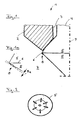
- FIG. 1 shows the tip of a fuel injection valve 1 configured according to the invention. Shown is a half section, wherein a housing 2 is cut and a closure element 4 with a housing-side closure body 5 is not shown cut. The cut surface of the housing 2 is hatched. Since the fuel injection valve 1 is rotationally symmetrical, only one side is shown along a longitudinal axis 9.
- the closure element 4 is arranged to be movable in a bore 3 in the housing 2 and can be actuated by an actuating element, not shown. With the closure body 5, the bore 3 can be opened and closed. For this purpose, the exit region of the bore has an unnumbered rotationally symmetrical sealing seat between the housing 2 and the closure element 5.
- the closure element 4 is lifted to open the bore 3, for spraying fuel in an environment 7 of the housing 2.
- this may be a piezo fuel injection valve.
- a fuel then flows through an annular gap between the closure element 4 and the bore 3 into the environment 7.
- the closure body 5 has a radially outer flow-off edge 6 for the fuel.
- the closure body 5 has a roughness 8 at least in the region of the flow separation edge 6 on the side facing the environment 7.
- This roughness 8 simulates the deposition of soot in this area for a newly produced fuel injection valve 1.
- a subsequent deposition of soot thus does not change the mixture-forming properties of the inventively designed fuel injection valve.
- the roughness 8 preferably has a surface roughness R t of between 0.5 and 200 ⁇ m.
- the housing 2 it is also possible for the housing 2 to have a roughness 8 in the region of the closure body 5, likewise on the side facing the surroundings 7.
- the roughness 8 can of Ridges and / or dents and / or raised areas may be formed. These grooves and / or dents and / or raised regions preferably have a width or a diameter of between 0.5 and 100 ⁇ m. Furthermore, the grooves and / or dents and / or raised areas are preferably spaced apart by a maximum of 1000 ⁇ m. Of course, the grooves and / or dents and / or raised areas may also intersect or intersect.
- the roughness 8 can be generated by material removal or by material application.
- the material removal can be achieved for example by mechanical or chemical processing.
- mechanical processing is meant, for example, grinding or blasting with a hard material.
- chemical material removal is meant, for example, the etching of the surface, for example with an acid.
- the roughness 8, for example, by a PVD (physical vapor deposition) or a CVD method (chemical vapor deposition) take place.
- FIG. 2 shows a closure body 5 in the direction of the longitudinal axis 9. Arrows symbolize a machining direction in the processing of the closure body 5 for the inventive design of the fuel injection valve 1.
- the machining process is carried out in the present embodiment largely perpendicular to the flow separation edge 6. In other processing variants, the machining can also be made obliquely to the flow separation edge 6.
- any liquid fuel such. As gasoline or diesel or RME (rapeseed methyl ester), etc. are injected.
- the fuel injection valve 1 according to the invention is preferably used in internal combustion engines with a high-pressure injection of the fuel directly into the combustion chamber. Of course, it can also be used in conjunction with a low-pressure injection.
Landscapes
- Engineering & Computer Science (AREA)
- Chemical & Material Sciences (AREA)
- Combustion & Propulsion (AREA)
- Mechanical Engineering (AREA)
- General Engineering & Computer Science (AREA)
- Fuel-Injection Apparatus (AREA)
Applications Claiming Priority (1)
| Application Number | Priority Date | Filing Date | Title |
|---|---|---|---|
| DE200610042444 DE102006042444A1 (de) | 2006-09-09 | 2006-09-09 | Kraftstoffeinspritzventil |
Publications (3)
| Publication Number | Publication Date |
|---|---|
| EP1900933A2 true EP1900933A2 (fr) | 2008-03-19 |
| EP1900933A3 EP1900933A3 (fr) | 2010-10-20 |
| EP1900933B1 EP1900933B1 (fr) | 2011-11-30 |
Family
ID=38739487
Family Applications (1)
| Application Number | Title | Priority Date | Filing Date |
|---|---|---|---|
| EP20070016402 Not-in-force EP1900933B1 (fr) | 2006-09-09 | 2007-08-22 | Soupape d'injection de carburant |
Country Status (2)
| Country | Link |
|---|---|
| EP (1) | EP1900933B1 (fr) |
| DE (1) | DE102006042444A1 (fr) |
Cited By (2)
| Publication number | Priority date | Publication date | Assignee | Title |
|---|---|---|---|---|
| WO2011029941A1 (fr) * | 2009-09-14 | 2011-03-17 | Continental Automotive Gmbh | Module buse pour soupape d'injection, et soupape d'injection correspondante |
| WO2012143178A1 (fr) * | 2011-04-21 | 2012-10-26 | Robert Bosch Gmbh | Composant, en particulier composant d'un système d'injection de carburant possédant une surface |
Family Cites Families (7)
| Publication number | Priority date | Publication date | Assignee | Title |
|---|---|---|---|---|
| US4408722A (en) * | 1981-05-29 | 1983-10-11 | General Motors Corporation | Fuel injection nozzle with grooved poppet valve |
| DE19726727A1 (de) * | 1997-06-24 | 1999-01-07 | Bosch Gmbh Robert | Brennstoffeinspritzventil oder Brennstoffeinspritzdüse |
| FR2772432B1 (fr) * | 1997-12-12 | 2000-02-18 | Magneti Marelli France | Injecteur d'essence a revetement ceramique anti-calamine, pour injection directe |
| DE10012969B4 (de) * | 2000-03-16 | 2008-06-19 | Daimler Ag | Einspritzdüse und ein Verfahren zur Bildung eines Kraftstoff-Luftgemischs |
| JP2002364492A (ja) * | 2001-05-31 | 2002-12-18 | Unisia Jecs Corp | 燃料噴射弁 |
| DE10344584A1 (de) * | 2003-09-25 | 2005-04-28 | Bosch Gmbh Robert | Brennstoffeinspritzventil |
| DE10350548A1 (de) * | 2003-10-29 | 2005-06-02 | Robert Bosch Gmbh | Brennstoffeinspritzventil |
-
2006
- 2006-09-09 DE DE200610042444 patent/DE102006042444A1/de not_active Withdrawn
-
2007
- 2007-08-22 EP EP20070016402 patent/EP1900933B1/fr not_active Not-in-force
Non-Patent Citations (1)
| Title |
|---|
| None |
Cited By (2)
| Publication number | Priority date | Publication date | Assignee | Title |
|---|---|---|---|---|
| WO2011029941A1 (fr) * | 2009-09-14 | 2011-03-17 | Continental Automotive Gmbh | Module buse pour soupape d'injection, et soupape d'injection correspondante |
| WO2012143178A1 (fr) * | 2011-04-21 | 2012-10-26 | Robert Bosch Gmbh | Composant, en particulier composant d'un système d'injection de carburant possédant une surface |
Also Published As
| Publication number | Publication date |
|---|---|
| EP1900933B1 (fr) | 2011-11-30 |
| DE102006042444A1 (de) | 2008-03-27 |
| EP1900933A3 (fr) | 2010-10-20 |
Similar Documents
| Publication | Publication Date | Title |
|---|---|---|
| EP2480783B1 (fr) | Soupape d'injection de carburant pour un moteur à combustion interne | |
| EP3951160B1 (fr) | Soupape d'injection de carburant et procédé d'injection de carburant pour un gros moteur diesel, ainsi que gros moteur diesel | |
| EP1900933B1 (fr) | Soupape d'injection de carburant | |
| DE102015015518B4 (de) | Kraftstoff/Luft-Einspritzsystem für Verbrennungsmotoren | |
| EP1908952A3 (fr) | Injecteur pour une installation à injection de carburant | |
| DE3122883A1 (de) | "kraftstoffeinspritzanlage fuer eine brennkraftmaschine" | |
| DE102004044820A1 (de) | Brennstoffeinspritzventil | |
| WO2007057268A1 (fr) | Regeneration d'un filtre a particules par post-injection a intervalles | |
| EP1766225B1 (fr) | Injecteur "common rail" | |
| DE3135133A1 (de) | Kraftstoffeinspritz-drosselventil | |
| DE102009044785A1 (de) | Steuerventil zum Reduzieren der Einspritzmengenvariation und mit diesem versehener Injektor | |
| DE102012018780A1 (de) | Kraftstoff-Einspritzsystem einer Brennkraftmaschine | |
| WO2009141175A1 (fr) | Soupape d'injection de carburant | |
| AT512423A1 (de) | Einspritzdüse zum einspritzen von medien in den brennraum einer brennkraftmaschine | |
| WO2008058799A1 (fr) | Injecteur de carburant | |
| WO2007110268A1 (fr) | Élément filtrant dans un injecteur de carburant | |
| DE102015207629A1 (de) | Einspritzventil für Flüssigkeiten und Verfahren | |
| EP1740822B1 (fr) | Injecteur common rail | |
| DE102010062808A1 (de) | Düsenkörper mit konischem Einspritzloch | |
| EP1668240B1 (fr) | Soupape d'injection de carburant | |
| EP1067284A1 (fr) | Soupape d'injection de combustible | |
| DE102006003040A1 (de) | Kraftstoffinjektor | |
| DE102004024528A1 (de) | Kraftstoffeinspritzsystem | |
| DE102009002480A1 (de) | Kraftstoffeinspritzvorrichtung | |
| DE102018204491A1 (de) | Kraftstoffinjektor |
Legal Events
| Date | Code | Title | Description |
|---|---|---|---|
| PUAI | Public reference made under article 153(3) epc to a published international application that has entered the european phase |
Free format text: ORIGINAL CODE: 0009012 |
|
| AK | Designated contracting states |
Kind code of ref document: A2 Designated state(s): AT BE BG CH CY CZ DE DK EE ES FI FR GB GR HU IE IS IT LI LT LU LV MC MT NL PL PT RO SE SI SK TR |
|
| AX | Request for extension of the european patent |
Extension state: AL BA HR MK YU |
|
| PUAL | Search report despatched |
Free format text: ORIGINAL CODE: 0009013 |
|
| AK | Designated contracting states |
Kind code of ref document: A3 Designated state(s): AT BE BG CH CY CZ DE DK EE ES FI FR GB GR HU IE IS IT LI LT LU LV MC MT NL PL PT RO SE SI SK TR |
|
| AX | Request for extension of the european patent |
Extension state: AL BA HR MK RS |
|
| 17P | Request for examination filed |
Effective date: 20101110 |
|
| 17Q | First examination report despatched |
Effective date: 20110415 |
|
| AKX | Designation fees paid |
Designated state(s): DE FR GB IT |
|
| GRAP | Despatch of communication of intention to grant a patent |
Free format text: ORIGINAL CODE: EPIDOSNIGR1 |
|
| RIC1 | Information provided on ipc code assigned before grant |
Ipc: F02M 61/08 20060101AFI20110614BHEP Ipc: F02M 61/18 20060101ALI20110614BHEP |
|
| GRAS | Grant fee paid |
Free format text: ORIGINAL CODE: EPIDOSNIGR3 |
|
| GRAA | (expected) grant |
Free format text: ORIGINAL CODE: 0009210 |
|
| AK | Designated contracting states |
Kind code of ref document: B1 Designated state(s): DE FR GB IT |
|
| REG | Reference to a national code |
Ref country code: GB Ref legal event code: FG4D Free format text: NOT ENGLISH |
|
| REG | Reference to a national code |
Ref country code: DE Ref legal event code: R096 Ref document number: 502007008743 Country of ref document: DE Effective date: 20120301 |
|
| PLBE | No opposition filed within time limit |
Free format text: ORIGINAL CODE: 0009261 |
|
| STAA | Information on the status of an ep patent application or granted ep patent |
Free format text: STATUS: NO OPPOSITION FILED WITHIN TIME LIMIT |
|
| 26N | No opposition filed |
Effective date: 20120831 |
|
| REG | Reference to a national code |
Ref country code: DE Ref legal event code: R097 Ref document number: 502007008743 Country of ref document: DE Effective date: 20120831 |
|
| REG | Reference to a national code |
Ref country code: FR Ref legal event code: PLFP Year of fee payment: 10 |
|
| REG | Reference to a national code |
Ref country code: FR Ref legal event code: PLFP Year of fee payment: 11 |
|
| REG | Reference to a national code |
Ref country code: FR Ref legal event code: PLFP Year of fee payment: 12 |
|
| PGFP | Annual fee paid to national office [announced via postgrant information from national office to epo] |
Ref country code: IT Payment date: 20190821 Year of fee payment: 13 Ref country code: FR Payment date: 20190822 Year of fee payment: 13 |
|
| PGFP | Annual fee paid to national office [announced via postgrant information from national office to epo] |
Ref country code: GB Payment date: 20190827 Year of fee payment: 13 |
|
| GBPC | Gb: european patent ceased through non-payment of renewal fee |
Effective date: 20200822 |
|
| PG25 | Lapsed in a contracting state [announced via postgrant information from national office to epo] |
Ref country code: IT Free format text: LAPSE BECAUSE OF NON-PAYMENT OF DUE FEES Effective date: 20200822 Ref country code: FR Free format text: LAPSE BECAUSE OF NON-PAYMENT OF DUE FEES Effective date: 20200831 |
|
| PG25 | Lapsed in a contracting state [announced via postgrant information from national office to epo] |
Ref country code: GB Free format text: LAPSE BECAUSE OF NON-PAYMENT OF DUE FEES Effective date: 20200822 |
|
| PGFP | Annual fee paid to national office [announced via postgrant information from national office to epo] |
Ref country code: DE Payment date: 20220621 Year of fee payment: 16 |
|
| P01 | Opt-out of the competence of the unified patent court (upc) registered |
Effective date: 20230503 |
|
| REG | Reference to a national code |
Ref country code: DE Ref legal event code: R119 Ref document number: 502007008743 Country of ref document: DE |
|
| PG25 | Lapsed in a contracting state [announced via postgrant information from national office to epo] |
Ref country code: DE Free format text: LAPSE BECAUSE OF NON-PAYMENT OF DUE FEES Effective date: 20240301 |