EP1900935B1 - Verfahren zur Bearbeitung eines Injektionslochs in einem Düsenelement, Vorrichtung dafür sowie mit diesem Verfahren hergestellte Brennstoffeinspritzdüse und -vorrichtung - Google Patents
Verfahren zur Bearbeitung eines Injektionslochs in einem Düsenelement, Vorrichtung dafür sowie mit diesem Verfahren hergestellte Brennstoffeinspritzdüse und -vorrichtung Download PDFInfo
- Publication number
- EP1900935B1 EP1900935B1 EP07115245.8A EP07115245A EP1900935B1 EP 1900935 B1 EP1900935 B1 EP 1900935B1 EP 07115245 A EP07115245 A EP 07115245A EP 1900935 B1 EP1900935 B1 EP 1900935B1
- Authority
- EP
- European Patent Office
- Prior art keywords
- nozzle body
- abrasive fluid
- injection holes
- insert tool
- injection
- Prior art date
- Legal status (The legal status is an assumption and is not a legal conclusion. Google has not performed a legal analysis and makes no representation as to the accuracy of the status listed.)
- Not-in-force
Links
Images




Classifications
-
- F—MECHANICAL ENGINEERING; LIGHTING; HEATING; WEAPONS; BLASTING
- F02—COMBUSTION ENGINES; HOT-GAS OR COMBUSTION-PRODUCT ENGINE PLANTS
- F02M—SUPPLYING COMBUSTION ENGINES IN GENERAL WITH COMBUSTIBLE MIXTURES OR CONSTITUENTS THEREOF
- F02M61/00—Fuel-injectors not provided for in groups F02M39/00 - F02M57/00 or F02M67/00
- F02M61/16—Details not provided for in, or of interest apart from, the apparatus of groups F02M61/02 - F02M61/14
- F02M61/18—Injection nozzles, e.g. having valve seats; Details of valve member seated ends, not otherwise provided for
- F02M61/1806—Injection nozzles, e.g. having valve seats; Details of valve member seated ends, not otherwise provided for characterised by the arrangement of discharge orifices, e.g. orientation or size
-
- F—MECHANICAL ENGINEERING; LIGHTING; HEATING; WEAPONS; BLASTING
- F02—COMBUSTION ENGINES; HOT-GAS OR COMBUSTION-PRODUCT ENGINE PLANTS
- F02M—SUPPLYING COMBUSTION ENGINES IN GENERAL WITH COMBUSTIBLE MIXTURES OR CONSTITUENTS THEREOF
- F02M61/00—Fuel-injectors not provided for in groups F02M39/00 - F02M57/00 or F02M67/00
- F02M61/16—Details not provided for in, or of interest apart from, the apparatus of groups F02M61/02 - F02M61/14
- F02M61/168—Assembling; Disassembling; Manufacturing; Adjusting
-
- F—MECHANICAL ENGINEERING; LIGHTING; HEATING; WEAPONS; BLASTING
- F02—COMBUSTION ENGINES; HOT-GAS OR COMBUSTION-PRODUCT ENGINE PLANTS
- F02M—SUPPLYING COMBUSTION ENGINES IN GENERAL WITH COMBUSTIBLE MIXTURES OR CONSTITUENTS THEREOF
- F02M61/00—Fuel-injectors not provided for in groups F02M39/00 - F02M57/00 or F02M67/00
- F02M61/16—Details not provided for in, or of interest apart from, the apparatus of groups F02M61/02 - F02M61/14
- F02M61/18—Injection nozzles, e.g. having valve seats; Details of valve member seated ends, not otherwise provided for
- F02M61/1806—Injection nozzles, e.g. having valve seats; Details of valve member seated ends, not otherwise provided for characterised by the arrangement of discharge orifices, e.g. orientation or size
- F02M61/1833—Discharge orifices having changing cross sections, e.g. being divergent
-
- F—MECHANICAL ENGINEERING; LIGHTING; HEATING; WEAPONS; BLASTING
- F02—COMBUSTION ENGINES; HOT-GAS OR COMBUSTION-PRODUCT ENGINE PLANTS
- F02M—SUPPLYING COMBUSTION ENGINES IN GENERAL WITH COMBUSTIBLE MIXTURES OR CONSTITUENTS THEREOF
- F02M2200/00—Details of fuel-injection apparatus, not otherwise provided for
- F02M2200/04—Fuel-injection apparatus having means for avoiding effect of cavitation, e.g. erosion
-
- F—MECHANICAL ENGINEERING; LIGHTING; HEATING; WEAPONS; BLASTING
- F02—COMBUSTION ENGINES; HOT-GAS OR COMBUSTION-PRODUCT ENGINE PLANTS
- F02M—SUPPLYING COMBUSTION ENGINES IN GENERAL WITH COMBUSTIBLE MIXTURES OR CONSTITUENTS THEREOF
- F02M2200/00—Details of fuel-injection apparatus, not otherwise provided for
- F02M2200/80—Fuel injection apparatus manufacture, repair or assembly
- F02M2200/8069—Fuel injection apparatus manufacture, repair or assembly involving removal of material from the fuel apparatus, e.g. by punching, hydro-erosion or mechanical operation
-
- F—MECHANICAL ENGINEERING; LIGHTING; HEATING; WEAPONS; BLASTING
- F02—COMBUSTION ENGINES; HOT-GAS OR COMBUSTION-PRODUCT ENGINE PLANTS
- F02M—SUPPLYING COMBUSTION ENGINES IN GENERAL WITH COMBUSTIBLE MIXTURES OR CONSTITUENTS THEREOF
- F02M2200/00—Details of fuel-injection apparatus, not otherwise provided for
- F02M2200/80—Fuel injection apparatus manufacture, repair or assembly
- F02M2200/8092—Fuel injection apparatus manufacture, repair or assembly adjusting or calibration
-
- Y—GENERAL TAGGING OF NEW TECHNOLOGICAL DEVELOPMENTS; GENERAL TAGGING OF CROSS-SECTIONAL TECHNOLOGIES SPANNING OVER SEVERAL SECTIONS OF THE IPC; TECHNICAL SUBJECTS COVERED BY FORMER USPC CROSS-REFERENCE ART COLLECTIONS [XRACs] AND DIGESTS
- Y10—TECHNICAL SUBJECTS COVERED BY FORMER USPC
- Y10T—TECHNICAL SUBJECTS COVERED BY FORMER US CLASSIFICATION
- Y10T29/00—Metal working
- Y10T29/49—Method of mechanical manufacture
- Y10T29/49428—Gas and water specific plumbing component making
- Y10T29/49432—Nozzle making
Definitions
- flow condition of abrasive fluid in abrasive fluid flow processing is different from actual flow condition of fuel when fuel is injected as is in the methods of the patent literature 1 and 2.
- unexpected separation of fuel flow may occur near the needle valve and injection holes in of engines, occurrence of cavitation erosion is induced, resulting in occurrence of breakage failure in the injection nozzle and uneven fuel injection characteristic.
- the patent literature 3 discloses also a fuel injection nozzle according to the preamble of claim 1.
- a flow control device is provided to the outlet side of each of the injection holes and abrasive fluid flowing processing for any one of the injection holes is stopped when flow rate of abrasive fluid through said one hole reaches a predetermined value.
- Pressure difference ⁇ P is controlled to be equal for each injection hole. Therefore, to control timing of stopping processing for every injection hole independently so that quantity of abrasive fluid flowed through each injection hole is constant means to control including time(to control so that ⁇ A is constant), and ⁇ A of an injection hole through which abrasive fluid flowed for a longer time period until flow quantity reaches a determined value is different from that of an injection hole through which abrasive fluid flowed for a shorter time period until flow quantity reaches a determined value.
- electromagnetic valves control injection time period of each injection nozzle to control engine operation, so a period of time that pressure exerts on each injection hole in a cycle is constant. Therefore, variation in ⁇ A induces variation in fuel injection quantity and spray characteristic(atomized fuel particle diameter, spray distribution, etc.)
- Injection hole machining methods of a nozzle body comprise a step of inserting an insert tool into the central hollow of the nozzle body and retain the insert tool in position, a step of performing abrasive fluid flowing processing by introducing abrasive fluid into the nozzle body to be flowed out through the injection holes while detecting physical value of abrasive fluid flowing through the injection holes, and a step of stopping the processing when physical value of abrasive fluid flowing through the injection holes reaches a predetermined value.
- the injection hole machining methods of a nozzle body claimed in the appended claims and injection hole machining apparatus claimed in the appended claims are characterized as follows:
- an insert tool which has a conical surface which can be brought into contact with a conical seat face in the nozzle body and passage grooves dependent of each other of the number the same to that of the injection holes formed on the conical surface of the insert tool, the passage grooves extending along a generation line of the conical surface of the insert tool so that an end of upstream side thereof is communicated with the annular channel communicating to the fuel passage in the nozzle body when the insert tool is inserted into the central hollow of the nozzle body with its rotation position relative to the nozzle body retained at a determined rotation position and with the conical surface thereof being brought into contact with the conical seat face of the nozzle body.
- Abrasive fluid processing is performed by introducing abrasive fluid into the nozzle body to be flowed through the injection holes with the insert tool retained at the determined position and with pressure of the abrasive fluid maintained at a constant pressure. Physical value of the abrasive fluid flowing out through the injection holes is measured for every injection hole independently by each of detecting means provided at each of injection hole outlet opening sides to measure the physical value of the abrasive fluid flowing out from each of the outlet opening. Any one of the outlet openings is blocked when mass flow rate or volume flow rate of abrasive fluid calculated by relevant one of the detecting means reaches a predetermined value. Abrasive fluid flowing processing ends when all of the injection holes are blocked.
- an insert tool which has a conical surface similar to that of the needle valve and a passage groove formed on the conical surface such that the passage groove extends along a generation line of the conical surface so that an end of upstream side thereof is communicated with an annular channel communicating to a fuel passage in the nozzle body and the other end of down stream side thereof is communicated with one of the injection holes when the insert tool is inserted into a central hollow of the nozzle body with its rotation position relative to the nozzle body being retained at a determined rotation position and with the conical surface thereof being brought into contact with the conical seat face in the nozzle body, a rotating means is provided to an abrasive fluid container or to a mounting platform for securing the nozzle body so that the rotating means can rotate the insert tool about its central axis or rotate the mounting platform about the central axis of the supply passage of the container for supplying abrasive fluid to the fuel passage of the nozzle body by a determined rotation angle, and said processing
- an insert tool which has a conical surface similar to that of the needle valve and a passage groove formed on the conical surface, the passage groove having a straight part extending along a generation line of the conical surface and a curved part continuing to the straight part so that an end of upstream side thereof is communicated with an annular channel communicating to a fuel passage in the nozzle body and the other end of downstream side thereof, i.e.
- the nozzle body 20 is fixed to the mounting platform 10 by means not shown in the drawing, the insert tool 30 is inserted into the central hollow of the nozzle body 20, and the insert tool 30 is retained in position for abrasive fluid flowing processing.
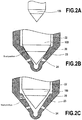
- FIG.2a is a view showing general shape of the forefront part of a needle valve
- FIG.2b is a sectional view showing positional relation between the needle valve and the nozzle body at the forefront part thereof when the injection holes are closed
- FIG.2c is a view as in FIG.2b when the injection holes are opened.
- the fuel injection nozzle means a combination of a nozzle body and a needle valve.
- a needle valve 100 having a two-stage-tapered pointed end part as shown in FIG.2a or having a one-stage-tapered pointed end part not shown in the drawing is widely used.
- the pointed end part of the needle valve 100 is seated on the seat face in the central hollow of the nozzle body 20, the injection holes are closed and fuel is not injected.
- the salient boundary between the two tapered surfaces of the needle valve 100 is seated on the seat face 23 of the nozzle body 20 and fuel is interrupted from flowing to the injection holes.
- the insert tool 30 is inserted into the central hollow of the nozzle body 20 for the purpose of performing abrasive fluid flowing processing under a condition of actual fuel flow as shown in FIG.2c . How the insert tool is utilized for the purpose will be explained hereafter.
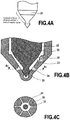
- the conical surface of the insert tool may be formed in the same shape as that of the needle valve 100 or formed in the shape as shown in FIG.4a .
- the insert tool is preferably made of abrasion resistant material in consideration of abrasion by abrasive grains contained in abrasive fluid.
- the insert tool 30 is inserted into the central hollow of the nozzle body 20 such that the central axis of the insert tool coincides with that of the central hollow of the nozzle body 20 and the insert tool 30 is retained at a position at which the seat part of the conical surface of the insert tool departs from the conical seat face in the nozzle body 20 by a height of h along the central axis.
- the height h may be the maximum lift of the needle valve 100 in engine operation or smaller, however, it is more preferable that the height h is a half lift (half of the maximum lift of the needle valve 100) in point of view of reducing processing period.
- FIG.4a and 4b Another adjusting means of axial position of the insert tool 30 is shown in FIG.4a and 4b in which the insert tool 30 is shaped to have a conical surface of a spacer part 25 as a pointed end part to contact the lower end part of the conical seat face in the nozzle body 20.
- positioning of the insert tool is done by the contact of the spacer part 25 to the conical seat face in the nozzle body 20.
- the spacer part 25 is positioned at a position lower the injection holes 24, the fluid passage upstream from the injection holes 24 can be formed in a shape similar to the actual fuel passage in engine operation.
- the insert tool 30 is inserted into the central hollow of the nozzle body 20, the insert tool 30 is retained in position, then the barrel 2 is attached so that the abrasive fluid flow passage 6 of the barrel 2 is communicated with the fuel passage 21 of the nozzle body 20, and the barrel 2 is fixed to the nozzle body concerning rotation position by a dowel pin 70.
- abrasive grains silicon carbide, aluminum oxide, diamond, etc. may be used as has been used conventionally, and grain size is selected in accordance with the targeted diameter of injection hole.
- the medium for carrying abrasive grains it is preferable to select a fluid having viscosity characteristic similar to that of fuel actually used so that abrasive fluid flowing processing is performed in a flow condition similar to that in the actual fuel flow when the abrasive fluid is flowed under pressure under which the abrasive fluid flow becomes a turbulent flow.
- Each of the processing end detection sections 40 includes an abrasive fluid receiver 41, a load detector 42, and a computing unit not shown in the drawing.
- Each of the processing end detection section 40 is provided at the outlet side of each of the injection holes 24 so that weight of abrasive fluid passed through each injection hole can be measured independently.
- the detected weight of the abrasive fluid detected by the load detector 42 is inputted to the computing unit.
- Each of the computing unit sends a signal to the controller 60 when the mass flow rate of the abrasive fluid computed by each computing unit reaches a predetermined value, and the controller 60 connected to each load detector 42 sends a demand signal to each flow blocking section 50.
- the processing end detection sections 40 provided at the outlet side of each of the injection holes 24 use the load detectors 42 for detecting flow rate of abrasive fluid flowing out through each of the injection holes 24 in the embodiment, flow meters of any type which can measure flow rate of abrasive fluid flowing out through the each of the injection holes may be used. Any devices that can measure weight or volume per unit time of abrasive fluid flowing out through each of the injection holes can be adopted.
- procedure in abrasion fluid processing in the second embodiment is the same as that in the first embodiment, an insert tool 30 different in shape from the insert tool 30 in the first embodiment is used in the second embodiment, because the insert tool in the second embodiment must be fixed in rotation position relative to the nozzle body.
- the injection hole processing apparatus shown in FIG.1 can be used for performing the second embodiment of the abrasion fluid processing.
- FIG. 5a is a view showing the shape of the forefront part of the insert tool used in the second embodiment
- FIG. 5b is an enlarged sectional view of a part A 1 in FIG. 1 near injection holes
- FIG.5c is a section along line B 3 -B 3 in FIG.5b .
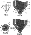
- the insert tool 30 used in the embodiment has a conical end part to be seated on the conical seat face 23 in the nozzle body, and a plurality of passage grooves 31 are formed independently of each other on the conical surface of the insert tool 30, the number of the grooves being the same as that of the injection holes.
- Each of the grooves 31 extends along a generation line of the conical surface of the insert tool so that the annular channel 22 is communicated with each of the injection holes 24 via each of the passage grooves 31.
- the conical surface of the insert tool 30 is formed similar to that of the needle valve 100 and the depth of each of the passage grooves 31 from the conical surface is about the same to maximum height of lift of the needle valve 100 in actual operation of engines.
- each passage groove 31 preferably wider than the diameter of injection hole 24 so that rounding of the entrance corner of the injection hole 24 is affected all around the corner by abrasive fluid flowing through the injection hole 24. It is also preferable that the passage grooves 31 extend below the lower side entrance corner of the injection holes 24 when the insert tool 30 is in position.
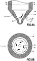
- a nozzle body processed by the method and apparatus of the embodiment will have injection holes of which the entrance corner of each injection hole is rounded with a larger curvature radius in the upstream side than in the entrance corner other than the upstream side, because abrasive fluid flows only through the passage grooves 31 extending along the along the generation lines of the conical surface, so the abrasive fluid flows into each injection hole 24 concentrically from the entrance thereof and the flow is flexed large at the upstream side corner of the entrance of the injection hole.
- concave portions of very small depth not shown in the drawings are formed in the conical seat face 23 in the nozzle body 20 extending downstream along generation lines of the conical seat face to the injection holes 24. That is, the concave portions are formed to reach the injection holes 24 by the most direct way. Therefore, in actual operation of engines, fuel flows to the injection holes 24 easier taking the shortest way, and it is advantageous for increased fuel flow through the injection holes 24.
- insert tool 30 is rotated, it is possible to compose such that the mounting platform 10 to which the nozzle body 20 is fixed is rotated about the central axis of the passage 6 of the barrel 2.
- the injection hole side end part of the insert tool is shaped similar to that of the needle valve and the insert tool is retained at a position that the needle valve is lifted in actual operation of engines when abrasive fluid flowing processing is performed, abrasive fluid flows through a space very similar to that when fuel flows in actual operation of engines at least upstream of the injection holes.
- the entrance corner of each injection hole is rounded with a larger radius of curvature particularly in the upstream region of fuel flow than other regions, and a nozzle body claimed in claim 13 can be obtained.
- the entrance corner of the injection hole can be effectively rounded with a large radius of curvature in a region where flow resistance is large for fuel entering the injection hole, and occurrence of cavitation erosion due to occurrence of separation of fuel flow near the needle valve and injection holes is suppressed and variation in fuel injection characteristic is reduced.
- the entrance corner of the injection hole can be effectively rounded with a large radius of curvature in a region where flow resistance is large for fuel entering the injection hole, and occurrence of cavitation erosion due to occurrence of separation of fuel flow near the needle valve and injection holes is suppressed.
- concave portions of very small depth each of which consists of a straight part and a curved part continuing to the straight part are formed on the conical seat face in the nozzle body in the downstream range from seating position of the conical surface of the needle valve on the conical seat face in the nozzle body in actual operation of engines, and an injection nozzle claimed in claim 15 is obtained.
- the fuel tends to flow swirling influenced by the concave portions to the injection holes, and atomization of a larger angle of spray can be obtained.
Landscapes
- Engineering & Computer Science (AREA)
- Chemical & Material Sciences (AREA)
- Combustion & Propulsion (AREA)
- Mechanical Engineering (AREA)
- General Engineering & Computer Science (AREA)
- Manufacturing & Machinery (AREA)
- Fuel-Injection Apparatus (AREA)
- Finish Polishing, Edge Sharpening, And Grinding By Specific Grinding Devices (AREA)
Claims (15)
- Treibstoffeinspritzdüse, umfassend ein Düsengehäuse mit Einspritzlöchern an dessen Vorderendteil, ein Nadelventil (100), einen ringförmigen Kanal (22) im Düsengehäuse (20), dadurch gekennzeichnet, dass das Düsengehäuse konkave Abschnitte (26) mit sehr kleiner Tiefe an seiner konischen Sitzfläche (23) hat, wobei die konkaven Abschnitte teilweise oder gesamt gebildet sind, um sich entlang Erzeugenden der konischen Sitzfläche zu erstrecken.
- Treibstoffeinspritzdüse nach Anspruch 1, dadurch gekennzeichnet, dass ein Düsenkörper davon Einspritzlöcher an seinem Vorderendteil hat, wobei jedes der Einspritzlöcher (24) eine Eingangsecke hat, die auf einer Seite stark gerundet und auf der anderen Seite schwach gerundet ist, um einen Unterschied in Treibstoffströmungsgeschwindigkeiten des Treibstoffs zu erzeugen, der in das Einspritzloch zwischen dem Eingangsloch, das mit einem großen Radius gerundet ist, und dem, das mit einem kleinen Radius gerundet ist, strömt, wodurch eine Wirbelströmung im Treibstoff erzeugt wird, wenn der Treibstoff in das Einspritzloch (24) strömt.
- Treibstoffeinspritzdüse nach Anspruch 1, dadurch gekennzeichnet, dass ein Düsenkörper davon Einspritzlöcher an seinem Vorderendteil hat, wobei jedes der Einspritzlöcher eine Eingangsecke in seinem stromaufwärts liegenden Bereich des Treibstoffflusses hat, die mit einem größeren Kurvenradius abgerundet ist als jenem in einem anderen als dem stromaufwärts liegenden Bereich des Treibstoffflusses.
- Einspritzlocherzeugungsverfahren für ein Düsengehäuse mit einem Einspritzloch oder -löchern (24), um Eingangslöcher jedes Lochs zu runden, wobei das Düsengehäuse (20) ein Bauteil einer Treibstoffeinspritzdüse gemäß einem der vorangehenden Ansprüche mit einem Nadelventil (100) ist, wobei das Verfahren umfasst
einen Schritt des Einsetzens eines Einsatzwerkzeugs (30), von dem ein Einspritzlochseitenendteil ähnlich dem des Nadelventils (100) geformt ist, und des Zurückhaltens des Einsatzwerkzeugs in einer Position ähnlich der des Nadelventils, wenn es im tatsächlichen Betrieb von Motoren angehoben ist, um Treibstoff zu erlauben, der durch einen Treibstoffdurchgang im Düsengehäuse in einen ringförmigen Kanal (22) im Düsengehäuse (20) eingeleitet wird, aus den Einspritzlöchern eingespritzt zu werden,
einen Schritt des Ausführens einer Flussbearbeitung mit flüssigem Schleifmittel, um die Eingangsecke von mindestens einem der Eingangslöcher durch Einleiten eines flüssigen Schleifmittels (7), das durch mindestens eines der Einspritzlöcher (24) geströmt werden soll, in das Düsengehäuse (20) abzurunden, während ein physischer Wert des flüssigen Schleifmittels gemessen wird, das durch mindestens eines der Einspritzlöcher (24) geströmt wird, und
einen Schritt des Stoppens der Bearbeitung, wenn der physische Wert des flüssigen Schleifmittels, das durch mindestens eines der Einspritzlöcher geströmt wird, einen vorbestimmten Wert erreicht. - Einspritzlocherzeugungsverfahren nach Anspruch 4, dadurch gekennzeichnet, dass
während des Schritts des Einsetzens eines Einsatzwerkzeugs (30) das Einsatzwerkzeug in eine Mittelaussparung des Düsengehäuses (20) eingesetzt wird, so dass das Einsatzwerkzeug in Position gehalten wird,
während des Schritts des Ausführens der Flussbearbeitung mit flüssigem Schleifmittel ein flüssiges Schleifmittel (7) durch die Einspritzlöcher (24) geströmt wird, während ein physischer Wert des flüssigen Schleifmittels gemessen wird, das durch die Eingangslöcher geströmt wird,
während des Schritts des Stoppens die Bearbeitung gestoppt wird, wenn der physische Wert des flüssigen Schleifmittels, das durch die Eingangslöcher geströmt wird, einen vorbestimmten Wert erreicht,
wobei die Flussbearbeitung mit flüssigem Schleifmittel ausgeführt wird, während ein Druck des flüssigen Schleifmittels bei einem konstanten Druck gehalten wird, ein physischer Wert des flüssigen Schleifmittels, das durch die Einspritzlöcher (24) geströmt wird, für jedes Einspritzloch unabhängig durch jedes von Erfassungsmitteln (40) gemessen wird, die an jeder der Einspritzlochauslassöffnungsseiten bereitgestellt sind, um den physischen Wert des flüssigen Schleifmittels zu messen, das aus jeder der Auslassöffnung strömt, jede der Auslassöffnungen blockiert ist, wenn eines von einer Masseströmungsrate oder Volumenströmungsrate von flüssigem Schleifmittel, das aus der Auslassöffnung strömt, einen vorbestimmten Wert erreicht, und das Bearbeiten beendet wird, wenn alle Einspritzlöcher (24) blockiert sind. - Einspritzlocherzeugungsverfahren nach Anspruch 4, dadurch gekennzeichnet, dass
während des Schritts des Einsetzens eines Einsatzwerkzeugs (30) das Einsatzwerkzeug in eine Mittelaussparung des Düsengehäuses (20) eingesetzt wird, so dass das Einsatzwerkzeug in Position gehalten wird,
während des Schritts des Ausführens der Flussbearbeitung mit flüssigem Schleifmittel ein flüssiges Schleifmittel (7) durch die Einspritzlöcher (24) geströmt wird, während ein physischer Wert des flüssigen Schleifmittels gemessen wird, das durch die Eingangslöcher geströmt wird,
und während des Schritts des Stoppens die Bearbeitung von einem der Einspritzlöcher (24) gestoppt wird, wenn der physische Wert des flüssigen Schleifmittels, das durch das eine der Einspritzlöcher geströmt wird, einen vorbestimmten Wert erreicht,
wobei das Einsatzwerkzeug (30) eine konische Fläche hat, die mit einer konischen Sitzfläche (23) im Düsengehäuse in Kontakt gebracht werden kann, Durchgangskerben (31) unabhängig voneinander von der gleichen Zahl wie jene der Einspritzlöcher (24) auf der konischen Fläche gebildet sind, so dass sich jede Durchgangskerbe (31) entlang einer Erzeugenden der konischen Fläche erstreckt, so dass ihr stromaufwärtsseitiges Ende mit einem ringförmigen Kanal (22) verbunden ist, der mit einem Treibstoffdurchgang (21) im Düsengehäuse (20) verbunden ist, und ihr anderes, stromabwärtsseitiges Ende mit jedem der Einspritzlöcher verbunden ist, wenn das Einsatzwerkzeug in eine Mittelaussparung des Düsengehäuses eingesetzt ist, wobei seine Drehungsposition relativ zum Düsengehäuse an einer ermittelten Drehungsposition gehalten wird und wobei seine konische Fläche mit der konischen Sitzfläche (23) im Düsengehäuse (20) in Kontakt gebracht wird, das Einsatzwerkzeug (30) an seiner ermittelten Position gehalten wird, eine Flussbearbeitung mit flüssigem Schleifmittel durch Einleiten von flüssigem Schleifmittel in das Düsengehäuse, das durch die Einspritzlöcher geströmt werden soll, ausgeführt wird, während ein Druck des flüssigen Schleifmittels bei einem konstanten Druck gehalten wird, der physische Wert des flüssigen Schleifmittels, das durch die Einspritzlöcher ausströmt, für jedes Einspritzloch durch jedes von Erfassungsmitteln (40), die bei jeder von Einspritzlochauslassöffnungsseiten bereitgestellt sind, unabhängig gemessen wird, um den physischen Wert des flüssigen Schleifmittels zu messen, das aus jeder Auslassöffnung ausströmt, jede der Auslassöffnungen blockiert wird, wenn die Masseströmungsrate oder Volumenströmungsrate von flüssigem Schleifmittel, die durch relevante der Erfassungsmittel berechnet wird, einen vorbestimmten Wert erreicht, und die Bearbeitung beendet wird, wenn alle Einspritzlöcher (24) blockiert sind. - Einspritzlocherzeugungsverfahren nach Anspruch 4, dadurch gekennzeichnet, dass
während des Schritts des Einsetzens eines Einsatzwerkzeugs (30) das Einsatzwerkzeug in eine Mittelaussparung des Düsengehäuses (20) eingesetzt wird, so dass das Einsatzwerkzeug in Position gehalten wird,
während des Schritts des Ausführens der Flussbearbeitung mit flüssigem Schleifmittel ein flüssiges Schleifmittel durch die Einspritzlöcher (24) geströmt wird, während der physische Wert des flüssigen Schleifmittels (7), das durch die Einspritzlöcher geströmt wird, gemessen wird und während des Schritts des Stoppens die Bearbeitung von einem der Einspritzlöcher gestoppt wird, wenn der physische Wert des flüssigen Schleifmittels, das durch eines der Einspritzlöcher (24) geströmt wird, einen vorbestimmten Wert erreicht, wobei das Einsatzwerkzeug (30) eine konische Fläche hat, die mit einer konischen Sitzfläche (23) im Düsengehäuse in Kontakt gebracht werden kann, Durchgangskerben (31) unabhängig voneinander in der selben Zahl wie jene der Einspritzlöcher auf der konischen Fläche geformt sind, so dass jede Durchgangskerbe einen geraden Teil (31 a), der sich entlang einer Erzeugenden der konischen Fläche erstreckt, und einen gekrümmten Teil (31 b), der sich zum geraden Teil fortsetzt, hat, so dass ihr stromaufwärtsseitiges Ende mit einem ringförmigen Kanal (22) verbunden ist, der mit einem Treibstoffdurchgang (21) im Düsengehäuse (20) verbunden ist, und ihr anderes, stromabwärtsseitiges Ende, das heißt eine stromabwärts liegende Seite des gekrümmten Teils (31 b) der Durchgangskerbe, mit jedem der Einspritzlöcher (24) verbunden ist, wenn das Einsatzwerkzeug (30) in eine Mittelaussparung des Düsengehäuses eingesetzt wird, wobei seine Drehungsposition relativ zum Düsengehäuse (20) bei einer vorbestimmten Drehungsposition gehalten wird und wobei seine konische Fläche mit der konischen Sitzfläche (23) im Düsengehäuse in Kontakt gebracht wird, das Einsatzwerkzeug an seiner ermittelten Position gehalten wird, eine Flussbearbeitung mit flüssigem Schleifmittel durch Einleiten von flüssigem Schleifmittel in das Düsengehäuse, das durch die Einspritzlöcher (24) geströmt werden soll, ausgeführt wird, während ein Druck des flüssigen Schleifmittels bei einem konstanten Druck gehalten wird, der physische Wert des flüssigen Schleifmittels, das durch jedes der Einspritzlöcher (24) geströmt wird, für jedes Einspritzloch durch jedes von Erfassungsmitteln, die bei jeder von Einspritzlochauslassöffnungsseiten bereitgestellt sind, unabhängig gemessen wird, um den physischen Wert des flüssigen Schleifmittels zu messen, das aus jeder Auslassöffnung ausströmt, jede der Auslassöffnungen blockiert wird, wenn die Masseströmungsrate oder Volumenströmungsrate von flüssigem Schleifmittel, die durch relevante der Erfassungsmittel (40) berechnet wird, einen vorbestimmten Wert erreicht, und die Bearbeitung beendet wird, wenn alle Einspritzlöcher (24) blockiert sind. - Einspritzlocherzeugungsverfahren nach Anspruch 4, dadurch gekennzeichnet, dass
während des Schritts des Einsetzens eines Einsatzwerkzeugs (30) das Einsatzwerkzeug in eine Mittelaussparung des Düsengehäuses (20) eingesetzt wird, so dass das Einsatzwerkzeug in Position gehalten wird,
während des Schritts des Ausführens der Flussbearbeitung mit flüssigem Schleifmittel ein flüssiges Schleifmittel (7) durch jedes der Einspritzlöcher (24) geströmt wird, während der physische Wert des flüssigen Schleifmittels, das durch die Einspritzlöcher (24) geströmt wird, gemessen wird,
während des Schritts des Stoppens die Bearbeitung gestoppt wird, wenn der physische Wert des flüssigen Schleifmittels, das durch eines der Einspritzlöcher (24) geströmt wird, einen vorbestimmten Wert erreicht, und
das Verfahren des Weiteren einen Schritt des Drehens des Einsatzwerkzeugs (30) umfasst, um die Bearbeitung von eines anderen der Einspritzlöcher (24) auszuführen, wobei das Einsatzwerkzeug eine konische Fläche hat, die mit einer konischen Sitzfläche (23) im Düsengehäuse (20) in Kontakt gebracht werden kann, eine Durchgangskerbe (31) auf der konischen Fläche gebildet ist, so dass sich die Durchgangskerbe entlang einer Erzeugenden der konischen Fläche erstreckt, so dass ihr stromaufwärtsseitiges Ende mit einem ringförmigen Kanal (22) verbunden ist, der mit einem Treibstoffdurchgang (21) im Düsengehäuse (20) verbunden ist, und ihr anderes, stromabwärtsseitiges Ende mit einem der Einspritzlöcher (24) verbunden ist, wenn das Einsatzwerkzeug in eine Mittelaussparung des Düsengehäuses eingesetzt wird, wobei seine Drehungsposition relativ zum Düsengehäuse an einer ermittelten Drehungsposition gehalten wird und wobei seine konische Fläche mit der konischen Sitzfläche (23) im Düsengehäuse (20) in Kontakt gebracht wird, das Einsatzwerkzeug (30) an seiner ermittelten Position gehalten wird, eine Flussbearbeitung mit flüssigem Schleifmittel durch Einleiten von flüssigem Schleifmittel (7) in das Düsengehäuse (20), das durch die Einspritzlöcher (24) geströmt werden soll, ausgeführt wird, während der Druck des flüssigen Schleifmittels bei einem konstanten Druck gehalten wird, der physische Wert des flüssigen Schleifmittels, das durch das Einspritzloch ausströmt, durch ein Erfassungsmittel (40) berechnet wird, zum Messen des physischen Werts des flüssigen Schleifmittels, das aus jeder der Auslassöffnungen ausströmt, die Bearbeitung des einen der Einspritzlöcher (24) gestoppt wird, wenn die Masseströmungsrate oder Volumenströmungsrate von flüssigem Schleifmittel, das aus der Auslassöffnung des Einspritzloches ausströmt, einen vorbestimmten Wert erreicht, dann das Einsatzwerkzeug (30) gedreht wird, so dass die Durchgangskerbe (31) mit einem anderen der Einspritzlöcher (24) in Verbindung gebracht wird, und die Bearbeitung des anderen Einspritzlochs auf dieselbe Weise ausgeführt wird, wodurch die Bearbeitung wiederholt wird, bis alle der Einspritzlöcher bearbeitet sind. - Einspritzlocherzeugungsverfahren nach Anspruch 4, dadurch gekennzeichnet, dass
während des Schritts des Einsetzens eines Einsatzwerkzeugs (30) das Einsatzwerkzeug in eine Mittelaussparung des Düsengehäuses eingesetzt wird, so dass das Einsatzwerkzeug in Position gehalten wird,
während des Schritts des Ausführens der Flussbearbeitung mit flüssigem Schleifmittel das flüssige Schleifmittel (7) durch eines der Einspritzlöcher (24) geströmt wird, während der physische Wert des flüssigen Schleifmittels, das durch die Einspritzlöcher (24) geströmt wird, gemessen wird,
während des Schritts des Stoppens die Bearbeitung gestoppt wird, wenn der physische Wert des flüssigen Schleifmittels, das durch eines der Einspritzlöcher geströmt wird, einen vorbestimmten Wert erreicht, und
das Verfahren des Weiteren einen Schritt des Drehens des Einsatzwerkzeugs (30) umfasst, um die Bearbeitung von einem anderen der Einspritzlöcher (24) auszuführen,
wobei das Einsatzwerkzeug eine konische Fläche hat, die mit einer konischen Sitzfläche (23) im Düsengehäuse (20) in Kontakt gebracht werden kann, eine Durchgangskerbe (31) auf der konischen Fläche gebildet ist, so dass die Durchgangskerbe einen geraden Teil (31 a), der sich entlang einer Erzeugenden der konischen Fläche erstreckt, und einen gekrümmten Teil (31 b), der sich zum geraden Teil fortsetzt, hat, so dass ihr stromaufwärtsseitiges Ende mit einem ringförmigen Kanal (22) verbunden ist, der mit einem Treibstoffdurchgang (21) im Düsengehäuse (20) verbunden ist, und ihr anderes stromabwärtsseitiges Ende, das heißt eine stromabwärts liegende Seite des gekrümmten Teils (31 b) der Durchgangskerbe mit jedem der Einspritzlöcher (24) verbunden ist, wenn das Einsatzwerkzeug (30) in eine Mittelaussparung des Düsengehäuses (20) eingesetzt wird, wobei seine Drehungsposition relativ zum Düsengehäuse an einer ermittelten Drehungsposition gehalten wird und wobei seine konische Fläche mit der konischen Sitzfläche (23) im Düsengehäuse (20) in Kontakt gebracht wird, das Einsatzwerkzeug (30) an seiner ermittelten Position gehalten wird, eine Flussbearbeitung mit flüssigem Schleifmittel durch Einleiten von flüssigem Schleifmittel (7), das durch die Einspritzlöcher geströmt werden soll, in das Düsengehäuse (20) ausgeführt wird, während der Druck des flüssigen Schleifmittels bei einem konstanten Druck gehalten wird, der physische Wert des flüssigen Schleifmittels, das durch das Einspritzloch ausströmt, durch ein Erfassungsmittel (40) berechnet wird, zum Messen des physischen Werts des flüssigen Schleifmittels, das aus jeder der Auslassöffnungen ausströmt, die Bearbeitung des einen der Einspritzlöcher gestoppt wird, wenn die Masseströmungsrate oder Volumenströmungsrate von flüssigem Schleifmittel, das aus der Auslassöffnung des Einspritzloches ausströmt, einen vorbestimmten Wert erreicht, dann das Einsatzwerkzeug (30) gedreht wird, so dass die Durchgangskerbe (31) mit einem anderen der Einspritzlöcher (24) in Verbindung gebracht wird, und die Bearbeitung des anderen Einspritzlochs auf dieselbe Weise ausgeführt wird, wodurch die Bearbeitung wiederholt wird, bis alle der Einspritzlöcher bearbeitet sind. - Einspritzlochzerspanungsvorrichtung eines Düsengehäuses mit einem Einspritzloch oder -löchern (24) um eine Eingangsecke von jedem Loch abzurunden, wobei das Düsengehäuse (20) ein Bauteil einer Treibstoffeinspritzdüse nach Anspruch 1 mit einem Nadelventil (100) ist, wobei die Vorrichtung einen Versorgungsabschnitt für flüssiges Schleifmittel (1), eine Montageplattform (10), ein Einsatzwerkzeug (30), einen Rückhalteteil zum Zurückhalten des Einsatzwerkzeugs, Erfassungsabschnitte (40) zum Erfassen eines Zeitpunkts zum Stoppen der Flussbearbeitung mit flüssigem Schleifmittel jedes der Einspritzlöcher, Flussblockierungsabschnitte (50) und ein Steuergerät (60) enthält, wobei das Einsatzwerkzeug einen Einspritzlochseitenendteil hat, der so geformt ist, dass er dem Nadelventil ähnlich ist, und das andere Ende des Einsatzwerkzeugs (30) einen Flanschteil hat, so dass das Einsatzwerkzeug in einer Position ähnlich jener des Nadelventils (100) gehalten wird, wenn es im tatsächlichen Betrieb von Motoren angehoben wird, um Treibstoff zu erlauben, der durch einen Treibstoffdurchgang (21) im Düsengehäuse (20) in einen ringförmigen Kanal (22) im Düsengehäuse eingeleitet wird, aus den Einspritzlöchern eingespritzt zu werden.
- Einspritzlochzerspanungsvorrichtung eines Düsengehäuses nach Anspruch 10, wobei die Bearbeitungsstoppzeitpunkt-Erfassungsabschnitte (40) physische Wertdetektoren (42) zum Erfassen des physischen Werts von flüssigem Schleifmittel, das durch jedes der Einspritzlöcher strömt, und Recheneinheiten zum Berechnen der Masseströmungsrate oder Volumenströmungsrate von flüssigem Schleifmittel, das aus jedem der Einspritzlöcher (24) ausströmt, enthalten, wobei jeder der Bearbeitungsstoppzeitpunkt-Erfassungsabschnitte bei jeder der Einspritzlochauslassöffnungsseiten bereitgestellt ist.
- Einspritzlochzerspanungsvorrichtung nach Anspruch 10, dadurch gekennzeichnet, dass
das Einsatzwerkzeug (30) eine konische Fläche hat, ähnlich jener des Nadelventils (100), Durchgangskerben (31) unabhängig voneinander von der gleichen Zahl wie die der Einspritzlöcher (24) auf der konischen Fläche gebildet sind, so dass sich jede Durchgangskerbe entlang einer Erzeugenden der konischen Fläche erstreckt, so dass ihr stromaufwärtsseitiges Ende mit einem ringförmigen Kanal (22) verbunden ist, der mit einem Treibstoffdurchgang (21) im Düsengehäuse (20) verbunden ist, und ihr anderes, stromabwärtsseitiges Ende mit jedem der Einspritzlöcher verbunden ist, wenn das Einsatzwerkzeug in eine Mittelaussparung des Düsengehäuses eingesetzt wird, wobei seine Drehungsposition relativ zum Düsengehäuse an einer ermittelten Drehungsposition gehalten wird und wobei seine konische Fläche mit der konischen Sitzfläche (23) im Düsengehäuse (20) in Kontakt gebracht wird, die Bearbeitungsstoppzeitpunkt-Erfassungsabschnitte (40) physische Wertdetektoren (42) zum Erfassen des physischen Werts von flüssigem Schleifmittel, das durch jedes der Einspritzlöcher strömt, und Recheneinheiten vom Berechnen der Masseströmungsrate oder Volumenströmungsrate von flüssigem Schleifmittel, das aus jedem der Einspritzlöcher ausströmt, enthalten, wobei jeder der Bearbeitungsstoppzeitpunkt-Erfassungsabschnitte an jeder von Einspritzlochauslassöffnungsseiten bereitgestellt ist. - Einspritzlochzerspanungsvorrichtung nach Anspruch 10, dadurch gekennzeichnet, dass
das Einsatzwerkzeug (30) eine konische Fläche hat, die mit einer konischen Sitzfläche (23) im Düsengehäuse (20) in Kontakt gebracht werden kann, Durchgangskerben (31) unabhängig voneinander von der gleichen Zahl wie jene der Einspritzlöcher (24) auf der konischen Fläche gebildet sind, so dass jede Durchgangskerbe (31) einen geraden Teil (31a), der sich entlang einer Erzeugenden der konischen Fläche erstreckt, und einen gekrümmten Teil (31 b), der sich zum geraden Teil fortsetzt, hat, so dass ihr stromaufwärtsseitiges Ende mit einem ringförmigen Kanal (22) verbunden ist, der mit einem Treibstoffdurchgang (21) im Düsengehäuse (20) verbunden ist, und ihr anderes, stromabwärtsseitiges Ende, das heißt stromabwärtsseitig des gekrümmten Teils der Durchgangskerbe (31), mit jedem der Einspritzlöcher verbunden ist, wenn das Einsatzwerkzeug in eine Mittelaussparung des Düsengehäuses eingesetzt wird, wobei seine Drehungsposition relativ zum Düsengehäuse an einer ermittelten Drehungsposition gehalten wird und wobei seine konische Fläche mit der konischen Sitzfläche (23) im Düsengehäuse (20) in Kontakt gebracht wird, die Bearbeitungsstoppzeitpunkt-Erfassungsabschnitte (40) physische Wertdetektoren (42) zum Erfassen des physischen Werts des flüssigen Schleifmittels, das durch jedes der Einspritzlöcher strömt, und Recheneinheiten zum Berechnen der Masseströmungsrate oder Volumenströmungsrate von flüssigem Schleifmittel, das aus jedem der Einspritzlöcher (24) ausströmt, enthalten, wobei jeder der Bearbeitungsstoppzeitpunkt-Erfassungsabschnitte (40) an jeder von Einspritzlochauslassöffnungsseiten bereitgestellt ist. - Einspritzlochzerspanungsvorrichtung nach Anspruch 10, dadurch gekennzeichnet, dass das Einsatzwerkzeug (30) eine konische Fläche ähnlich jener des Nadelventils hat, eine Durchgangskerbe (31) auf der konischen Fläche gebildet ist, so dass sich die Durchgangskerbe entlang einer Erzeugenden der konischen Fläche erstreckt, so dass ihr stromaufwärtsseitiges Ende mit einem ringförmigen Kanal (22) verbunden ist, der mit einem Treibstoffdurchgang (21) im Düsengehäuse (20) verbunden ist, und ihr anderes, stromabwärtsseitige Ende mit einem der Einspritzlöcher (24) verbunden ist, wenn das Einsatzwerkzeug in eine Mittelaussparung des Düsengehäuses eingesetzt wird, wobei seine Drehungsposition relativ zum Düsengehäuse an einer ermittelten Drehungsposition gehalten wird und wobei seine konische Fläche mit der konischen Sitzfläche im Düsengehäuse in Kontakt gebracht wird, ein Drehungsmittel (80) zum Drehen des Einsatzwerkzeugs (30) um seine Mittelachse oder zum Drehen der Montageplattform (10), an der das Düsengehäuse (20) fixiert ist, um die Mittelachse eines Versorgungsdurchgangs im Versorgungsabschnitt flüssigen Schleifmittels zum Zuleiten von flüssigem Schleifmittel zum Treibstoffdurchgang in das Düsengehäuse durch einen ermittelten Drehungswinkel bereitgestellt ist, und der Bearbeitungsstoppzeitpunkt-Erfassungsabschnitt (40) einen physischen Wertdetektor (42) zum Erfassen des physischen Werts von flüssigem Schleifmittel, das durch eines der Einspritzlöcher strömt, und eine Recheneinheit zum Berechnen der Masseströmungsrate oder Volumenströmungsrate von flüssigem Schleifmittel, das aus dem relevanten Einspritzloch ausströmt, umfasst.
- Einspritzlochzerspanungsvorrichtung nach Anspruch 10, dadurch gekennzeichnet, dass das Einsatzwerkzeug eine konische Fläche ähnlich jener des Nadelventils (100) hat, eine Durchgangskerbe (31) auf der konischen Fläche gebildet ist, so dass die Durchgangskerbe einen geraden Teil (31 a), der sich entlang einer Erzeugenden der konischen Fläche erstreckt, und einen gekrümmten Teil (31 b), der sich zum geraden Teil fortsetzt, hat, so dass ihr stromaufwärtsseitiges Ende mit einem ringförmigen Kanal (22) verbunden ist, der mit einem Treibstoffdurchgang (21) im Düsengehäuse (20) verbunden ist, und ihr anderes, stromabwärtsseitiges Ende, das heißt stromabwärtsseitig des gekrümmten Teils der Durchgangskerbe (31), mit jedem der Einspritzlöcher (24) verbunden ist, wenn das Einsatzwerkzeug in eine Mittelaussparung des Düsengehäuses eingesetzt wird, wobei seine Drehungsposition relativ zum Düsengehäuse an einer ermittelten Drehungsposition gehalten wird und wobei seine konische Fläche mit der konischen Sitzfläche im Düsengehäuse in Kontakt gebracht wird, ein Drehungsmittel (80) zum Drehen des Einsatzwerkzeugs um seine Mittelachse oder zum Drehen der Montageplattform (10), an der das Düsengehäuse fixiert ist, um die Mittelachse eines Versorgungsdurchgangs im Versorgungsabschnitt für flüssiges Schleifmittel zum Zuleiten von flüssigem Schleifmittel zum Treibstoffdurchgang (21) im Düsengehäuse (20) um einen ermittelten Drehungswinkel bereitgestellt ist und der Bearbeitungsstoppzeitpunkt-Erfassungsabschnitt (40) einen physischen Wertdetektor (42) zum Erfassen des physischen Werts von flüssigem Schleifmittel, das durch eines der Einspritzlöcher strömt, und eine Recheneinheit zum Berechnen der Masseströmungsrate oder Volumenströmungsrate von flüssigem Schleifmittel, das aus dem relevanten Einspritzloch ausströmt, enthält.
Applications Claiming Priority (1)
| Application Number | Priority Date | Filing Date | Title |
|---|---|---|---|
| JP2006248979A JP2008068360A (ja) | 2006-09-14 | 2006-09-14 | ノズルボディの噴孔加工方法、噴孔加工装置、及びそれらを用いて作製された燃料噴射ノズル |
Publications (3)
| Publication Number | Publication Date |
|---|---|
| EP1900935A2 EP1900935A2 (de) | 2008-03-19 |
| EP1900935A3 EP1900935A3 (de) | 2009-08-05 |
| EP1900935B1 true EP1900935B1 (de) | 2017-06-07 |
Family
ID=38750648
Family Applications (1)
| Application Number | Title | Priority Date | Filing Date |
|---|---|---|---|
| EP07115245.8A Not-in-force EP1900935B1 (de) | 2006-09-14 | 2007-08-29 | Verfahren zur Bearbeitung eines Injektionslochs in einem Düsenelement, Vorrichtung dafür sowie mit diesem Verfahren hergestellte Brennstoffeinspritzdüse und -vorrichtung |
Country Status (3)
| Country | Link |
|---|---|
| US (1) | US8136745B2 (de) |
| EP (1) | EP1900935B1 (de) |
| JP (1) | JP2008068360A (de) |
Families Citing this family (19)
| Publication number | Priority date | Publication date | Assignee | Title |
|---|---|---|---|---|
| JP2009226507A (ja) * | 2008-03-19 | 2009-10-08 | Denso Corp | 流体研磨方法 |
| CN102179286B (zh) * | 2011-04-11 | 2012-11-07 | 上海大学 | 无磨损挤压研磨浆料压力发生装置及方法 |
| AT512423A1 (de) * | 2012-02-07 | 2013-08-15 | Bosch Gmbh Robert | Einspritzdüse zum einspritzen von medien in den brennraum einer brennkraftmaschine |
| CN102990506B (zh) * | 2012-12-04 | 2014-12-03 | 中国第一汽车股份有限公司无锡油泵油嘴研究所 | 喷油嘴喷孔的挤压研磨装置及方法 |
| US20140175192A1 (en) * | 2012-12-21 | 2014-06-26 | Quantlogic Corporation | Mixed-mode fuel injector with a variable orifice |
| CN104588962B (zh) * | 2014-12-03 | 2017-08-04 | 中国第一汽车股份有限公司无锡油泵油嘴研究所 | 一种发动机孔式喷油嘴单孔挤压研磨装置及使用方法 |
| GB201511767D0 (en) * | 2015-07-06 | 2015-08-19 | Delphi Int Operations Lux Srl | Nozzle tip manufacturing |
| DE102016211676A1 (de) * | 2016-06-29 | 2018-01-04 | Robert Bosch Gmbh | Injektor mit Entlastungsnut |
| CN107891372A (zh) * | 2017-10-18 | 2018-04-10 | 国营第六六厂 | 针阀体油道孔和喷孔磨料挤压研磨连接装置 |
| CN108637717B (zh) * | 2018-05-21 | 2020-06-02 | 国营第六一六厂 | 一种精确快速液力挤压阀座斜孔的加工夹具 |
| US20220032425A1 (en) * | 2018-09-24 | 2022-02-03 | Basf Se | Method for surface processing of a component by flow grinding |
| JP7066000B2 (ja) | 2018-10-26 | 2022-05-12 | 日立Astemo株式会社 | 燃料噴射弁 |
| CN114248203B (zh) * | 2020-09-24 | 2023-04-07 | 中国石油天然气集团有限公司 | 旋流切割工具 |
| CN113083530B (zh) * | 2021-03-01 | 2022-08-16 | 武汉大学 | 一种中心体位置可连续调节的空化喷嘴 |
| US12078136B2 (en) * | 2022-05-20 | 2024-09-03 | Caterpillar Inc. | Fuel injector nozzle assembly including needle having flow guiding tip for directing fuel flow |
| CN114734307B (zh) * | 2022-06-13 | 2022-09-02 | 中国航发上海商用航空发动机制造有限责任公司 | 具有转弯结构的微细内流道的表面光整方法 |
| CN115876265B (zh) * | 2023-02-16 | 2023-05-16 | 西安成立航空制造有限公司 | 一种航空发动机喷嘴流量检测装置 |
| US20250369410A1 (en) * | 2024-06-04 | 2025-12-04 | Caterpillar Inc. | Fuel injector and nozzle assembly configured for limiting cavitation damage |
| CN119567103B (zh) * | 2024-11-13 | 2025-10-03 | 中国航发南方工业有限公司 | 一种航空发动机燃油喷嘴流道液态磨粒流光整加工方法 |
Family Cites Families (18)
| Publication number | Priority date | Publication date | Assignee | Title |
|---|---|---|---|---|
| DE2920100A1 (de) * | 1979-05-18 | 1980-11-27 | Bosch Gmbh Robert | Kraftstoffeinspritzduese mit gesteuertem einspritzquerschnitt fuer brennkraftmaschinen |
| US5029759A (en) * | 1989-11-17 | 1991-07-09 | Cummins Engine Company, Inc. | Curved hole machining method and fuel injector formed thereby |
| JPH0752022A (ja) * | 1993-08-19 | 1995-02-28 | Toyota Motor Corp | 砥粒流動体を用いた加工方法及びその加工装置 |
| DE19507171C1 (de) * | 1995-03-02 | 1996-08-14 | Bosch Gmbh Robert | Kraftstoffeinspritzventil für Brennkraftmaschinen |
| DE19507188C1 (de) * | 1995-03-02 | 1996-08-14 | Bosch Gmbh Robert | Kraftstoffeinspritzventil für Brennkraftmaschinen |
| JPH0914087A (ja) * | 1995-06-23 | 1997-01-14 | Toyota Motor Corp | 燃料噴射ノズルのノズル特性調整方法 |
| ATE346896T1 (de) | 1995-08-04 | 2006-12-15 | Dynetics Llc | Abrasive suspension |
| JP3757453B2 (ja) | 1996-02-07 | 2006-03-22 | 株式会社デンソー | 燃料噴射ノズルの噴孔加工方法 |
| EP0809017A1 (de) * | 1996-05-22 | 1997-11-26 | Steyr-Daimler-Puch Aktiengesellschaft | Zweistufige Kraftstoffeinspritzdüse für Brennkraftmaschinen |
| JPH109095A (ja) * | 1996-06-21 | 1998-01-13 | Zexel Corp | 燃料噴射ノズル |
| US6132482A (en) | 1996-11-12 | 2000-10-17 | Dynetics Corporation | Abrasive liquid slurry for polishing and radiusing a microhole |
| JPH10337649A (ja) | 1997-06-05 | 1998-12-22 | Nissan Motor Co Ltd | 砥粒流動体を用いたインジェクタノズルの加工方法及びその装置 |
| JPH11197946A (ja) | 1998-01-13 | 1999-07-27 | Isuzu Motors Ltd | 砥粒流動電解研磨加工工法及びその加工装置 |
| DE19931890A1 (de) * | 1999-07-08 | 2001-01-18 | Siemens Ag | Düsenkörper für eine Kraftstoffeinspritzdüse mit optimierter Spritzlochkanalgeometrie |
| JP2001347458A (ja) * | 2000-06-05 | 2001-12-18 | Nissan Motor Co Ltd | 噴孔加工装置 |
| JP3994801B2 (ja) * | 2002-06-18 | 2007-10-24 | トヨタ自動車株式会社 | 燃料噴射弁本体の噴孔部加工方法 |
| DE10353168A1 (de) * | 2003-11-14 | 2005-06-23 | Robert Bosch Gmbh | Verfahren und Vorrichtung zum hydroerosiven Verrunden von Bohrungsübergängen |
| DE202006005889U1 (de) * | 2006-04-11 | 2006-07-20 | Robert Bosch Gmbh | Vorrichtung zum hydroerosiven Verrunden von Bohrungsübergängen zu Einspritzöffnungen in Kraftstoffeinspritzdüsen |
-
2006
- 2006-09-14 JP JP2006248979A patent/JP2008068360A/ja active Pending
-
2007
- 2007-06-29 US US11/822,026 patent/US8136745B2/en not_active Expired - Fee Related
- 2007-08-29 EP EP07115245.8A patent/EP1900935B1/de not_active Not-in-force
Also Published As
| Publication number | Publication date |
|---|---|
| US8136745B2 (en) | 2012-03-20 |
| EP1900935A3 (de) | 2009-08-05 |
| JP2008068360A (ja) | 2008-03-27 |
| US20080067268A1 (en) | 2008-03-20 |
| EP1900935A2 (de) | 2008-03-19 |
Similar Documents
| Publication | Publication Date | Title |
|---|---|---|
| EP1900935B1 (de) | Verfahren zur Bearbeitung eines Injektionslochs in einem Düsenelement, Vorrichtung dafür sowie mit diesem Verfahren hergestellte Brennstoffeinspritzdüse und -vorrichtung | |
| EP0957262B1 (de) | Kraftstoffinjektor | |
| US8166807B2 (en) | Apparatus and methods for testing a fuel injector nozzle | |
| CN103206326B (zh) | 配备有计量伺服阀的内燃机用燃料喷射器 | |
| CN101294530B (zh) | 带有平衡测量伺服阀的内燃机燃料喷射器 | |
| CA1053521A (en) | Fuel injection valves and their manufacture | |
| US20030057299A1 (en) | Fuel injection nozzle | |
| US8905333B1 (en) | Diesel injector and method utilizing focused supercavitation to reduce spray penetration length | |
| US20240175364A1 (en) | Gas turbine engines and methods associated therewith | |
| JP4088493B2 (ja) | 燃料噴射弁 | |
| EP2333307A1 (de) | Kraftstoffeinspritzventil für einen verbrennungsmotor und herstellungsverfahren dafür | |
| JP2001182641A (ja) | 燃料噴射ノズルおよびその製造方法 | |
| Kilic et al. | Influence of nozzle parameters on single jet flow quantities of multi-hole diesel injection nozzles | |
| Diver et al. | Improving the geometry and quality of a micro-hole fuel injection nozzle by means of hydroerosive grinding | |
| JP2013519027A (ja) | 針弁のための針 | |
| KR20190020703A (ko) | 통로 개구의 테이퍼된 유입 영역을 구비한 유체 분사용 분사기 | |
| KR20100002199A (ko) | 내연 기관 엔진을 위한 밸런스된 타입의 계측 서보밸브를 구비한 연료 분사기 | |
| Sooriyakumaran | Experimental study of profile losses in three transonic turbine cascades | |
| JP2008223635A (ja) | 燃料噴射弁の製造方法 | |
| CN212177296U (zh) | 一种火箭发动机及其用流量孔板 | |
| US12006922B1 (en) | Precision manifold for an ion thruster using characterized flow restrictors | |
| JP4214971B2 (ja) | 流体噴射弁の流量調整方法 | |
| GB2472511A (en) | Pressure measurement for flow metering device | |
| JP2002327664A (ja) | 燃料噴射弁における噴霧形状の解析方法 | |
| Nikparto et al. | Experimental Investigation of Film Cooling Effectiveness of a Highly Loaded Turbine Blade Under Steady and Periodic Unsteady Flow Conditions |
Legal Events
| Date | Code | Title | Description |
|---|---|---|---|
| PUAI | Public reference made under article 153(3) epc to a published international application that has entered the european phase |
Free format text: ORIGINAL CODE: 0009012 |
|
| AK | Designated contracting states |
Kind code of ref document: A2 Designated state(s): AT BE BG CH CY CZ DE DK EE ES FI FR GB GR HU IE IS IT LI LT LU LV MC MT NL PL PT RO SE SI SK TR |
|
| AX | Request for extension of the european patent |
Extension state: AL BA HR MK YU |
|
| PUAL | Search report despatched |
Free format text: ORIGINAL CODE: 0009013 |
|
| AK | Designated contracting states |
Kind code of ref document: A3 Designated state(s): AT BE BG CH CY CZ DE DK EE ES FI FR GB GR HU IE IS IT LI LT LU LV MC MT NL PL PT RO SE SI SK TR |
|
| AX | Request for extension of the european patent |
Extension state: AL BA HR MK RS |
|
| 17P | Request for examination filed |
Effective date: 20100204 |
|
| AKX | Designation fees paid |
Designated state(s): DE FR GB |
|
| GRAP | Despatch of communication of intention to grant a patent |
Free format text: ORIGINAL CODE: EPIDOSNIGR1 |
|
| STAA | Information on the status of an ep patent application or granted ep patent |
Free format text: STATUS: GRANT OF PATENT IS INTENDED |
|
| INTG | Intention to grant announced |
Effective date: 20161223 |
|
| GRAS | Grant fee paid |
Free format text: ORIGINAL CODE: EPIDOSNIGR3 |
|
| GRAA | (expected) grant |
Free format text: ORIGINAL CODE: 0009210 |
|
| STAA | Information on the status of an ep patent application or granted ep patent |
Free format text: STATUS: THE PATENT HAS BEEN GRANTED |
|
| AK | Designated contracting states |
Kind code of ref document: B1 Designated state(s): DE FR GB |
|
| REG | Reference to a national code |
Ref country code: GB Ref legal event code: FG4D |
|
| GRAA | (expected) grant |
Free format text: ORIGINAL CODE: 0009210 |
|
| REG | Reference to a national code |
Ref country code: DE Ref legal event code: R096 Ref document number: 602007051225 Country of ref document: DE |
|
| REG | Reference to a national code |
Ref country code: DE Ref legal event code: R097 Ref document number: 602007051225 Country of ref document: DE |
|
| PLBE | No opposition filed within time limit |
Free format text: ORIGINAL CODE: 0009261 |
|
| STAA | Information on the status of an ep patent application or granted ep patent |
Free format text: STATUS: NO OPPOSITION FILED WITHIN TIME LIMIT |
|
| 26N | No opposition filed |
Effective date: 20180308 |
|
| REG | Reference to a national code |
Ref country code: FR Ref legal event code: ST Effective date: 20180430 |
|
| PG25 | Lapsed in a contracting state [announced via postgrant information from national office to epo] |
Ref country code: FR Free format text: LAPSE BECAUSE OF NON-PAYMENT OF DUE FEES Effective date: 20170831 |
|
| REG | Reference to a national code |
Ref country code: DE Ref legal event code: R082 Ref document number: 602007051225 Country of ref document: DE Representative=s name: CBDL PATENTANWAELTE, DE Ref country code: DE Ref legal event code: R081 Ref document number: 602007051225 Country of ref document: DE Owner name: MITSUBISHI HEAVY INDUSTRIES ENGINE & TURBOCHAR, JP Free format text: FORMER OWNER: MITSUBISHI HEAVY INDUSTRIES, LTD., TOKYO, JP |
|
| REG | Reference to a national code |
Ref country code: GB Ref legal event code: 732E Free format text: REGISTERED BETWEEN 20180913 AND 20180919 |
|
| PGFP | Annual fee paid to national office [announced via postgrant information from national office to epo] |
Ref country code: GB Payment date: 20210722 Year of fee payment: 15 |
|
| PGFP | Annual fee paid to national office [announced via postgrant information from national office to epo] |
Ref country code: DE Payment date: 20220621 Year of fee payment: 16 |
|
| REG | Reference to a national code |
Ref country code: DE Ref legal event code: R082 Ref document number: 602007051225 Country of ref document: DE Representative=s name: CBDL PATENTANWAELTE GBR, DE |
|
| GBPC | Gb: european patent ceased through non-payment of renewal fee |
Effective date: 20220829 |
|
| PG25 | Lapsed in a contracting state [announced via postgrant information from national office to epo] |
Ref country code: GB Free format text: LAPSE BECAUSE OF NON-PAYMENT OF DUE FEES Effective date: 20220829 |
|
| REG | Reference to a national code |
Ref country code: DE Ref legal event code: R119 Ref document number: 602007051225 Country of ref document: DE |
|
| PG25 | Lapsed in a contracting state [announced via postgrant information from national office to epo] |
Ref country code: DE Free format text: LAPSE BECAUSE OF NON-PAYMENT OF DUE FEES Effective date: 20240301 |