EP1900944B1 - Pompe turbomoléculaire et procédé d'assemblage de pompe turbomoléculaire - Google Patents
Pompe turbomoléculaire et procédé d'assemblage de pompe turbomoléculaire Download PDFInfo
- Publication number
- EP1900944B1 EP1900944B1 EP06766796.4A EP06766796A EP1900944B1 EP 1900944 B1 EP1900944 B1 EP 1900944B1 EP 06766796 A EP06766796 A EP 06766796A EP 1900944 B1 EP1900944 B1 EP 1900944B1
- Authority
- EP
- European Patent Office
- Prior art keywords
- housing
- exhaust port
- rotor
- spacer
- blade
- Prior art date
- Legal status (The legal status is an assumption and is not a legal conclusion. Google has not performed a legal analysis and makes no representation as to the accuracy of the status listed.)
- Active
Links
Images


Classifications
-
- F—MECHANICAL ENGINEERING; LIGHTING; HEATING; WEAPONS; BLASTING
- F04—POSITIVE - DISPLACEMENT MACHINES FOR LIQUIDS; PUMPS FOR LIQUIDS OR ELASTIC FLUIDS
- F04D—NON-POSITIVE-DISPLACEMENT PUMPS
- F04D19/00—Axial-flow pumps
- F04D19/02—Multi-stage pumps
- F04D19/04—Multi-stage pumps specially adapted to the production of a high vacuum, e.g. molecular pumps
-
- F—MECHANICAL ENGINEERING; LIGHTING; HEATING; WEAPONS; BLASTING
- F04—POSITIVE - DISPLACEMENT MACHINES FOR LIQUIDS; PUMPS FOR LIQUIDS OR ELASTIC FLUIDS
- F04D—NON-POSITIVE-DISPLACEMENT PUMPS
- F04D19/00—Axial-flow pumps
- F04D19/02—Multi-stage pumps
- F04D19/04—Multi-stage pumps specially adapted to the production of a high vacuum, e.g. molecular pumps
- F04D19/042—Turbomolecular vacuum pumps
-
- F—MECHANICAL ENGINEERING; LIGHTING; HEATING; WEAPONS; BLASTING
- F04—POSITIVE - DISPLACEMENT MACHINES FOR LIQUIDS; PUMPS FOR LIQUIDS OR ELASTIC FLUIDS
- F04D—NON-POSITIVE-DISPLACEMENT PUMPS
- F04D29/00—Details, component parts, or accessories
- F04D29/60—Mounting; Assembling; Disassembling
- F04D29/64—Mounting; Assembling; Disassembling of axial pumps
- F04D29/644—Mounting; Assembling; Disassembling of axial pumps especially adapted for elastic fluid pumps
Definitions
- the present invention relates to a turbo-molecular pump used, for example, for evacuation in a vacuum chamber and a method of assembling the turbo-molecular pump.
- Equipment using a vacuum device which accomplishes evacuation by using a vacuum pump and the interior of which is kept in vacuum includes semiconductor manufacturing equipment, liquid crystal manufacturing equipment, electron microscopes, surface analyzers, microfabrication equipment, and the like.
- a turbo-molecular pump is often used to realize a high-vacuum environment.
- the turbo-molecular pump is configured so that a rotor rotates at a high speed in a casing having an intake port and an exhaust port.
- stator blades are disposed in multiple stages, and on the other hand, on the rotor, rotor blades are disposed radially in multiple stages.
- the aforementioned rotor has a substantially cylindrical shape one end of which is closed, and at the end on the closed side, a rotor shaft (rotating shaft) is fixed.
- the rotor blades are formed in multiple stages from the intake port side toward the exhaust port side (from the upstream side toward the downstream side) so as to project radially from the outer peripheral wall surface of the rotor.
- the rotor shaft of the turbo-molecular pump rotates at a high speed close to the motion velocity of gas molecule, so that a high centrifugal stress acts on the rotor blades due to this rotation.
- the centrifugal force acting on the rotor blades increases toward the lower stage (downstream side).
- Patent Document 1 Japanese Unexamined Patent Application Publication No. 10-246197
- Patent Document 1 proposes a turbo-molecular pump having a construction such that for the rotor blades provided in multiple stages, the outside diameters of the rotor blades on the exhaust port side are smaller than the outside diameters of the rotor blades on the intake port side.
- the centrifugal stress acting on the rotor blade and the support part thereof on the downstream side (the exhaust port side) when the rotor rotates at a high speed can be reduced, and therefore the exhaust properties of pump can be improved while restraining local stress and temperature rise.
- U.S. patent application published as US 2002/0076317 discloses a turbo-molecular pump comprising a casing, which houses a rotor-blade assembly and a set of interleaving stator blades.
- the stator blades are held in place by a set of spacer rings, which establish a given spacing between the stator blades.
- the rotor-blade assembly comprises a plurality of long rotor blades and a plurality of shorter rotor blades, which decrease in length going from the intake port toward the exhaust port of the pump.
- the set of spacer rings which have inside diameters slightly larger than the outside diameters of the rotor blades, are held in place between the housing, at the exhaust-port end of the pump, and a flange at the intake-port end of the pump.
- the above-described turbo-molecular pump having a construction such that the outside diameters of the rotor blades on the exhaust port side are smaller than the outside diameters of the rotor blades on the intake port side as described in Patent Document 1 has a problem in that a method of assembling stator blades and spacer rings is restricted as compared with a turbo-molecular pump in which the outside diameters of rotor blades in all stages are equal.
- the spacer ring is a positioning member for providing a necessary clearance between the stator blades.
- the spacer ring is formed integrally, that is, formed into a ring shape continuous in the circumferential direction is explained.
- the turbo-molecular pump has a construction such that a clearance between the inner wall of spacer ring and the outside diameter of rotor blade is decreased to prevent the backflow of gas.
- stator blades cannot be piled up one after another from the downside (from the exhaust port side) while the spacer rings are fitted from the intake port side of rotor blade because the rotor blade on the intake port side and the spacer ring on the exhaust port side interfere with each other.
- the cut surface may be deformed, or the external shape may be distorted.
- the strength against breaking torque at the time of abnormality decreases as compared with the turbo-molecular pump using integral spacer rings that are not halved.
- an object of the present invention is to provide a turbo-molecular pump capable of solving problems at the time when a turbo-molecular pump having a construction such that the outside diameters of rotor blades on the exhaust port side are smaller than the outside diameters of rotor blades on the intake port side and capable of improving the assembling efficiency, and a method of assembling the turbo-molecular pump.
- the invention in a first aspect thereof provides a turbo-molecular pump having the features set forth in claim 1, while the invention in a second aspect thereof provides a turbo-molecular pump having the features set forth in claim 2.
- the spacer ring is formed by a ring-shaped body part having a rectangular cross section, a step part projecting from the end surface on the exhaust port side of the body part to the outer periphery, and a projecting part projecting from the step part to the exhaust port side, the projecting part of the adjacent spacer ring and the outer peripheral wall of the body part form a holding structure for holding the spacer ring by engagement, and a length obtained by adding the thickness of the stator blade to the length from the end surface on the intake port side of the body part to the end surface on the intake port side of the step part is longer than the length of the projecting part.
- the invention described in claim 4 is characterized in that the distance of movement of the one spacer ring or the stack of spacer rings is greater than tho sum of the thickness of the stator blade and length of the projecting part.
- the invention described in claim 6 is characterized in that, in the invention described in claim 5, the adjusting structure is configured by a level difference which is formed on the inside and on the intake port side of the spacer ring and the inside diameter of which is larger than the outside diameter of the rotor blade.
- the invention described in a third aspect thereof provides a method of assembling a turbo-molecular pump as defined in claim 7, while the invention described in a fourth aspect thereof provides a method of assembling a turbo-molecular pump as defined in claim 8.
- the clearance between the adjacent spacer rings at the time when the stator blade is assembled is formed so as to be larger than the thickness of the stator blade. Therefore, the stator blade can be inserted through the clearance between the stacked spacer rings.
- the length obtained by adding the thickness of the stator blade to the length from the end surface on the intake port side of the body part to the end surface on the intake port side of the step part is longer than the length of the projecting part. Therefore, a clearance having a proper width can be secured easily.
- the adjusting structure is provided to adjust the clearance between the adjacent spacer rings at the time when the stator blade is assembled. Therefore, a necessary interval can be formed properly.
- the adjusting structure is configured by the level difference in the interference part between the spacer ring and the rotor blade. Therefore, a clearance having a proper width can be secured easily.
- turbo-molecular pump a composite turbo-molecular pump having a turbo-molecular pump section T and a threadedly grooved pump section S.
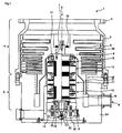
- Figure 1 is a view showing a general configuration of a turbo-molecular pump 1 in accordance with this embodiment.
- Figure 1 shows a cross section in the axis line direction of the turbo-molecular pump 1.
- This turbo-molecular pump is disposed, for example, in semiconductor manufacturing equipment, and is used when process gas is exhausted from a vacuum chamber.
- a casing 2 forming an outer shell of the turbo-molecular pump 1 has a substantially cylindrical shape, and constitutes a housing for the turbo-molecular pump 1 together with a threadedly grooved spacer 3 and a base 24 that are provided below the casing 2 (on the exhaust port 6 side).
- a structure for the turbo-molecular pump 1 to perform an exhaust function that is, a gas transfer mechanism is provided.
- This gas transfer mechanism is broadly divided into two sections: a rotating section supported rotatably and a fixed section fixed to the housing.
- an intake port 4 for introducing gas into the turbo-molecular pump 1 is formed in the end part of the casing 2. Also, on the end surface on the intake port 4 side of the casing 2, a flange part 5 projecting to the outer periphery side is formed.
- an exhaust port 6 is formed to exhaust gas from the turbo-molecular pump 1, that is, to discharge process gas etc. from the semiconductor manufacturing equipment.
- the rotating section is made up of a shaft 7, which is a rotating shaft, a rotor body 8 having a substantially inverse U-shaped cross section that is disposed on the shaft 7, rotor blades 9 provided on the rotor body 8, a cylindrical member 10 provided on the exhaust port 6 side (in the threadedly grooved pump section S), and the like.
- the rotor body 8 is fixed to the upper part of the shaft 7 by a bolt 23.
- the cylindrical member 10 is formed on the extension of the rotor body 8, and consists of a member having a cylindrical shape that is concentric with the rotation axis line of the rotor body 8.
- the rotor blades 9 are disposed at the outer periphery of the rotor body 8.
- the rotor blade 9 consists of a blade that extends radially from the shaft 7 in such a manner as to tilt through a predetermined angle from a plane perpendicular to the axis line of the shaft 7.
- a motor section 11 for rotating the shaft 7 at a high speed is provided.
- the motor section 11 is a DC brushless motor configured as described below.
- the motor section 11 is provided with a permanent magnet fixed to the periphery of the shaft 7. This permanent magnet is fixed so that, for example, the N poles and the S poles are arranged every 180 degrees around the shaft 7. Also, the motor section 11 is provided with an electromagnet disposed around the permanent magnet with a predetermined clearance being provided from the shaft 7. In this embodiment, six electromagnets are arranged every 60 degrees so as to be symmetrically opposed to the axis line of the shaft 7.
- the turbo-molecular pump is connected to a control unit, not shown, via a connector and a cable.
- the control unit changes over the exciting currents of the six electromagnets, by which a rotating magnetic field is generated around the permanent magnet fixed to the shaft 7. By allowing the permanent magnet to follow this rotating magnetic field, the shaft 7 is rotated.
- magnetic bearing sections 12 and 13 for pivotally supporting the shaft 7 in the radial direction are provided. Also, at the lower end (exhaust port side end) of the shaft 7, a magnetic bearing section 14 for pivotally supporting the shaft 7 in the axial direction is provided.
- These magnetic bearing sections 12 to 14 form what is called a five-axis control type magnetic bearing.
- the shaft 7 is supported in the radial direction (in the diameter direction of the shaft 7) in a noncontact manner by the magnetic bearing sections 12 and 13, and is supported in the thrust direction (in the axis direction of the shaft 7) in a noncontact manner by the magnetic bearing section 14.
- displacement sensors 15 to 17 for detecting the displacement of the shaft 7 are provided.
- the shaft 7 is formed of a material having a high magnetic permeability (iron etc.) so as to be attracted by the magnetic force of these electromagnets.
- the displacement sensor 15 detects the displacement in the radial direction of the shaft 7 by performing sampling at predetermined time intervals.
- control unit When the control unit, not shown, detects the displacement in the radial direction of the shaft 7 from a predetermined position by means of the displacement signal sent from the displacement sensor 15, the control unit operates so as to return the shaft 7 to the predetermined position by regulating the magnetic force of each of the electromagnets.
- the regulation of magnetic force of the electromagnet is accomplished by feedback controlling the exciting current of the electromagnet.
- the control unit feedback controls the magnetic bearing section 12 based on the signal of the displacement sensor 15, by which the shaft 7 is magnetically levitated in the radial direction in the magnetic bearing section 12 with a predetermined clearance being provided from the electromagnets, and is held in the air in a noncontact manner.
- the configuration and operation of the magnetic bearing section 13 are the same as those of the magnetic bearing section 12.
- the control unit feedback controls the magnetic bearing section 13 based on the signal of the displacement sensor 16, by which the shaft 7 is magnetically levitated in the radial direction in the magnetic bearing section 13, and is held in the air in a noncontact manner.
- the shaft 7 is held at a predetermined position in the radial direction by the operations of the magnetic bearing sections 12 and 13.
- the magnetic bearing section 14 has a disc-shaped metal disc 18 and electromagnets 19 and 20 to hold the shaft 7 in the thrust direction.
- the metal disc 18 is formed of a material having a high magnetic permeability such as iron, and is fixed to the shaft 7 perpendicularly in the center thereof.
- the electromagnets 19 and 20 are arranged so as to hold the metal disc 18 therebetween and are opposed to each other.
- the electromagnet 19 attracts the metal disc 18 upward by the magnetic force, and the electromagnet 20 attracts the metal disc 18 downward.
- the control unit properly regulates the magnetic forces applied to the metal disc 18 by the electromagnets 19 and 20 to magnetically levitate the shaft 7 in the thrust direction and hold the shaft 7 in the air in a noncontact manner.
- the displacement sensor 17 is disposed so as to be opposed to the lower end part of the shaft 7. This displacement sensor 17 detects the displacement in the thrust direction of the shaft 7 by sampling, and sends it to the control unit. The control unit detects the displacement in the thrust direction of the shaft 7 by means of the displacement detection signal received from the displacement sensor 17.
- the control unit When the shaft 7 moves in either thrust direction and is displaced from a predetermined position, the control unit feedback controls the exciting currents of the electromagnets 19 and 20 so as to correct this displacement to regulate the magnetic forces, and operates so as to return the shaft 7 to the predetermined position.
- the control unit carries out this feedback control continuously. Thereby, the shaft 7 is magnetically levitated at the predetermined position in the thrust direction, and is held.
- the shaft 7 is held in the radial direction by the magnetic bearing sections 12 and 13, and is held in the thrust direction by the magnetic bearing section 14, so that the shaft 7 rotates around the axis line thereof.
- protective bearings 21 and 22 are arranged on the upper side and the lower side of the shaft 7.
- the shaft 7 and the rotating section attached to the shaft 7 are pivotally supported by the magnetic bearing sections 12 and 13 in a noncontact manner during the time when they are rotated by the motor section 11.
- the protective bearings 21 and 22 are bearings for protecting the whole of the apparatus by pivotally supporting the rotating section in place of the magnetic bearing sections 12 and 13 in case of the occurrence of touching. Therefore, the protective bearings 21 and 22 are arranged so that the inner race is in the state of noncontact with the shaft 7.
- This fixed section is made up of stator blades 30 provided on the intake port 4 side (in the turbo-molecular pump section T), a threadedly grooved spacer 3, and the like. In the inner wall surface of the threadedly grooved spacer 3, a threaded groove part 40 is formed.
- the stator blade 30 has a blade extending from the inner peripheral surface of the housing toward the shaft so as to tilt through a predetermined angle from a plane perpendicular to the axis line of the shaft 7.
- stator blades 30 are formed in a plurality of stages in the axis line direction alternately with the rotor blades 9.
- stator blades 30 in the stages are separated from each other by spacer rings 31 each having a cylindrical shape shown in Figure 2 , and are held at predetermined positions.
- the spacer ring 31 is a ring-shaped member having a step part, and is formed of a metal such as aluminum, iron, or stainless steel.
- the interval between the adjacent stator blades 30 is set by the thickness of inner peripheral wall, that is, the length ( ⁇ ) in the axial direction.
- the inside diameter of the stator blade 30 in each stage is formed so as to be larger than the outside diameter of the rotor body 8 in the opposed portion so that the inner peripheral surface of the stator blade 30 does not come into contact with the outer peripheral surface of the rotor body 8.
- stator blade 30 in each stage is divided into two pieces in the circumferential direction to dispose the stator blade 30 between the rotor blades 9.
- the stator blade 30 is formed by cutting a semi-annular outer shape part and a blade part out of a halved thin plate formed of, for example, stainless steel or aluminum by etching or other methods and by bending the blade part through a predetermined angle by pressing.
- the stator blade 30 formed in this manner is assembled by being inserted between the rotor blades 9 from the outside.
- the stator blade 30 is held (fixed) between the rotor blades 9 in the state in which a part thereof on the outer periphery side is held in the circumferential direction by the spacer rings 31.
- the threaded groove part 40 is formed by a spiral groove formed along the surface opposed to the cylindrical member 10.
- the threaded groove part 40 is provided so as to face to the outer peripheral surface of the cylindrical member 10 with a predetermined clearance (gap) being provided.
- the direction of spiral groove formed in the threaded groove part 40 is the direction of the exhaust port 6 at the time when gas is transported in the rotation direction of the shaft 7 in the spiral groove.
- the depth of the spiral groove decreases toward the exhaust port 6, so that the gas transported in the spiral groove is compressed as it approaches the exhaust port 6.
- FIG. 3 is a view showing the details of the peripheral portions of the stator blades 30 in the turbo-molecular pump 1 in accordance with this embodiment.
- the rotor blades 9 are provided in nine stages. Between the rotor blades 9 provided in nine stages, the stator blades 30 (a total of eight stages) are disposed.
- spacer rings 31a to 31h are provided to fix the stator blades 30, which are provided in eight stages, in the state in which predetermined intervals are held.
- the rotor blade 9 has a different shape, for example, a different height (thickness) or a different tilt angle of blade according to the stage in which the rotor blade 9 is formed, so that the interval between the rotor blades 9 is also different according to the stage. Therefore, all of the shapes of the spacer rings 31a to 31h are not equal and different according to the shapes of the rotor blades 9 and the stator blades 30.
- Each of the spacer rings 31a to 31h is provided with a protruding part 34 and a step part 35 as shown in Figure 2 .
- the spacer rings 31a to 31h are positioned and fixed.
- a step part having a shape corresponding to the step part 35 is formed on the surface opposed to the intake port 4 in the outer peripheral part of the threadedly grooved spacer 3.
- a protruding part having a shape corresponding to the protruding part 34 is formed in a shoulder part (step part) near the intake port 4 in which the inside diameter of the casing 2 changes a little.
- turbo-molecular pump 1 in accordance with this embodiment is configured so that the outside diameters of the rotor blades 9 on the exhaust port 6 side are smaller than the outside diameters of the rotor blades 9 on the intake port 4 side.
- the configuration is such that the outside diameters of the rotor blades 9 down to the fifth stage from the intake port 4 side are equal, and the outside diameters of the rotor blades 9 from the sixth stage to the ninth stage from the intake port 4 side are smaller.
- the reason for this is that the centrifugal stress acting on the rotor blades 9 on the downstream side (the exhaust port 6 side) at the time when the shaft 7 rotates at a high speed is reduced.
- the outside diameter of the rotor blade 9 is also different according to the stage in which the rotor blade 9 is formed.
- the inside diameter of the spacer ring 31a to 31h opposed to the outer peripheral side surface of the rotor blade 9 differs according to the stage.
- the inside diameters of the spacer rings 31a to 31h in accordance with this embodiment are formed so as to decrease stepwise from the intake port 4 side toward the exhaust port 6 side.
- the spacer rings 31 of eight stages each provided for every stator blade 30 are named the spacer ring 31a, the spacer ring 31b, ... in the order from one arranged closest to the intake port 4 side, and one arranged closest to the exhaust port 6 side is named the spacer ring 31h.
- the spacer rings 31a to 31h are provided along the inner peripheral wall of the casing 2, and the spacer ring 31h disposed closest to the exhaust port 6 side is disposed along the surface opposed to the intake port 4 in the outer peripheral part of the threadedly grooved spacer 3.
- the casing 2 has a shape such that the inside diameter in the intake port 4 side end part is decreased a little, and is configured so that in a shoulder part (step part) in which the inside diameter of the casing 2 changes a little, the spacer ring 31a provided closest to the intake port 4 side is fixed.
- stator blades 30 and the spacer rings 31a to 31h stacked alternately are fixed in a state of being positioned by joining the casing 2 to the threadedly grooved spacer 3 by bolts 33.
- the spacer rings 31a to 31e opposed to the rotor blades 9 down to the fifth stage from the intake port 4 side, which are formed so that the outside diameters are equal, are formed into group A
- the spacer rings 31f to 31h opposed to the rotor blades 9 from the sixth stage to the eighth stage from the intake port 4 side, which are formed so that the outside diameters are small are formed into group B.
- the spacer rings 31a to 31h As in the case of the turbo-molecular pump 1 in accordance with this embodiment, of the spacer rings 31a to 31h, the spacer rings opposed to the rotor blades 9 having the largest outside diameter on the intake port 4 side are classified into group A, and, of the spacer rings 31a to 31h, the spacer rings having an inside diameter smaller than the largest outside diameter of the rotor blade 9 is classified into group B.
- the spacer rings 31a to 31h the spacer rings that can be inserted from the intake port 4 side without interference (contact) with the rotor blades 9 are classified into group A, and other spacer rings (interfering with the rotor blades 9) are classified into group B.
- the spacer rings 31a to 31h having been classified into group B by the above-described method are disposed in advance on the threadedly grooved spacer 3 in a stacked state.
- the shaft 7 of the rotating section is inserted along the bearing section of the base 24 from the upside on the drawing (the intake port 4 side), and the rotating section is fixed to the base 24, which is the fixed section, by using a nut 25 (refer to Figure 1 ).
- stator blade 30 having a halved shape is inserted between the rotor blades 9 from the outside in the radial direction through a clearance between the spacer ring 31h and the spacer ring 31g, and the inserted stator blade 30 is held by the spacer ring 31g and the spacer ring 31h, and is fixed.
- stator blade 30 is inserted between the rotor blades 9 through a clearance between the spacer ring 31g and the spacer ring 31f.
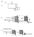
- the clearance d1 between the threadedly grooved spacer 3 and the spacer ring 31h, shown in Figure 4(b) , and the clearance d2 between the spacer ring 31h and the spacer ring 31g, shown in Figure 4(c) are configured so as to take a value larger than the height (thickness) of the inserted stator blade 30.
- the clearance between the spacer ring 31g and the spacer ring 31f is also configured so as to take a value larger than the height (thickness) h of the inserted stator blade 30.
- the clearance between the spacer ring 31h and the threadedly grooved spacer 3 and the clearance between the spacer rings 31f to 31h are movable (variable) clearances formed by raising (lifting up) the spacer rings 31f to 31h.
- the variable range of these clearances is restricted by the movable range of the spacer rings 31f to 31h.
- the outside diameters of the rotor blades 9 down to the fifth stage from the intake port 4 side are formed so as to be larger than the inside diameter of the spacer ring 31f. Therefore, the rotor blade 9 in the fifth stage from the intake port 4 side and the spacer ring 31f interfere (come into contact) with each other physically, so that the movable range of the spacer ring 31f is restricted by this portion.
- the movable range of the spacer rings 31f to 31h is restricted by a portion physically interfering (coming into contact) with the rotor blades 9, the adjacent spacer ring 31f to 31h, the inserted stator blades 30, and the like.
- the clearance through which the stator blade 30 is inserted that is, the clearance between the spacer ring 31h and the threadedly grooved spacer 3 and each of the clearances between the spacers 31f to 31h is set (designed) so as to be larger than the height (thickness) h of the inserted stator blade 30.
- the adjustment (regulation) of the clearance between the spacer ring 31h and the threadedly grooved spacer 3 and the clearances between the spacers 31f to 31h can be made by adjusting the interval at which the rotor blades 9 are formed, the height (thickness) h of the stator blade 30, the protruding part 34 on the spacer ring 31f to 31h shown in Figure 2 , the height (thickness) and shape of the spacer ring 31f to 31h, and the like.
- a level difference ⁇ is provided in the inner peripheral edge part of the upper surface (surface on the intake port 4 side) to secure (obtain) a distance necessary for preventing the interference (contact) with the rotor blade 9.
- This level difference ⁇ functions as an adjusting structure.
- the spacer ring 31 in the turbo-molecular pump 1 in accordance with this embodiment is formed by a ring-shaped body part 311 having a rectangular cross section, a step part 312 projecting from the end surface on the exhaust port 6 side of the body part 311 to the outer periphery, and a projecting part 313 projecting from the step part 312 to the exhaust port 6 side.
- the projecting part 313 of the adjacent spacer ring 31 and the outer peripheral wall of the body part 311 form a holding structure for holding the spacer ring 31 by engagement.
- the configuration is made such that the length obtained by adding the thickness (h) of the stator blade 30 to the length ( ⁇ ) from the end surface on the intake port 4 side of the body part 311 to the end surface on the intake port 4 side of the step part 312 is longer than the length (e) of the projecting part 313.
- stator blades 30 After the stator blades 30 have been inserted through the clearance between the spacer ring 31h and the threadedly grooved spacer 3 and the clearances between the spacer rings 31f to 31h, the stator blade 30 is inserted between the rotor blades 9 on the upper surface (the intake port 4 side surface) of the spacer ring 31f from the outside in the radial direction. Then, the spacer ring 31d is fitted from the intake port 4 side to fix the stator blade 30.
- stator blades 30 after the stator blades 30 have been disposed between the spacer rings 31f to 31h of group B, the stator blade 30 is further inserted from the outside in the radial direction, and the spacer rings 31a to 31d of group A are piled up one after another from the exhaust port 6 side while being fitted along the outside diameters of the rotor blades 9 from the intake port 4 side.
- a method of piling up (fitting) the spacer rings 31a to 31d of group A is the same as the conventional method.
- the casing 2 is installed so as to cover the spacer rings 31a to 31h, and the casing 2 is fixed to the threadedly grooved spacer 3.
- the casing 2 is fixed by using fastening members such as the bolts 33, for example, as shown in Figure 3 .
- the spacer rings 31a to 31h are fixed, and the stator blades 30 are fixedly disposed at proper positions between the rotor blades 9.
- the spacer rings 31a to 31h As described above, in this embodiment, of the spacer rings 31a to 31h, the spacer rings that cannot be fitted from the intake port 4 side because of the interference (contact) with the rotor blade 9 are disposed on the threadedly grooved spacer 3 in a stacked state before the rotating section (rotating body) is fixedly disposed on the fixed section (the base 24).
- the spacer rings 31f to 31h that cannot be fitted from the intake port 4 side because of the interference (contact) with the rotor blade 9 are disposed in advance on the threadedly grooved spacer 3, that is, on fixed member (fixed side) on which the spacer ring 31h is disposed.
- the turbo-molecular pump 1 in accordance with this embodiment has a construction such that the turbo-molecular pump 1 is not assembled so that the spacer rings 31f to 31h are fitted on the rotor blades 9 and are stacked, but assembled so that the rotor blades 9 (the rotor body 8) are fitted in the stacked spacer rings 31f to 31h.
- the turbo-molecular pump 1 since the turbo-molecular pump 1 in accordance with this embodiment has such a construction, the turbo-molecular pump 1 has a construction such that the outside diameters of the rotor blades 9 on the exhaust port 6 side are smaller than the outside diameters of the rotor blades 9 on the intake port 4 side.
- the spacer rings 31a to 31h that do not have a halved shape (that is, are integral) can be assembled easily.
- stator blades 30 can be assembled (piled up) without the use of spacer rings that are divided into two pieces in the circumferential direction.
- the assembling work can be performed one after another from the downside as in the conventional example, so that the assembling ability at the manufacturing time is not decreased.
- the strength can be improved as compared with the turbo-molecular pump using halved spacer rings.
- the strength against breaking torque at the time of abnormality can be improved.
- integral spacer rings 31a to 31h continuous in the circumferential direction have no possibility of the occurrence of troubles during processing (cutting) such as the deformation of cut surface, the distortion of external shape, and the shift of joint part (mating part), which may occur in the case of the halved spacer ring.
- the centrifugal stress acting on the rotor blade 9 on the downstream side (the exhaust port 6 side) when the shaft 7 rotates at a high speed can be reduced, so that the durability of the turbo-molecular pump 1 can be improved.
Landscapes
- Engineering & Computer Science (AREA)
- Mechanical Engineering (AREA)
- General Engineering & Computer Science (AREA)
- Non-Positive Displacement Air Blowers (AREA)
Claims (8)
- Pompe turbomoléculaire comprenant :un logement (2) ayant un port d'admission (4) et un port d'échappement (6) ;un corps rotatif (8) qui est renfermé dans le logement et possède des pales de rotor (9) d'une pluralité d'étages de pales de rotor qui sont formées de sorte que le diamètre extérieur de l'étage de pale de rotor du côté du port d'échappement soit plus petit que celui du côté du port d'admission ;un arbre rotatif (7) supportant de manière pivotante le corps rotatif ;un moteur pour tourner l'arbre rotatif ;des pales de stator (30) qui sont fixées au logement, étant agencées entre les pales de rotor, et donc chacune est divisée en au moins deux pièces ; etdes bagues d'entretoisement (31a-31h) ayant chacune une forme annulaire continue dans la direction circonférentielle qui sont disposées entre les pales de stator afin de retenir les pales de stator à des intervalles prédéterminés, et sont formées de telle sorte que le plus petit diamètre interne d'une bague d'entretoisement du côté du port d'échappement soit plus petit que le plus grand diamètre externe des pales de rotor ;caractérisée en ce quedans un état dans laquelle on postule que les pales de stator ne sont pas encore fixées au logement, une bague d'entretoisement (31h) du côté du port d'échappement peut être déplacée axialement entre une première position, qui bute sur le logement, et une seconde position, qui bute sur l'étage de pale de rotor ayant un diamètre externe plus grand que ledit diamètre interne le plus petit et situé plus près du port d'échappement ; dans laquelle :la distance de mouvement d'une bague d'entretoisement génère un espace libre, qui est plus grand que l'épaisseur (h) de la pale de stator.
- Pompe turbomoléculaire comprenant :un logement (2) ayant un port d'admission (4) et un port d'échappement (6) ;un corps rotatif (8) qui est renfermé dans le logement et possède des pales de rotor (9) d'une pluralité d'étages de pales de rotor qui sont formées de sorte que le diamètre extérieur de l'étage de pale de rotor du côté du port d'échappement soit plus petit que celui du côté du port d'admission ;un arbre rotatif (7) supportant de manière pivotante le corps rotatif ;un moteur pour tourner l'arbre rotatif ;des pales de stator (30) qui sont fixées au logement, étant agencées entre les pales de rotor, et donc chacune est divisée en au moins deux pièces ; etdes bagues d'entretoisement (31a-31h) ayant chacune une forme annulaire continue dans la direction circonférentielle qui sont disposées entre les pales de stator afin de retenir les pales de stator à des intervalles prédéterminés, et sont formées de telle sorte que le plus petit diamètre interne d'une bague d'entretoisement du côté du port d'échappement soit plus petit que le plus grand diamètre externe des pales de rotor ;caractérisée en ce quedans un état dans laquelle on postule que les pales de stator ne sont pas encore fixées au logement, la pluralité de bagues d'entretoisement (31f-31h) du côté du port d'échappement peuvent être empilées l'une sur l'autre et déplacées axialement comme une pile entre une première position, qui bute sur le logement, et une seconde position, qui bute sur l'étage de pale de rotor ayant un diamètre externe plus grand que ledit diamètre interne le plus petit et situé plus près du port d'échappement ; dans laquelle :la distance de mouvement de la pile (d1+ε) génère un espace libre (d1) qui est plus grand que l'épaisseur (h) de la pale de stator, etla distance entre deux bagues d'entretoisement adjacentes (31g, 31h) de la pile (d2+ε), quand une des deux bagues d'entretoisement adjacentes (31g) est dans sa position la plus éloignée du port d'échappement, alors que l'autre des deux bagues d'entretoisement adjacentes (31h) est dans sa position plus proche du port d'échappement, génère un espace libre (d2), qui est plus grand que l'épaisseur (h) de la pale de stator.
- Pompe turbomoléculaire selon les revendications 1 ou 2, caractérisée en ce que
la bague d'entretoisement (31a-31h) est formée par une partie de corps de forme annulaire (311) ayant une section transversale rectangulaire, une partie de gradin (312) se projetant depuis la surface d'extrémité du côté du port d'échappement de la partie de corps vers la périphérie externe, et une partie protubérante (313) se projetant depuis la partie de gradin vers le côté de port d'échappement,
la partie protubérante de la bague d'entretoisement adjacente et la paroi périphérique externe de la partie de corps forment une structure de retenue pour retenir la bague d'entretoisement par mise en prise, et
une longueur obtenue en ajoutant l'épaisseur (h) de la pale de stator à la longueur (γ) depuis la surface d'extrémité du côté du port d'admission de la partie de corps vers la surface d'extrémité du côté du port d'admission de la partie de gradin est plus grande que la longueur (E) de la partie protubérante. - Pompe turbomoléculaire selon la revendication 3, caractérisée en ce que la distance de mouvement (d1+ε) d'une bague d'entretoisement ou la pile de bagues d'entretoisement est plus grande que la somme de l'épaisseur de la pale de stator (h) et la longueur (E) de la partie protubérante.
- Pompe turbomoléculaire selon une quelconque des revendications précédentes, caractérisée en ce que une structure d'ajustement est prévue afin d'augmenter le déplacement axiale de la bague d'entretoisement.
- Pompe turbomoléculaire selon la revendication 5, caractérisée en ce que la structure d'ajustement est configurée par une différence de niveau (β) qui est formée sur l'intérieur et le côté du port d'admission de la bague d'entretoisement et dont le diamètre interne est plus grand que le diamètre externe de la pale de rotor.
- Procédé d'assemblage d'une pompe turbomoléculaire ayant :un logement (2) ayant un port d'admission (4) et un port d'échappement (6) ;un corps rotatif (8) qui est renfermé dans le logement et possède des pales de rotor (9) d'une pluralité d'étages de pales de rotor qui sont formées de sorte que le diamètre extérieur de l'étage de pale de rotor du côté du port d'échappement soit plus petit que celui du côté du port d'admission ;un arbre rotatif (7) supportant de manière pivotante le corps rotatif ;un moteur (11) pour tourner l'arbre rotatif ;des pales de stator (30) qui sont fixées au logement, étant agencées entre les pales de rotor, et donc chacune est divisée en au moins deux pièces ; etdes bagues d'entretoisement (31a-31h) ayant chacune une forme annulaire continue dans la direction circonférentielle qui sont disposées entre les pales de stator afin de retenir les pales de stator à des intervalles prédéterminés, et sont formées de telle sorte que le plus petit diamètre interne d'une bague d'entretoisement du côté du port d'échappement soit plus petit que le plus grand diamètre externe des pales de rotor ;caractérisé en ce qu'il comprend :une première étape de disposition seulement de la bague d'entretoisement ayant un diamètre interne plus petit que le diamètre externe le plus grand des pales de rotor sur le logement ou une partie fixe fixée au logement ;une seconde étape d'insertion du corps rotatif dans le logement ;une troisième étape de déplacement de la bague d'entretoisement disposée sur le logement ou la partie fixe fixée au logement dans la première étape vers le côté de port d'admission et de formation ainsi d'un espace libre entre la bague d'entretoisement et le logement ou la partie fixe fixée au logement ;une quatrième étape d'insertion d'une pale de stator entre le logement ou la partie fixe fixée au logement et un étage de pale de rotor depuis l'extérieur dans la direction radiale à travers ledit espace libre formé dans la troisième étape ; etune cinquième étape de déplacement de la bague d'entretoisement déplacée dans la troisième étape de manière à revenir vers le côté de port d'échappement et ainsi de fixation de la pale de stator insérée dans la quatrième étape.
- Procédé d'assemblage d'une pompe turbomoléculaire ayant :un logement (2) ayant un port d'admission (4) et un port d'échappement (6) ;un corps rotatif (8) qui est renfermé dans le logement et possède des pales de rotor (9) d'une pluralité d'étages de pales de rotor qui sont formées de sorte que le diamètre extérieur de l'étage de pale de rotor du côté du port d'échappement soit plus petit que celui du côté du port d'admission ;un arbre rotatif (7) supportant de manière pivotante le corps rotatif ;un moteur pour tourner l'arbre rotatif ;des pales de stator (30) qui sont fixées au logement, étant agencées entre les pales de rotor, et donc chacune est divisée en au moins deux pièces ; etdes bagues d'entretoisement (31a-31h) ayant chacune une forme annulaire continue dans la direction circonférentielle qui sont disposées entre les pales de stator afin de retenir les pales de stator à des intervalles prédéterminés, et sont formées de telle sorte que le plus petit diamètre interne d'une bague d'entretoisement du côté du port d'échappement soit plus petit que le plus grand diamètre externe des pales de rotor ;caractérisé en ce qu'il comprend :une première étape de disposition de la pluralité de bagues d'entretoisement (31f-31h) ayant un diamètre interne plus petit que le plus grand diamètre externe des pales de rotor dans une pile sur le logement ou une partie fixe fixée au logement ;une seconde étape d'insertion du corps rotatif dans le logement ;une troisième étape de déplacement de la pile de bagues d'entretoisement disposées sur le logement ou une partie fixe fixée au logement dans la première étape dans la direction du côté de port d'admission et ainsi de formation d'un premier espace libre (d1) entre la pile de bagues d'entretoisement et le logement ou la partie fixe fixée au logement ;une quatrième étape d'insertion d'une pale de stator entre les pales de rotor depuis l'extérieur dans la direction radiale à travers ledit premier espace libre (d1) formé dans la troisième étape ;une cinquième étape de déplacement de la bague d'entretoisement (31h) dans la pile, qui est située plus près du port d'échappement et a été déplacée dans la troisième étape, de manière à revenir vers le côté de port d'échappement et ainsi de fixation de la pale de rotor insérée dans la quatrième étape, le déplacement de la bague d'entretoisement (31h) en revenant au côté de port d'échappement formant un second espace libre (d2) entre la bague d'entretoisement et la bague d'entretoisement suivante (31g) dans la pile ;une sixième étape d'insertion d'une pale de stator entre les pales de rotor depuis l'extérieur dans la direction radiale à travers le second espace libre (d2) formé dans la cinquième étape ;une septième étape de déplacement de ladite bague d'entretoisement suivante (31g) dans la pile de manière à revenir vers le côté de port d'échappement et ainsi de fixation de la pale de stator insérée dans la sixième étape ;les étapes d'insertion de pale de stator et de déplacement de bague d'entretoisement étant répétées pour le reste des bagues d'entretoisement (31f) dans la pile, moyennant quoi, quand la dernière bague d'entretoisement (31f) dans la pile est déplacée de manière à revenir vers le côté de port d'échappement, un espace libre est créé entre la dernière bague d'entretoisement (31f) dans la pile et l'étage de pale de rotor, qui a un diamètre externe plus grande que ledit diamètre plus petit et qui est situé plus près du port d'échappement, espace libre à travers lequel une pale de stator est insérée.
Applications Claiming Priority (2)
| Application Number | Priority Date | Filing Date | Title |
|---|---|---|---|
| JP2005181389A JP4749054B2 (ja) | 2005-06-22 | 2005-06-22 | ターボ分子ポンプ、およびターボ分子ポンプの組み立て方法 |
| PCT/JP2006/312108 WO2006137333A1 (fr) | 2005-06-22 | 2006-06-16 | Pompe turbomoléculaire et procédé d’assemblage de pompe turbomoléculaire |
Publications (3)
| Publication Number | Publication Date |
|---|---|
| EP1900944A1 EP1900944A1 (fr) | 2008-03-19 |
| EP1900944A4 EP1900944A4 (fr) | 2010-03-31 |
| EP1900944B1 true EP1900944B1 (fr) | 2014-01-15 |
Family
ID=37570363
Family Applications (1)
| Application Number | Title | Priority Date | Filing Date |
|---|---|---|---|
| EP06766796.4A Active EP1900944B1 (fr) | 2005-06-22 | 2006-06-16 | Pompe turbomoléculaire et procédé d'assemblage de pompe turbomoléculaire |
Country Status (5)
| Country | Link |
|---|---|
| US (1) | US8366380B2 (fr) |
| EP (1) | EP1900944B1 (fr) |
| JP (1) | JP4749054B2 (fr) |
| KR (1) | KR101204633B1 (fr) |
| WO (1) | WO2006137333A1 (fr) |
Families Citing this family (14)
| Publication number | Priority date | Publication date | Assignee | Title |
|---|---|---|---|---|
| JP5062257B2 (ja) * | 2007-08-31 | 2012-10-31 | 株式会社島津製作所 | ターボ分子ポンプ |
| JP4519185B2 (ja) * | 2008-07-22 | 2010-08-04 | 株式会社大阪真空機器製作所 | ターボ分子ポンプ |
| JP2011027049A (ja) * | 2009-07-28 | 2011-02-10 | Shimadzu Corp | ターボ分子ポンプ |
| CN102536902A (zh) * | 2010-12-13 | 2012-07-04 | 致扬科技股份有限公司 | 涡轮分子泵的叶片结构改良 |
| JP6433812B2 (ja) | 2015-02-25 | 2018-12-05 | エドワーズ株式会社 | アダプタ及び真空ポンプ |
| JP6782141B2 (ja) | 2016-10-06 | 2020-11-11 | エドワーズ株式会社 | 真空ポンプ、ならびに真空ポンプに備わるらせん状板、スペーサおよび回転円筒体 |
| JP7088688B2 (ja) * | 2018-02-16 | 2022-06-21 | エドワーズ株式会社 | 真空ポンプと真空ポンプの制御装置 |
| JP7096006B2 (ja) * | 2018-02-16 | 2022-07-05 | エドワーズ株式会社 | 真空ポンプと真空ポンプの制御装置 |
| JP7668612B2 (ja) * | 2018-08-08 | 2025-04-25 | エドワーズ株式会社 | 真空ポンプ |
| CN110043485B (zh) * | 2019-05-16 | 2024-07-19 | 江苏博联硕焊接技术有限公司 | 一种涡轮分子泵转子及其扩散焊接方法 |
| JP7546412B2 (ja) | 2020-08-21 | 2024-09-06 | エドワーズ株式会社 | 真空ポンプ、固定翼、およびスペーサ |
| GB2604382A (en) * | 2021-03-04 | 2022-09-07 | Edwards S R O | Stator Assembly |
| JP7772520B2 (ja) * | 2021-07-26 | 2025-11-18 | エドワーズ株式会社 | 真空ポンプ |
| CN118836186B (zh) * | 2024-07-16 | 2025-10-21 | 中国联合重型燃气轮机技术有限公司 | 一种压气机静叶环周向限位组件及周向间隙的测量方法 |
Family Cites Families (7)
| Publication number | Priority date | Publication date | Assignee | Title |
|---|---|---|---|---|
| DE2554995A1 (de) * | 1975-12-06 | 1977-06-16 | Pfeiffer Vakuumtechnik | Turbomolekularpumpe |
| JPH0641798B2 (ja) * | 1986-07-29 | 1994-06-01 | 三菱重工業株式会社 | 気液二相流体分配器 |
| JPS6334393U (fr) * | 1986-08-20 | 1988-03-05 | ||
| JPH10246197A (ja) * | 1997-03-05 | 1998-09-14 | Ebara Corp | ターボ分子ポンプ |
| US6503050B2 (en) * | 2000-12-18 | 2003-01-07 | Applied Materials Inc. | Turbo-molecular pump having enhanced pumping capacity |
| EP1249613B1 (fr) * | 2001-03-15 | 2004-01-28 | VARIAN S.p.A. | Turbine-pompe avec un étage statorique intégré avec un anneau d'espacement |
| JP2003287463A (ja) * | 2002-03-28 | 2003-10-10 | Boc Edwards Technologies Ltd | 放射温度測定装置及び該放射温度測定装置を搭載したターボ分子ポンプ |
-
2005
- 2005-06-22 JP JP2005181389A patent/JP4749054B2/ja not_active Expired - Lifetime
-
2006
- 2006-06-16 EP EP06766796.4A patent/EP1900944B1/fr active Active
- 2006-06-16 KR KR1020077027228A patent/KR101204633B1/ko active Active
- 2006-06-16 WO PCT/JP2006/312108 patent/WO2006137333A1/fr not_active Ceased
- 2006-06-16 US US11/922,655 patent/US8366380B2/en active Active
Also Published As
| Publication number | Publication date |
|---|---|
| KR101204633B1 (ko) | 2012-11-23 |
| EP1900944A1 (fr) | 2008-03-19 |
| JP4749054B2 (ja) | 2011-08-17 |
| US8366380B2 (en) | 2013-02-05 |
| WO2006137333A1 (fr) | 2006-12-28 |
| JP2007002692A (ja) | 2007-01-11 |
| EP1900944A4 (fr) | 2010-03-31 |
| KR20080019591A (ko) | 2008-03-04 |
| US20090116959A1 (en) | 2009-05-07 |
Similar Documents
| Publication | Publication Date | Title |
|---|---|---|
| EP1900944B1 (fr) | Pompe turbomoléculaire et procédé d'assemblage de pompe turbomoléculaire | |
| EP1039137B1 (fr) | Pompe turbo-moléculair | |
| EP3415766B1 (fr) | Pompe à vide avec couvercle souple et rotor | |
| EP1413761A2 (fr) | Pompe turbomoléculaire et bride | |
| EP2108844A2 (fr) | Pompe à vide turbomoléculaire | |
| EP2644917A1 (fr) | Dispositif de commande de palier magnétique et pompe d'épuisement équipée de ce dispositif | |
| US20030077187A1 (en) | Molecular pump for forming a vacuum | |
| US8403652B2 (en) | Molecular pump and flange having shock absorbing member | |
| EP1795756B1 (fr) | Aube fixe d'une pompe turbomoléculaire | |
| JP6433812B2 (ja) | アダプタ及び真空ポンプ | |
| EP4006349A1 (fr) | Pompe à vide et rotor et palette rotative destinés à être utilisés dans une pompe à vide | |
| KR102739461B1 (ko) | 진공 펌프, 및 이 진공 펌프에 이용되는 원통부, 그리고 베이스부 | |
| US6607365B1 (en) | Vacuum pump and vacuum apparatus | |
| JP5276321B2 (ja) | ターボ分子ポンプ | |
| JP3038432B2 (ja) | 真空ポンプ及び真空装置 | |
| CN108626142B (zh) | 中心环及真空泵 | |
| EP1700039B1 (fr) | Dispositif de pompage a vide | |
| US6827550B2 (en) | Vacuum pump | |
| JP7502002B2 (ja) | 真空ポンプの製造方法、真空ポンプおよび真空ポンプ用のステータ | |
| JP2006090231A (ja) | ターボ分子ポンプ固定翼の製造方法および真空ポンプ | |
| WO2023237855A1 (fr) | Moyeu de palier magnétique et pompe à vide | |
| CN114026335A (zh) | 真空泵 |
Legal Events
| Date | Code | Title | Description |
|---|---|---|---|
| PUAI | Public reference made under article 153(3) epc to a published international application that has entered the european phase |
Free format text: ORIGINAL CODE: 0009012 |
|
| 17P | Request for examination filed |
Effective date: 20071224 |
|
| AK | Designated contracting states |
Kind code of ref document: A1 Designated state(s): DE FR GB |
|
| RBV | Designated contracting states (corrected) |
Designated state(s): DE FR GB |
|
| DAX | Request for extension of the european patent (deleted) | ||
| RBV | Designated contracting states (corrected) |
Designated state(s): DE FR GB |
|
| DAX | Request for extension of the european patent (deleted) | ||
| RAP1 | Party data changed (applicant data changed or rights of an application transferred) |
Owner name: EDWARDS JAPAN LIMITED |
|
| A4 | Supplementary search report drawn up and despatched |
Effective date: 20100303 |
|
| 17Q | First examination report despatched |
Effective date: 20100707 |
|
| GRAP | Despatch of communication of intention to grant a patent |
Free format text: ORIGINAL CODE: EPIDOSNIGR1 |
|
| RIC1 | Information provided on ipc code assigned before grant |
Ipc: F04D 29/64 20060101ALI20130812BHEP Ipc: F04D 19/04 20060101AFI20130812BHEP |
|
| INTG | Intention to grant announced |
Effective date: 20130919 |
|
| GRAS | Grant fee paid |
Free format text: ORIGINAL CODE: EPIDOSNIGR3 |
|
| GRAA | (expected) grant |
Free format text: ORIGINAL CODE: 0009210 |
|
| AK | Designated contracting states |
Kind code of ref document: B1 Designated state(s): DE FR GB |
|
| REG | Reference to a national code |
Ref country code: GB Ref legal event code: FG4D |
|
| REG | Reference to a national code |
Ref country code: DE Ref legal event code: R096 Ref document number: 602006040084 Country of ref document: DE Effective date: 20140227 |
|
| REG | Reference to a national code |
Ref country code: DE Ref legal event code: R097 Ref document number: 602006040084 Country of ref document: DE |
|
| PLBE | No opposition filed within time limit |
Free format text: ORIGINAL CODE: 0009261 |
|
| STAA | Information on the status of an ep patent application or granted ep patent |
Free format text: STATUS: NO OPPOSITION FILED WITHIN TIME LIMIT |
|
| 26N | No opposition filed |
Effective date: 20141016 |
|
| REG | Reference to a national code |
Ref country code: DE Ref legal event code: R097 Ref document number: 602006040084 Country of ref document: DE Effective date: 20141016 |
|
| REG | Reference to a national code |
Ref country code: FR Ref legal event code: PLFP Year of fee payment: 11 |
|
| REG | Reference to a national code |
Ref country code: FR Ref legal event code: PLFP Year of fee payment: 12 |
|
| REG | Reference to a national code |
Ref country code: FR Ref legal event code: PLFP Year of fee payment: 13 |
|
| P01 | Opt-out of the competence of the unified patent court (upc) registered |
Effective date: 20230503 |
|
| PGFP | Annual fee paid to national office [announced via postgrant information from national office to epo] |
Ref country code: DE Payment date: 20250627 Year of fee payment: 20 |
|
| PGFP | Annual fee paid to national office [announced via postgrant information from national office to epo] |
Ref country code: GB Payment date: 20250627 Year of fee payment: 20 |
|
| PGFP | Annual fee paid to national office [announced via postgrant information from national office to epo] |
Ref country code: FR Payment date: 20250625 Year of fee payment: 20 |