EP1900955A1 - Anneau synchrone - Google Patents
Anneau synchrone Download PDFInfo
- Publication number
- EP1900955A1 EP1900955A1 EP07112152A EP07112152A EP1900955A1 EP 1900955 A1 EP1900955 A1 EP 1900955A1 EP 07112152 A EP07112152 A EP 07112152A EP 07112152 A EP07112152 A EP 07112152A EP 1900955 A1 EP1900955 A1 EP 1900955A1
- Authority
- EP
- European Patent Office
- Prior art keywords
- synchronizer ring
- friction
- hub
- annular body
- synchronizer
- Prior art date
- Legal status (The legal status is an assumption and is not a legal conclusion. Google has not performed a legal analysis and makes no representation as to the accuracy of the status listed.)
- Granted
Links
Images


Classifications
-
- F—MECHANICAL ENGINEERING; LIGHTING; HEATING; WEAPONS; BLASTING
- F16—ENGINEERING ELEMENTS AND UNITS; GENERAL MEASURES FOR PRODUCING AND MAINTAINING EFFECTIVE FUNCTIONING OF MACHINES OR INSTALLATIONS; THERMAL INSULATION IN GENERAL
- F16D—COUPLINGS FOR TRANSMITTING ROTATION; CLUTCHES; BRAKES
- F16D23/00—Details of mechanically-actuated clutches not specific for one distinct type
- F16D23/02—Arrangements for synchronisation, also for power-operated clutches
- F16D23/025—Synchro rings
Definitions
- the invention relates to a synchronizer ring for a synchronizer of a shiftable change-speed gearbox and a manual transmission for a vehicle according to the preamble of the independent claims 1 and 10.
- Synchronizer rings serve in a mechanical shiftable change-speed gearbox, e.g. in vehicle transmissions to match the occurring during a gear change relative speeds between gear and gear shaft to each other.
- the synchronization is achieved by friction between the corresponding friction partner.
- the mode of operation of such transmissions and the course of the synchronization process are known per se and need not be explained in detail to the person skilled in the art.
- synchronizer rings which are usually made of a metal or a metal alloy, such as brass or steel, with a friction layer.
- friction layers There are very different types of friction layers in use, eg thermal spray coatings of molybdenum, carbon friction coatings or friction coatings of other materials,
- a carrier for a cone-shaped synchronizer ring which has a three-divided outer ring gear and in a cylindrical cavity of a Synchronringnabe, which is often referred to as a synchronizer ring body is arranged and via stops, which are formed as lobes with the synchronizer ring hub substantially rotationally fixed is anchored.
- Substantially non-rotatable means in the context of this application that, except for small angular deflections in the circumferential direction of the synchronizer ring is rotatably connected to the synchronizer ring hub.
- the DE 198 53 856 A1 describes a development of the above-described synchronizer ring, wherein the synchronizer ring of DE 198 53 856 A1 characterized in that its width is determined substantially only by the required width of its friction surface. This is achieved by making a stop that functionally matches the cloth DE 35 19811 A1 correspond to, is arranged on or near an end portion of the annular body with a smaller cone diameter, and the contour of the stop protrudes in the radial direction over the contour of the outer circumferential surface of the annular body.
- the object of the invention is therefore to provide an improved synchronizer ring, which is better guided in the synchronizer ring hub and in which no uncontrolled relative movements between synchronizer ring and Synchronringnabe during and / or outside the synchronization process occur in the operating state.
- the invention thus relates to a synchronizer ring for a synchronizer of a switchable change-speed gearbox, comprising a conical annular body with an inner friction surface and an outer mounting surface, which define the annular body in a radial circumferential direction in each case, and extend at a predeterminable friction angle conically around an axial synchronizer ring axis of the synchronizer ring.
- the annular body is limited in the axial direction at a largest cone diameter by a substantially perpendicular to the synchronizer ring axis extending gear surface with gear, and limited to a smallest cone diameter by a hub surface.
- an anti-twist device is provided, which is integrally connected to the annular body and extends from the toothed wheel surface of the annular body in the direction of the hub surface.
- a guide element is provided for guiding the mounting surface on an inner surface of the cylindrical cavity of the synchronizing ring hub on the annular body in a predeterminable area between the toothed wheel surface and the hub surface.
- a guide element is provided for supporting or centering and guiding the mounting surface on an inner surface of the cylindrical cavity of the synchronizing ring hub on the annular body in a predeterminable area between the gear surface and the hub surface, preferably in the form of several bulges, which are distributed over the mounting surface in the circumferential direction, is provided.
- a synchronizer ring according to the invention is at the same time outstandingly secured against rotation relative to the Synchronringnabe by Vermosschen, and is also reliable, especially with respect to the radial direction in the cylindrical cavity guided and centered in the synchronizer ring hub.
- a synchronizer ring according to the invention due to its conical outer shape, which cooperates with a cylindrical inner contact surface in the cylindrical cavity of the synchronizing ring hub, no longer tends, like the conical synchronizing rings known from the prior art, to uncontrolled movements, e.g. to small radial deflections or tilting movements, e.g. can express in unpleasant vibrations.
- the reliability and accuracy of the synchronization process by using a synchronizer ring according to the invention is significantly positively influenced, which can be a reduction in the switching times, reduces the wear on the friction surface and the entire synchronizer ring as such and thus contributes to longer repair and maintenance intervals, quite apart of the fact that the switching and driving comfort of a motor vehicle is significantly increased by the excellent guidance of the synchronizing ring according to the invention in the cavity of the synchronizing ring hub.
- These positive effects have the stronger effect, the more power or torque must be switched by a corresponding gear.
- the gear surface is interrupted by a recess, in particular by one, or two, or three, or more than three recesses, and / or the rotation is connected in the recess with the annular body.
- the rotation can be formed as a securing tab, which extends on the side facing away from the synchronizer ring axis of the ring body substantially rectified to the mounting surface.
- the securing tab may be a securing tab with a pocket-shaped recess, whereby in an individual case an improved anchoring of the synchronizing ring in the synchronizing ring hub can be achieved.
- the number of guide elements which may be provided on a synchronizer ring according to the invention, is preferably between two and nine guide elements, in particular three guide elements, more preferably six guide elements are provided, and / or two guide elements in the circumferential direction at substantially the same distance and / or in each case two guide elements are arranged between two anti-rotation, whereby with minimal design effort, a maximum amount of radial guidance is guaranteed.
- the guide element is in the form of a bulge of the annular body formed on the mounting surface, which bulge extends radially away from the synchronizer ring axis outwards.
- a wear-reducing and / or a friction-optimized friction means in particular a friction coating, in particular a molybdenum coating and / or a friction lining, in particular a carbon friction lining and / or another friction means are provided on or on the friction surface.
- the synchronizer ring is made of a thermoformable sheet metal formed part and / or made of a steel, preferably made of C55, C80 or C80M steel, in particular C35 or C45 steel.
- the invention further relates to a manual transmission for a vehicle, in particular for a passenger car, a van or a truck with a synchronizer ring according to one of the preceding claims.
- FIG. 1 shows in a schematic representation in section an embodiment of an inventive synchronizer ring, which is referred to in the following as a whole by the reference numeral 1.
- like reference numerals in the various figures indicate technically equivalent features or relate to features with technically equivalent function.
- the synchronizer ring 1 of Fig. 1 comprises a conical annular body 3 with an inner friction surface 4 with carbon friction lining 41 and an outer mounting surface 5, which limit the annular body 3 in a radial circumferential direction in a conventional manner in each case.
- the outer mounting surface 5 and the inner friction surface 4 extend substantially parallel to each other at a predeterminable friction angle ⁇ , which is not visible in Fig. 1, conical about an axial synchronizer ring axis 6 of the synchronizer ring. 1
- the annular body 3 is limited in the axial direction at a largest cone diameter d1 by a substantially perpendicular to the synchronizer ring axis 6 extending gear surface 7 with gear 71, and limited to a smallest cone diameter d2 by a hub surface 8.
- a rotation 11 is provided, which is integrally connected to the ring body 3 and from the gear surface 7 of the ring body 3 in the direction of the hub surface 8 extends, a construction, as it is already known in principle from the prior art.
- a securing tab 111 which may be formed in the direction of the mounting surface 5, for example, in the manufacture of the synchronizer ring 1 by bending over a portion of the annular body 3 initially radially outwardly.
- the securing tab 111 is designed and arranged with respect to the installation surface such that the securing tab 111 can be anchored in the installed state in a corresponding recess 101 of the synchronizing ring hub 10.
- a guide member 12 is provided, which is enormously important in practice Embodiment of FIG. 1 in the form of a lifting 12 of the annular body 3 is formed on the mounting surface 5, wherein the bulge 12 extends radially outwardly away from the synchronizer ring axis 6.
- the bulges 12 according to the invention center and guide the synchronizer ring 1 reliably and reliably in the cylindrical cavity 9 provided in the synchronizer ring hub 10 for receiving the mounting surface 5.
- FIG. 2 is a side view of a synchronizer ring 1 according to FIG. 1 in the installed state shown schematically. The cut is just along the arrow A according to FIG. 3 chosen so that the securing tab 111 is not visible.
- the synchronizer ring 1 is centered by the inventive guide elements 12, which are provided as bulges 12, with the mounting surface 5 in the cavity 9 of the synchronizer ring hub 10.
- the gear surface 7 with gear 71 is located in a conventional manner outside the synchronizer hub 10, so that the gear 71 can rotate with a further, not shown in FIG. 2 gear of a likewise not shown shiftable change-speed gearbox.
- FIG. 3 again shows the synchronizer ring of FIG. 1 from a direction B according to FIG. 2 in a section along and at the point C, as indicated by the arrow C in FIG. 2.
- a securing tab 111 is anchored in the recess 101 of the synchronizer ring hub 10.
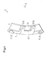
- FIG. 4 Another special embodiment of the present invention is shown schematically in FIG. 4, wherein the anti-rotation device 11 is a securing lug 111, which is designed as a securing lug 1110 with pocket-shaped recesses, so that these are anchored in a corresponding recess of another synchronizing ring hub 10 can, wherein the recesses for anchoring the securing tabs 1110 of the other synchronizer ring hub 10 then, for example are formed in two parts with a central web, whereby in certain cases a better fixation of the synchronizer ring 1 on the synchronizer hub 10 is possible.
- the anti-rotation device 11 is a securing lug 111, which is designed as a securing lug 1110 with pocket-shaped recesses, so that these are anchored in a corresponding recess of another synchronizing ring hub 10 can, wherein the recesses for anchoring the securing tabs 1110 of the other synchronizer ring hub 10 then, for example are formed in
Landscapes
- Engineering & Computer Science (AREA)
- General Engineering & Computer Science (AREA)
- Mechanical Engineering (AREA)
- Mechanical Operated Clutches (AREA)
Priority Applications (1)
| Application Number | Priority Date | Filing Date | Title |
|---|---|---|---|
| EP07112152A EP1900955B1 (fr) | 2006-09-15 | 2007-07-10 | Anneau synchrone |
Applications Claiming Priority (2)
| Application Number | Priority Date | Filing Date | Title |
|---|---|---|---|
| EP06120716 | 2006-09-15 | ||
| EP07112152A EP1900955B1 (fr) | 2006-09-15 | 2007-07-10 | Anneau synchrone |
Publications (2)
| Publication Number | Publication Date |
|---|---|
| EP1900955A1 true EP1900955A1 (fr) | 2008-03-19 |
| EP1900955B1 EP1900955B1 (fr) | 2010-11-10 |
Family
ID=39079466
Family Applications (1)
| Application Number | Title | Priority Date | Filing Date |
|---|---|---|---|
| EP07112152A Ceased EP1900955B1 (fr) | 2006-09-15 | 2007-07-10 | Anneau synchrone |
Country Status (1)
| Country | Link |
|---|---|
| EP (1) | EP1900955B1 (fr) |
Cited By (2)
| Publication number | Priority date | Publication date | Assignee | Title |
|---|---|---|---|---|
| EP2136098A1 (fr) | 2008-06-18 | 2009-12-23 | Sulzer Friction Systems (Germany) GmbH | Bague de synchronisation ainsi que boîte manuelle à engrenages pour un véhicule |
| FR2938031A1 (fr) * | 2008-11-04 | 2010-05-07 | Renault Sas | Absorption des oscillations de couple pour dispositif de couplage d'un arbre de boite de vitesses avec un pignon fou monte sur cet arbre |
Citations (4)
| Publication number | Priority date | Publication date | Assignee | Title |
|---|---|---|---|---|
| DE3519811A1 (de) * | 1985-06-03 | 1986-12-04 | Borg-Warner GmbH, 6900 Heidelberg | Traeger fuer einen synchronisierring |
| US5626214A (en) * | 1994-12-21 | 1997-05-06 | Saab Automobile Aktiebolag | Arrangement for preventing rattling in a synchronized gearbox |
| DE19719618A1 (de) * | 1997-05-09 | 1998-11-12 | Schaeffler Waelzlager Ohg | Synchronring, der aus mehreren Einzelteilen zusammengefügt ist |
| DE19922325C1 (de) * | 1999-05-14 | 2000-07-13 | Daimler Chrysler Ag | Schaltmuffenträger |
Family Cites Families (1)
| Publication number | Priority date | Publication date | Assignee | Title |
|---|---|---|---|---|
| AT401555B (de) * | 1994-12-13 | 1996-10-25 | Hoerbiger & Co | Synchronisierungseinrichtung für schaltgetriebe |
-
2007
- 2007-07-10 EP EP07112152A patent/EP1900955B1/fr not_active Ceased
Patent Citations (4)
| Publication number | Priority date | Publication date | Assignee | Title |
|---|---|---|---|---|
| DE3519811A1 (de) * | 1985-06-03 | 1986-12-04 | Borg-Warner GmbH, 6900 Heidelberg | Traeger fuer einen synchronisierring |
| US5626214A (en) * | 1994-12-21 | 1997-05-06 | Saab Automobile Aktiebolag | Arrangement for preventing rattling in a synchronized gearbox |
| DE19719618A1 (de) * | 1997-05-09 | 1998-11-12 | Schaeffler Waelzlager Ohg | Synchronring, der aus mehreren Einzelteilen zusammengefügt ist |
| DE19922325C1 (de) * | 1999-05-14 | 2000-07-13 | Daimler Chrysler Ag | Schaltmuffenträger |
Cited By (5)
| Publication number | Priority date | Publication date | Assignee | Title |
|---|---|---|---|---|
| EP2136098A1 (fr) | 2008-06-18 | 2009-12-23 | Sulzer Friction Systems (Germany) GmbH | Bague de synchronisation ainsi que boîte manuelle à engrenages pour un véhicule |
| JP2010002052A (ja) * | 2008-06-18 | 2010-01-07 | Sulzer Friction Systems (Germany) Gmbh | 車両用の同期リング及びギヤ・チェンジ変速機 |
| US9133894B2 (en) | 2008-06-18 | 2015-09-15 | OERLIKON FRICTION SYSTEMS (GERMANY) GmbH | Synchronizing ring and gear changing transmission for a vehicle |
| FR2938031A1 (fr) * | 2008-11-04 | 2010-05-07 | Renault Sas | Absorption des oscillations de couple pour dispositif de couplage d'un arbre de boite de vitesses avec un pignon fou monte sur cet arbre |
| EP2184502A1 (fr) * | 2008-11-04 | 2010-05-12 | Renault S.A.S. | Absorption des oscillations de couple pour dispositif de couplage d'un arbre de boîte de vitesses avec un pignon fou monté sur cet arbre |
Also Published As
| Publication number | Publication date |
|---|---|
| EP1900955B1 (fr) | 2010-11-10 |
Similar Documents
| Publication | Publication Date | Title |
|---|---|---|
| EP2136098B1 (fr) | Bague de synchronisation ainsi que boîte manuelle à engrenages pour un véhicule | |
| EP2894363B1 (fr) | Anneau de friction, anneau de synchronisation, appareil de synchronisation, ainsi que boîte manuelle à engrenages pour un véhicule | |
| DE102008023031B4 (de) | Blech-Synchronring | |
| EP2677187B1 (fr) | Anneau de friction, appareil de synchronisation, ainsi que boîte manuelle à engrenages pour un véhicule | |
| EP2739874B1 (fr) | Cylindre récepteur | |
| EP2677188B1 (fr) | Anneau de synchronisation | |
| EP3112716B1 (fr) | Composant d'unitè de synchronisation d'une boîte manuelle à engrenage | |
| EP3347612B1 (fr) | Élément de pression d'une boîte de vitesses de véhicule et unité de syncrhonisation | |
| EP2980427A1 (fr) | Dispositif de palier lisse | |
| DE102016216496A1 (de) | Gewindetrieb | |
| DE102011015836A1 (de) | Blech-Synchronring sowie Verfahren zur Herstellung eines Blech-Synchronrings | |
| EP1175569B1 (fr) | Element de synchronisation composite avec butee | |
| WO2008025585A1 (fr) | Dispositif de synchronisation à éléments en acier et en laiton en liaison avec un revêtement de friction | |
| DE102019120225A1 (de) | Ventil und Vorrichtung zur Regelung von Drücken eines Strömungsmittels mit dem Ventil sowie Vorrichtung zur Sicherung des Ventils in dem Getriebebauteil | |
| EP1900955B1 (fr) | Anneau synchrone | |
| EP2630385B1 (fr) | Frein de stationnement | |
| DE102006018284A1 (de) | Synchronisiereinrichtung | |
| EP1936223B1 (fr) | Anneau de synchronisation | |
| DE102012220652A1 (de) | Nockenwelle | |
| EP1711728B1 (fr) | Fourchette de boite de vitesses | |
| EP3153732B1 (fr) | Anneau de friction pour une unité de synchronisation | |
| EP1887240A1 (fr) | Bague de synchronisation | |
| DE102010025332A1 (de) | Spindelhubgetriebe mit Verdrehsicherung | |
| WO2008067795A2 (fr) | Bille de roulement à billes, son procédé de réalisation, et cage pour roulement à billes comprenant de telles billes | |
| DE102014202506A1 (de) | Kupplungskörper |
Legal Events
| Date | Code | Title | Description |
|---|---|---|---|
| PUAI | Public reference made under article 153(3) epc to a published international application that has entered the european phase |
Free format text: ORIGINAL CODE: 0009012 |
|
| AK | Designated contracting states |
Kind code of ref document: A1 Designated state(s): AT BE BG CH CY CZ DE DK EE ES FI FR GB GR HU IE IS IT LI LT LU LV MC MT NL PL PT RO SE SI SK TR |
|
| AX | Request for extension of the european patent |
Extension state: AL BA HR MK YU |
|
| 17P | Request for examination filed |
Effective date: 20080401 |
|
| 17Q | First examination report despatched |
Effective date: 20080508 |
|
| AKX | Designation fees paid |
Designated state(s): DE FR GB IT |
|
| GRAP | Despatch of communication of intention to grant a patent |
Free format text: ORIGINAL CODE: EPIDOSNIGR1 |
|
| GRAC | Information related to communication of intention to grant a patent modified |
Free format text: ORIGINAL CODE: EPIDOSCIGR1 |
|
| RAP1 | Party data changed (applicant data changed or rights of an application transferred) |
Owner name: SULZER FRICTION SYSTEMS (GERMANY) GMBH |
|
| GRAS | Grant fee paid |
Free format text: ORIGINAL CODE: EPIDOSNIGR3 |
|
| GRAA | (expected) grant |
Free format text: ORIGINAL CODE: 0009210 |
|
| AK | Designated contracting states |
Kind code of ref document: B1 Designated state(s): DE FR GB IT |
|
| REG | Reference to a national code |
Ref country code: GB Ref legal event code: FG4D Free format text: NOT ENGLISH |
|
| REF | Corresponds to: |
Ref document number: 502007005600 Country of ref document: DE Date of ref document: 20101223 Kind code of ref document: P |
|
| PLBE | No opposition filed within time limit |
Free format text: ORIGINAL CODE: 0009261 |
|
| STAA | Information on the status of an ep patent application or granted ep patent |
Free format text: STATUS: NO OPPOSITION FILED WITHIN TIME LIMIT |
|
| 26N | No opposition filed |
Effective date: 20110811 |
|
| REG | Reference to a national code |
Ref country code: DE Ref legal event code: R097 Ref document number: 502007005600 Country of ref document: DE Effective date: 20110811 |
|
| REG | Reference to a national code |
Ref country code: FR Ref legal event code: PLFP Year of fee payment: 10 |
|
| REG | Reference to a national code |
Ref country code: FR Ref legal event code: PLFP Year of fee payment: 11 |
|
| REG | Reference to a national code |
Ref country code: FR Ref legal event code: PLFP Year of fee payment: 12 |
|
| PGFP | Annual fee paid to national office [announced via postgrant information from national office to epo] |
Ref country code: IT Payment date: 20230721 Year of fee payment: 17 Ref country code: GB Payment date: 20230725 Year of fee payment: 17 |
|
| PGFP | Annual fee paid to national office [announced via postgrant information from national office to epo] |
Ref country code: FR Payment date: 20230725 Year of fee payment: 17 Ref country code: DE Payment date: 20230726 Year of fee payment: 17 |
|
| REG | Reference to a national code |
Ref country code: DE Ref legal event code: R119 Ref document number: 502007005600 Country of ref document: DE |
|
| GBPC | Gb: european patent ceased through non-payment of renewal fee |
Effective date: 20240710 |
|
| PG25 | Lapsed in a contracting state [announced via postgrant information from national office to epo] |
Ref country code: DE Free format text: LAPSE BECAUSE OF NON-PAYMENT OF DUE FEES Effective date: 20250201 |
|
| PG25 | Lapsed in a contracting state [announced via postgrant information from national office to epo] |
Ref country code: FR Free format text: LAPSE BECAUSE OF NON-PAYMENT OF DUE FEES Effective date: 20240731 |
|
| PG25 | Lapsed in a contracting state [announced via postgrant information from national office to epo] |
Ref country code: GB Free format text: LAPSE BECAUSE OF NON-PAYMENT OF DUE FEES Effective date: 20240710 |
|
| PG25 | Lapsed in a contracting state [announced via postgrant information from national office to epo] |
Ref country code: IT Free format text: LAPSE BECAUSE OF NON-PAYMENT OF DUE FEES Effective date: 20240710 |