EP1900968A2 - Installation de chauffage, en particulier installation de chauffage à induction - Google Patents
Installation de chauffage, en particulier installation de chauffage à induction Download PDFInfo
- Publication number
- EP1900968A2 EP1900968A2 EP07015178A EP07015178A EP1900968A2 EP 1900968 A2 EP1900968 A2 EP 1900968A2 EP 07015178 A EP07015178 A EP 07015178A EP 07015178 A EP07015178 A EP 07015178A EP 1900968 A2 EP1900968 A2 EP 1900968A2
- Authority
- EP
- European Patent Office
- Prior art keywords
- chain
- heating
- workpieces
- ceramic
- transport
- Prior art date
- Legal status (The legal status is an assumption and is not a legal conclusion. Google has not performed a legal analysis and makes no representation as to the accuracy of the status listed.)
- Withdrawn
Links
Images

Classifications
-
- F—MECHANICAL ENGINEERING; LIGHTING; HEATING; WEAPONS; BLASTING
- F16—ENGINEERING ELEMENTS AND UNITS; GENERAL MEASURES FOR PRODUCING AND MAINTAINING EFFECTIVE FUNCTIONING OF MACHINES OR INSTALLATIONS; THERMAL INSULATION IN GENERAL
- F16G—BELTS, CABLES, OR ROPES, PREDOMINANTLY USED FOR DRIVING PURPOSES; CHAINS; FITTINGS PREDOMINANTLY USED THEREFOR
- F16G13/00—Chains
- F16G13/18—Chains having special overall characteristics
-
- H—ELECTRICITY
- H05—ELECTRIC TECHNIQUES NOT OTHERWISE PROVIDED FOR
- H05B—ELECTRIC HEATING; ELECTRIC LIGHT SOURCES NOT OTHERWISE PROVIDED FOR; CIRCUIT ARRANGEMENTS FOR ELECTRIC LIGHT SOURCES, IN GENERAL
- H05B6/00—Heating by electric, magnetic or electromagnetic fields
- H05B6/02—Induction heating
- H05B6/10—Induction heating apparatus, other than furnaces, for specific applications
- H05B6/101—Induction heating apparatus, other than furnaces, for specific applications for local heating of metal pieces
- H05B6/103—Induction heating apparatus, other than furnaces, for specific applications for local heating of metal pieces multiple metal pieces successively being moved close to the inductor
Definitions
- the invention relates to a heating system, in particular an induction heating system, for heating workpieces.
- the furnace When shutting down a piercing furnace, the furnace must be emptied to avoid cooling and leaving the workpieces in the furnace. However, since a new workpiece must be inserted to feed out a workpiece, phantom pieces must be inserted into the feed of the furnace. However, phantom pieces assume that a system operator inserts these parts. This leads to an additional operating effort.
- the injector is provided with a feed unit and can thus deliver the parts in time. In this case, however, space for the discharge unit is required in addition to the space for the heating furnace. This means that the system reaches at least twice the length. Both are usually undesirable or at least hindering from operational.
- a disadvantage of such ovens is further that due to the separation of the parts and the necessary return stroke of the injector very quickly a minimum cycle time is reached, which can not be exceeded .
- flat and relatively light workpieces can not be heated with a puncture oven. There is a risk here that a workpiece pushes under or over another workpiece and the workpieces become wedged in the furnace. The promotion of the workpieces fails and the workpieces must be removed individually manually. Often then additionally the oven must be switched off.
- transport chains made of temperature-resistant steel for the promotion of workpieces by a heating system are known.
- an endless chain runs through the furnace, on which the workpieces to be heated are located.
- Such chains can be used only in a heating with gas or oil or resistance heating .
- the known transport chains can not be used.
- coils or inductors generate strong alternating magnetic fields which induce eddy currents in conductive materials. Due to the ohmic resistance these currents are converted into heat.
- this effect not only occurs as intended in the workpieces located in the oven, but also a transport chain is heated to a high degree. As a result, the chain can reach a higher temperature than the workpieces themselves.
- the chain links can withstand the high temperatures, but there remains a further problem: eddy currents generally do not form exclusively in the chain links. On the contrary, current flows also occur between the chain links and with other parts of the system, for example a sprocket, which flow, for example, via the connectors between the chain links. At very high current densities arcs may also occur between adjacent parts. This leads to a welding of the chain links and makes the chain no longer usable within a few minutes.
- the present invention is therefore based on the object, a heating system of the type mentioned in such a way and further, that the most effective and flexible transport of workpieces can be achieved by the heating system.
- the heating system in question is characterized in that a transport chain is provided, by means of which the workpiece to be heated can be transported by the heating system, and that the transport chain is made of a ceramic material.
- a transport chain can nevertheless be used if welding of the chain links with one another can be prevented.
- the current flow between the chain links must be effectively prevented.
- a transport chain for the transport of the workpieces is used by the heating system, which is made of a ceramic material according to the invention. Since ceramics are generally non-conductors, there are no eddy currents in the chain. Only dielectric losses can occur, which, however, lead to comparatively little warming.
- the use of a ceramic chain in an induction heating system eliminates the need for a jammer. This makes laying the parts easy and quick to carry out.
- the workpieces can be placed on the chain by a continuous feed process. It can thus also workpieces heat inductively, which could not be driven by an oven so far by their geometry, for example in conical cylinders or flat parts, with the help of conventional transport options. An increase of parts within the furnace by the column pressure is avoided and also workpieces with small diameters and short lengths can be driven.
- the throughput speed of the workpieces through the oven is limited only by the desired temperature and the maximum or desired oven length.
- a limitation by the mechanical movement of a pusher is not given anymore.
- the emptying of the system is done in the simplest possible way in that no more parts are placed on the chain. As a result, the shutdown of the heating system is considerably simplified. No phantom pieces or ejectors are needed anymore.
- the ceramic chain can also be used advantageously in other heating systems that are heated, for example, with oil or resistance heating. Since ceramic has a relatively poor heat conduction, the chain takes on the one hand only a relatively small amount of heat from the transported workpieces and from the heating of the system. This also happens relatively slowly. On the other hand, the chain releases the heat outside the heating area only slowly and to a lesser extent to the environment. This significantly improves the energy balance of the heating system. In test facilities it has been shown that a ceramic chain does not exceed an average temperature of 700 ° C even when the workpieces are heated to 1100 ° C.
- the individual chain links of the transport chain are made of a sintered ceramic.
- the individual members are formed from a raw mass and then fired in a sintering process to a ceramic.
- sintered ceramic the shape of the individual limbs can be modeled relatively freely. Only by the sintering process, the chain links get their final strength and wear practically not.
- the chain links of the transport chain could be made of ceramic. These are then preferably made of a sintered ceramic. If the ceramic chain in connection with gas-, oil- or resistance-heated ovens find use, also connectors made of a special steel could be used. Here, however, would have to be worn properly compared to the ceramic chain links significantly increased thermal expansion.
- the links of the transport chain could be adapted to the workpiece to be transported.
- the chain could form a surface. This area could be more or less closed depending on the chosen construction of the chain.
- all or only individual chain links could have suitable recesses or receptacles into which the workpieces can be inserted. These can run, for example, in the form of troughs or troughs along or across the chain. However, other forms of depressions or recordings are conceivable.
- the relevant links of the transport chain in the manufacturing process can be very good and relatively easy to adapt to the workpieces to be transported.
- the chain links could also be shaped such that the chain is suitable for transporting a number of differently shaped workpieces.
- each chain links could be changed depending on the application. In practical terms, lengths between 100 mm and 350 mm have proven to be useful. However, in some cases, lengths outside this range may be useful. Usually, however, chains with very short links are very prone to sag, so that falling below a minimum length usually does not make sense.
- the width of the chain links or chain used will generally depend on the workpieces to be transported. For small or narrow parts usually a narrow chain is sufficient, while wide parts are wider Chain must be supported. The sizing of the width will again depend on the application situation.
- a support could be formed in various ways. By way of example only, reference may be made to the use of one or more rollers or one or more support rails.
- the supporting elements could in turn be made of ceramic. As a result, the supporting elements can be advantageously used in induction heating systems. On the other hand, ceramic has a hard and smooth surface, so that on the one hand, the friction losses are relatively low and on the other hand, the advantages of wear resistance are particularly well used.
- the transport chain could be driven by a sprocket.
- the sprocket will be adapted to the chosen configuration of the transport chain.
- the chain or the shape of the chain links could be adapted to the sprocket used.
- the transport chain and the sprocket are mutually adapted to each other.
- the sprocket is arranged outside the heating zone of the heating system.
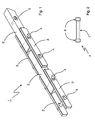
- Fig. 1 shows an oblique view of a section of a transport chain, which is used according to the invention for the transport of workpieces to be heated in a heating system.
- a transport chain constructed in this way could run through the heating area of a heating system and convey workpieces into the heating area.
- the transport chain 1 is made entirely of ceramic and comprises central blocks 2, which form a row in the longitudinal direction and which are arranged at a distance from each other.
- On the longitudinal sides of the blocks 2 a tab 3 is arranged on the left and right, which in the illustrated embodiment has substantially the same length as the blocks 2.
- the tabs 3 left and right of the blocks 2 each form a row in the longitudinal direction and are opposite the row of blocks 2 offset such that a tab 3 in its outer regions of the outer region of two adjacent blocks 2 touches.
- the thus touching tabs 3 and blocks 2 are interconnected via connectors 4. This results in a series of blocks 2, which are interconnected by means of tabs 3 and 4 connectors and at the same time allow movement in one direction.
- Each block 2 and each tab 3 has in the longitudinally outer regions each having a passage, which is formed in each case by two overlapping cylindrical holes.
- the center axes of the individual holes are arranged substantially perpendicular to the longitudinal direction of a block 2 or a tab 3 and substantially parallel to one another and in a plane.
- the longitudinally outer holes have a slightly smaller diameter than the holes further inward in the longitudinal direction.
- the connectors 4, which are used for joining the blocks 2 and the tabs 3 and which illustrate in more detail in FIG. 2, are formed by cylindrical elements which have a slightly larger diameter at the outer ends 7 than in the middle part 6.
- the middle part 6 is dimensioned such that its Length substantially corresponds to the width of the blocks 2 plus the width of two tabs 3 plus a certain degree of tolerance, so that a block 2 and two tabs 3 between the two ends 7 can be accommodated.
- the connectors 4 and the blocks 3 or lugs 4 are dimensioned such that the connectors 4 can be guided through the part of the passage 5 provided with a larger diameter and inserted into the feedthrough and into the other part of the feedthrough 5 shifted with the smaller diameter - can no longer be pulled longitudinally out of the passage 5.
- This embodiment of the bushings 5 and connector 4 ensures that the chain 1 can be joined together without difficulty, without a frictional connection between the connectors 4 and the tabs 3 or blocks 2 is necessary.
- the frictional connection often used in practice in chains would be connected in a chain of ceramic with very large problems.
- the configuration of the chain has the advantage that the connectors 4 lock in the bushings 5 when the chain 1 is loaded in the longitudinal direction. This can be achieved very easily by slightly tensioning the chain. If the chain is relaxed, however, the chain links 2, 3 and connector 4, for example, for maintenance, can be solved very easily.
- FIG. 3 shows the detail of the chain according to FIG. 1 in a side view (FIG. 3 a) or a top view (FIG. 3 b).
- FIG. 3 a shows the detail of the chain according to FIG. 1 in a side view (FIG. 3 a) or a top view (FIG. 3 b).
- FIG. 3 a shows the detail of the chain according to FIG. 1 in a side view (FIG. 3 a) or a top view (FIG. 3 b).
- a workpiece 8 which lies on the transport chain 1 is shown by way of example in FIG. 3 a.
- the section of the ceramic chain 1 shown in Fig. 1 and in Fig. 3 of two pairs of tabs 3 and two blocks 2 can be continued as desired.
- an arbitrarily long chain with a relatively arbitrary number of blocks 2 and pairs of tabs can be formed, which can also be designed as an endless chain.
- the chain can be widened in the transverse direction by repeatedly arranging the arrangement in the transverse direction.
- the blocks 2 may be made wider.
- the blocks 2 are designed plan and narrow.
- the blocks 2 can also be made wider and thereby provide a larger bearing surface for the workpieces.
- the blocks in the upper region could have recesses which are designed to receive the workpieces to be transported.
- the bottom of the blocks 2 have depressions that can take on the used for driving the chain sprocket (not shown).
Landscapes
- Engineering & Computer Science (AREA)
- General Engineering & Computer Science (AREA)
- Power Engineering (AREA)
- Physics & Mathematics (AREA)
- Electromagnetism (AREA)
- Mechanical Engineering (AREA)
- Tunnel Furnaces (AREA)
- Chain Conveyers (AREA)
- General Induction Heating (AREA)
Applications Claiming Priority (2)
| Application Number | Priority Date | Filing Date | Title |
|---|---|---|---|
| DE102006044038 | 2006-09-14 | ||
| DE102007011974.9A DE102007011974B4 (de) | 2006-09-14 | 2007-03-09 | Erwärmungsanlage, insbesondere Induktionserwärmungsanlage |
Publications (2)
| Publication Number | Publication Date |
|---|---|
| EP1900968A2 true EP1900968A2 (fr) | 2008-03-19 |
| EP1900968A3 EP1900968A3 (fr) | 2009-01-28 |
Family
ID=38796500
Family Applications (1)
| Application Number | Title | Priority Date | Filing Date |
|---|---|---|---|
| EP07015178A Withdrawn EP1900968A3 (fr) | 2006-09-14 | 2007-08-02 | Installation de chauffage, en particulier installation de chauffage à induction |
Country Status (2)
| Country | Link |
|---|---|
| EP (1) | EP1900968A3 (fr) |
| DE (1) | DE102007011974B4 (fr) |
Families Citing this family (1)
| Publication number | Priority date | Publication date | Assignee | Title |
|---|---|---|---|---|
| DE202010014412U1 (de) | 2010-10-16 | 2011-01-20 | Abp Induction Systems Gmbh | Fördereinrichtung |
Family Cites Families (7)
| Publication number | Priority date | Publication date | Assignee | Title |
|---|---|---|---|---|
| DE918739C (de) * | 1943-02-06 | 1954-10-04 | Porzellanfabrik Kahla | Durchlaufofen |
| US4582972A (en) * | 1984-08-22 | 1986-04-15 | General Motors Corporation | Chain feed mechanism for an induction heating furnace |
| DE4008979C1 (fr) * | 1990-03-21 | 1991-08-01 | Mahler Dienstleistungs-Gmbh Loeten-Haerten-Anlagenbau, 7300 Esslingen, De | |
| JPH0914849A (ja) * | 1995-06-28 | 1997-01-17 | Murata Mfg Co Ltd | 焼成炉用セラミックチェーン |
| US5816387A (en) * | 1996-09-16 | 1998-10-06 | Shaffer; Peter T. B. | High-temperature furnace and ceramic conveyer belt therefor |
| DE102004019959B4 (de) * | 2004-04-23 | 2008-02-21 | Freimut Storrer | Schleifwerkzeug |
| DE102004019950A1 (de) * | 2004-04-23 | 2005-11-17 | Fraunhofer-Gesellschaft zur Förderung der angewandten Forschung e.V. | Transportvorrichtung mit speziellen Kettengliedern zum Transport von zu prozessierenden Elementen durch eine Temperaturzone |
-
2007
- 2007-03-09 DE DE102007011974.9A patent/DE102007011974B4/de not_active Expired - Fee Related
- 2007-08-02 EP EP07015178A patent/EP1900968A3/fr not_active Withdrawn
Also Published As
| Publication number | Publication date |
|---|---|
| EP1900968A3 (fr) | 2009-01-28 |
| DE102007011974A1 (de) | 2008-04-17 |
| DE102007011974B4 (de) | 2016-03-10 |
Similar Documents
| Publication | Publication Date | Title |
|---|---|---|
| DE102006020781B3 (de) | Ofen | |
| DE4008979C1 (fr) | ||
| DE102007011974B4 (de) | Erwärmungsanlage, insbesondere Induktionserwärmungsanlage | |
| DE102015101356B4 (de) | Roststab mit Kühlmittel-Kanal | |
| EP0093877B1 (fr) | Dispositif pour le traitement thermique de pièces de matière à haute température | |
| DE102005049533B3 (de) | Mikrowellen-Durchlaufofen | |
| DE102019004618A1 (de) | Rollenherd-Durchlauf-Ofenanlage und Verfahren zur Erwärmung von mit Aluminium, Silizium und/oder Zink beschichteten Stahlplatinen auf Härte- und Presstemperatur | |
| DE102009019573A1 (de) | Ofen und Verfahren zum Erwärmen wenigstens eines Werkstückes | |
| DE102004020206A1 (de) | Verfahren zum Behandeln von Stranggussstangen oder Stranggussbolzen | |
| EP2944905B1 (fr) | Four de brûlage d'ébauches en céramique | |
| WO2011101231A1 (fr) | Dispositif de transport pour brames, doté d'au moins deux machines de coulée et d'au moins trois éléments transbordeurs | |
| EP1621840B1 (fr) | Four de traitement thermique à défilement | |
| AT394479B (de) | Einrichtung zum induktiven erwaermen von quaderfoermigen werkstuecken | |
| EP2295607A1 (fr) | Inducteur et utilisation d'un tel inducteur | |
| DE202004006551U1 (de) | Anlage zum Behandeln von Stranggussstangen oder Stranggussbolzen | |
| EP2298939A2 (fr) | Dispositif de chauffage inductif et utilisation d'un tel dispositif | |
| DE4203595A1 (de) | Vorrichtung zum abstuetzen von einsatzgut in einem erwaermungsofen | |
| DE1935921A1 (de) | Ofen zur thermischen Behandlung roehren- oder stabfoermigen Gutes aus keramischen oder diesen aehnlichen Massen | |
| DE2919207A1 (de) | Ofen zum erhitzen durchlaufender, zylindrischer teile | |
| EP1234152B1 (fr) | Four a passage continu pour produits a cuire tubulaires | |
| DE19738290A1 (de) | Fördereinrichtung zum Werkstücktransport in beheizbaren Anlagen | |
| DE3605725C1 (de) | Durchlaufofen | |
| DE976887C (de) | Waermofen mit mechanischer Waermgutfoerderung | |
| DE3149199A1 (de) | Foerdervorrichtung | |
| DE102005012783A1 (de) | Rollstab |
Legal Events
| Date | Code | Title | Description |
|---|---|---|---|
| PUAI | Public reference made under article 153(3) epc to a published international application that has entered the european phase |
Free format text: ORIGINAL CODE: 0009012 |
|
| AK | Designated contracting states |
Kind code of ref document: A2 Designated state(s): AT BE BG CH CY CZ DE DK EE ES FI FR GB GR HU IE IS IT LI LT LU LV MC MT NL PL PT RO SE SI SK TR |
|
| AX | Request for extension of the european patent |
Extension state: AL BA HR MK YU |
|
| PUAL | Search report despatched |
Free format text: ORIGINAL CODE: 0009013 |
|
| AK | Designated contracting states |
Kind code of ref document: A3 Designated state(s): AT BE BG CH CY CZ DE DK EE ES FI FR GB GR HU IE IS IT LI LT LU LV MC MT NL PL PT RO SE SI SK TR |
|
| AX | Request for extension of the european patent |
Extension state: AL BA HR MK RS |
|
| AKX | Designation fees paid | ||
| STAA | Information on the status of an ep patent application or granted ep patent |
Free format text: STATUS: THE APPLICATION IS DEEMED TO BE WITHDRAWN |
|
| 18D | Application deemed to be withdrawn |
Effective date: 20090729 |
|
| REG | Reference to a national code |
Ref country code: DE Ref legal event code: 8566 |