EP1901030A2 - Agencement de mesure et procédé de détection de la surface d'objets - Google Patents
Agencement de mesure et procédé de détection de la surface d'objets Download PDFInfo
- Publication number
- EP1901030A2 EP1901030A2 EP07017869A EP07017869A EP1901030A2 EP 1901030 A2 EP1901030 A2 EP 1901030A2 EP 07017869 A EP07017869 A EP 07017869A EP 07017869 A EP07017869 A EP 07017869A EP 1901030 A2 EP1901030 A2 EP 1901030A2
- Authority
- EP
- European Patent Office
- Prior art keywords
- sensor
- mirror
- measuring
- detected
- measuring arrangement
- Prior art date
- Legal status (The legal status is an assumption and is not a legal conclusion. Google has not performed a legal analysis and makes no representation as to the accuracy of the status listed.)
- Withdrawn
Links
Images
Classifications
-
- G—PHYSICS
- G01—MEASURING; TESTING
- G01B—MEASURING LENGTH, THICKNESS OR SIMILAR LINEAR DIMENSIONS; MEASURING ANGLES; MEASURING AREAS; MEASURING IRREGULARITIES OF SURFACES OR CONTOURS
- G01B11/00—Measuring arrangements characterised by the use of optical techniques
- G01B11/24—Measuring arrangements characterised by the use of optical techniques for measuring contours or curvatures
-
- G—PHYSICS
- G01—MEASURING; TESTING
- G01N—INVESTIGATING OR ANALYSING MATERIALS BY DETERMINING THEIR CHEMICAL OR PHYSICAL PROPERTIES
- G01N21/00—Investigating or analysing materials by the use of optical means, i.e. using sub-millimetre waves, infrared, visible or ultraviolet light
- G01N21/84—Systems specially adapted for particular applications
- G01N21/88—Investigating the presence of flaws or contamination
- G01N21/95—Investigating the presence of flaws or contamination characterised by the material or shape of the object to be examined
- G01N21/952—Inspecting the exterior surface of cylindrical bodies or wires
Definitions
- the invention relates to a measuring arrangement for detecting the surface or parts of the surface of three-dimensionally extended objects by means of an optical sensor, wherein the sensor has a measuring range extending transversely to the optical axis of the sensor and wherein the object to be detected at least partially in the measuring range of the sensor located.
- the invention further relates to a corresponding method.
- the structure of the surface, the color, the color gradient or other properties of the surface are detected with an optical sensor.
- the results of the acquisition are converted into digital form, suitably reworked and stored.
- the detection can serve a variety of purposes. Thus, the determination of the profile of the surface, the recognition of individual structures on or in the surface, the measurement of the dimension of the object, the detection of production errors or the like in the foreground.
- the recognition of production errors is of great importance in the industrial context. If an error is detected, defective parts can be discarded early in a production chain or fed to a post-processing, before the errors lead to high costs or production losses, for example, in later production steps.
- the problem with such conditions of use is that the detection must provide information quickly and extremely reliably, without hindering the production and causing high costs of the production facility. For example, in the manufacture of pipes, profiled bars or continuous material, the product is moved past the sensor at a comparatively high speed. This requires the simultaneous detection of the surface at different locations around the circumference of the object.
- the present invention is therefore based on the object to design a measuring arrangement of the type mentioned and further, that the surface or parts of the surface of three-dimensionally extended objects reached as cost-effective and with simple design of the measuring arrangement even when detecting the surface over the entire circumference can be.
- a corresponding method, in particular for operating such a measuring arrangement, should be specified.
- the above object is solved by the features of claim 1.
- the measuring arrangement in question is developed such that the measuring arrangement comprises a mirror arrangement with one or more mirrors, wherein the mirror (s) of the mirror arrangement are arranged such that a part of the measuring area which passes the object to be detected unused, by the / the mirror is directed to the surface of the object to be detected.
- the above object is achieved by the features of claim 12. Thereafter, the method in question is characterized in that a part of the measuring range, which passes the object to be detected unused, is directed by means of a mirror arrangement on the surface of the object to be detected and thereby not directly detectable parts of the object are detected,
- the optical sensor is arranged such that the object to be detected uses only a part of the measuring range of the sensor transversely to the optical axis of the sensor.
- this is not a real limitation in many applications.
- the measuring arrangement according to the invention does not impose any restrictions as to how the ratio between the directly used measuring range and the measuring range used via the mirror arrangement must be.
- the ratio will be chosen such that a direct detection of the object is performed in the range of 40 to 70% of the measuring range.
- higher and lower percentages may be useful. So it may be useful for specially designed to be detected objects to capture the surface as vertical as possible. This can be achieved by the measuring arrangement according to the invention in that only a very small proportion of the available measuring range is used for the direct detection of the surface, while a much larger proportion is used for detecting the surface via the mirror arrangement.
- the sensor used in the measuring arrangement according to the invention is a distance sensor.
- This can be designed to capture two- or three-dimensional data.
- the sensor works according to the light-section method, in which a narrow and bright as possible Line is projected onto the project to be detected and the light beam reflected on the surface is detected by a detector array. From the displacement of the line in the detected image can be concluded on the three-dimensional nature of the surface.
- other distance sensors can be used instead of these so-called line triangulators.
- confocal, confocal chromatic and autofocus systems are noted.
- the detection of the surface can be done both pointwise and along any line or surface. At the same time, detection can take place both with and without displacement of the sensor or of the object to be detected relative to one another.
- the sensor has an opto-electrical detector, which can be designed as a line detector or matrix detector.
- the detector can be designed as a simple row of photodiodes, but could also comprise a CCD camera. In principle, all known from practice opto-electrical detectors can be used.
- a lighting device which illuminates the surface to be detected.
- This lighting device can be realized by a variety of known from practice light sources.
- the illumination source will be selected depending on the measurement method used.
- the illumination device comprises, for example, a line laser projector and is an integral part of the sensor system.
- the sensor could already have on its own a measuring range extending transversely to its optical axis.
- this extension of the measuring range could also be achieved by appropriate measures.
- the expansion of the measuring range could also be achieved by movement of the sensor transversely to its optical axis. Depending on the desired speed, with If the information is to be obtained by the sensor, a suitable means will be chosen here.
- the senor could be followed by suitable optics, for example a telecentric optic.
- the senor as a distance sensor further embodiments of the sensor are possible.
- the area of the surface which can be scanned simultaneously can be increased by the measuring arrangement according to the invention.
- the mirrors used could have a wide variety of geometrical configurations.
- the surface of the mirror is flat.
- the mirrors could also consist of sections of spheres, cylinders, ellipsoids, hyperboloids or the like. The choice of a suitable mirror surface will generally depend on the application situation.
- the mirror arrangement consists of several mirrors, then not all mirrors need to be executed in the same way. Rather, it is possible that differently configured mirrors are used in a mirror arrangement.
- a number of mirrors could be used in succession to guide the measuring area to the surface. Accordingly, a first mirror could not direct the measuring area to the surface of the object but instead to a second mirror, which could then direct the measuring area onto the object itself or another mirror.
- the mirrors may also be formed by a variety of reflective surfaces.
- metallised glass surfaces can be used as well as highly polished metal surfaces. In principle, all techniques known from practice can be used for this purpose.
- the mirror could be made movable. This movement could be translational, rotational or as a combination of both.
- the rotation and translation axes can be relatively arbitrarily oriented. Due to the mobility of the mirror, the measuring arrangement can be adapted to the respective object to be detected. The adaptation could also take place during the measuring process.
- the movement of the mirror can be done manually or automatically. With an automatic adjustment of the mirrors, the movement could be controlled by a control unit. This could ensure a traceable change in the mirror position and position.
- the measuring arrangement and the object to be detected could be designed to be displaceable relative to one another. It is insignificant whether a shift of the measuring arrangement or the object is made. It would also be conceivable to move both the measuring arrangement and the object. The direction of the movement is basically irrelevant. Here, the respective application will decide which approach makes sense. It would also be conceivable that the measuring arrangement is attached to a robot arm and, if necessary, is pivoted in the direction of the object to be detected.
- an image obtained by the sensor contains various components to be interpreted. So there are shares that reflect the surface itself. These result from the direct detection of the surface. In addition, however, shares are also available whose information can only be used clearly after a post-processing. These proportions result from the detection of the surface using the mirror assembly. A subsequent signal acquisition could separate these portions accordingly. If the sensor is a distance sensor, then the change between the areas detected directly and the areas detected via the mirror arrangement will manifest itself in a significant distance jump. This jump can then be used to separate the areas. Additionally or alternatively, knowledge about the geometry of the measuring arrangement could be used.
- the object to be detected appears behind the mirror. This manifests itself in the fact that a greater distance between the sensor and the object is determined than the distance between sensor and mirror would permit. If the distance of the sensor from a mirror surface is known, this information can be used to separate the portions of the sensor image. Since no measurement object can be detected behind the mirror, it is a fraction that has been detected by a mirror. In particular, when using other sensors may be necessary to use knowledge of the object to be detected.
- the signals of the sensor may need to be digitized by an analog-to-digital converter.
- analog-to-digital converter For this purpose, a variety of methods are known from practice. The signal processing itself could be done in suitable digital computers. There are also all known from practice computers available. By way of example only, reference may be made to the use of DSPs (Digital Signal Processor), microcontrollers, Field Programmable Gate Array (FPGA), Complex Programmable Logic Device (CPLD), Application Specific Integrated Circuit (ASIC), or combinations of these technologies. However, signal processing could also be performed on a PC with possibly additional hardware.
- DSPs Digital Signal Processor
- FPGA Field Programmable Gate Array
- CPLD Complex Programmable Logic Device
- ASIC Application Specific Integrated Circuit
- various information about the surface of the scanned object could be reconstructed. For example, an overall profile of the surface can be calculated using the geometric configuration of the measuring arrangement from a distance image of the sensor.
- the dimensions of the object or of individual areas of the object could also be determined. These dimensions may include, for example, the thickness of the object.
- the information obtained by the sensor could be used to find specific locations on the object. These locations may include, for example, manufacturing defects in an object or special markings.
- the measuring arrangement according to the invention can also be used multiple times.
- the measuring arrangement can be used multiple times to detect an object along its circumference.
- the number of required sensors can be significantly reduced by the enlarged on the surface simultaneously detectable by a sensor area.
- the number of control units needed to control the individual sensors and the necessary additional equipment such as analog-to-digital converters is reduced.
- the signal processing can be done more rational and cheaper.
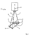
- FIG. 1 shows a measuring arrangement 1 according to the invention for detecting the surface 2 of an object 3 by means of a sensor 4.
- the sensor 4 has a measuring area extending transversely to its optical axis 5, whose edge beams are given by the light beams 6 and 7.
- Another light beam 8 in the measuring range is shown in FIG. 1 between the marginal rays 6, 7.
- Light beam 8 characterizes the light beam that just passes the object 3.
- the illuminating rays located between the light beams 7 and 8 are reflected by the surface 2 of the object 3 and impinge on a detector of the sensor 4 Light rays thus serve the direct detection of the surface.
- the light rays between the light beams 6 and 8 pass through the object 3 and would be lost unused in measuring arrangements known from the prior art.
- a mirror 9 which directs the passing light rays back onto the object 3. These illumination light beams are then reflected by the surface 2 of the object 3 and reflected again via mirror 9. From here they enter the detector of the sensor 4. The light rays located between the light beams 6 and 8 thus serve for the indirect detection of the surface.
- the unused measuring range of the sensor can be used by the measuring arrangement according to the invention on the one hand.
- the otherwise undetectable underside of the object 3 can be detected. From the information obtained in this way, properties of the surface 2 of the object 3 can be reconstructed.
- the sensor 4 used is a distance sensor, the profile of the top and bottom of the object 3 can be reconstructed.
- the thickness d of the object 3 can be determined.
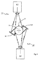
- Fig. 2 shows the detection of the surface 2 of an object 3 over its entire circumference.
- the detected object 3 may, for example, be a tube which is to be examined after production and moves perpendicular to the plane of the drawing in FIG.
- the measuring arrangement shown in FIG. 1 is used in duplicate, wherein the two measuring arrangements are rotated by 180 °.
- a sensor 4.1 or 4.2 in turn illuminates the surface 2 of an object 3.
- the light rays illuminate the object 3 directly to a part, to another part they are directed to the surface 2 of the object 3 via a mirror 9.1 or 9.2.
- FIG. 2 clearly shows that, by using the measuring arrangement according to the invention, the surface 2 of the object 3 can be detected over the entire circumference.
- the number of sensors used can be reduced to two by the measuring arrangement according to the invention. Nevertheless, the entire circumference of the object 3 is detectable.
Landscapes
- Physics & Mathematics (AREA)
- General Physics & Mathematics (AREA)
- Health & Medical Sciences (AREA)
- Life Sciences & Earth Sciences (AREA)
- Chemical & Material Sciences (AREA)
- Analytical Chemistry (AREA)
- Biochemistry (AREA)
- General Health & Medical Sciences (AREA)
- Immunology (AREA)
- Pathology (AREA)
- Length Measuring Devices By Optical Means (AREA)
Applications Claiming Priority (2)
| Application Number | Priority Date | Filing Date | Title |
|---|---|---|---|
| DE102006043740 | 2006-09-13 | ||
| DE102007007192A DE102007007192A1 (de) | 2006-09-13 | 2007-02-09 | Messanordnung und Verfahren zum Erfassen der Oberfläche von Objekten |
Publications (2)
| Publication Number | Publication Date |
|---|---|
| EP1901030A2 true EP1901030A2 (fr) | 2008-03-19 |
| EP1901030A3 EP1901030A3 (fr) | 2010-06-23 |
Family
ID=38669579
Family Applications (1)
| Application Number | Title | Priority Date | Filing Date |
|---|---|---|---|
| EP07017869A Withdrawn EP1901030A3 (fr) | 2006-09-13 | 2007-09-12 | Agencement de mesure et procédé de détection de la surface d'objets |
Country Status (1)
| Country | Link |
|---|---|
| EP (1) | EP1901030A3 (fr) |
Cited By (5)
| Publication number | Priority date | Publication date | Assignee | Title |
|---|---|---|---|---|
| WO2009058247A1 (fr) * | 2007-10-31 | 2009-05-07 | Corning Incorporated | Systèmes de mesure par balayage laser et procédés de mesure de forme de surface de surfaces cachées |
| DE102010036762A1 (de) * | 2010-06-16 | 2011-12-22 | Wincor Nixdorf International Gmbh | Verfahren und Vorrichtung zur Formerkennung von Leergutgebinden in Leergutrücknahmeautomaten mittels eines Lichtschnitt Triangulationsverfahren |
| ITUB20155673A1 (it) * | 2015-11-18 | 2017-05-18 | Gd Spa | Unita di ispezione di un elemento allungato. |
| ITUB20155646A1 (it) * | 2015-11-18 | 2017-05-18 | Gd Spa | Metodo di ispezione di un elemento allungato. |
| CN108120398A (zh) * | 2017-12-27 | 2018-06-05 | 大连鉴影光学科技有限公司 | 一种立体镜面曲面的面形检测方法和装置 |
Family Cites Families (4)
| Publication number | Priority date | Publication date | Assignee | Title |
|---|---|---|---|---|
| DE3805455A1 (de) * | 1988-02-22 | 1989-08-31 | Linck Masch Gatterlinck | Vorrichtung zum fotoelektrischen abtasten und/oder vermessen von holzerzeugnissen |
| WO2001094922A1 (fr) * | 1997-10-28 | 2001-12-13 | Materials Technologies Corporation | Appareil et procede permettant de visionner et d'inspecter une region de surface circonferencielle d'un objet |
| AU2002226671B2 (en) * | 2001-02-01 | 2006-08-31 | Marel Hf. | Method and apparatus for determining a three dimensional image of a moving object by means of light |
| US20030072011A1 (en) * | 2001-10-09 | 2003-04-17 | Shirley Lyle G. | Method and apparatus for combining views in three-dimensional surface profiling |
-
2007
- 2007-09-12 EP EP07017869A patent/EP1901030A3/fr not_active Withdrawn
Cited By (12)
| Publication number | Priority date | Publication date | Assignee | Title |
|---|---|---|---|---|
| WO2009058247A1 (fr) * | 2007-10-31 | 2009-05-07 | Corning Incorporated | Systèmes de mesure par balayage laser et procédés de mesure de forme de surface de surfaces cachées |
| DE102010036762A1 (de) * | 2010-06-16 | 2011-12-22 | Wincor Nixdorf International Gmbh | Verfahren und Vorrichtung zur Formerkennung von Leergutgebinden in Leergutrücknahmeautomaten mittels eines Lichtschnitt Triangulationsverfahren |
| DE102010036762B4 (de) * | 2010-06-16 | 2017-12-28 | Wincor Nixdorf International Gmbh | Verfahren und Vorrichtung zur Formerkennung von Leergutgebinden in Leergutrücknahmeautomaten mittels eines Lichtschnitt Triangulationsverfahren |
| ITUB20155673A1 (it) * | 2015-11-18 | 2017-05-18 | Gd Spa | Unita di ispezione di un elemento allungato. |
| ITUB20155646A1 (it) * | 2015-11-18 | 2017-05-18 | Gd Spa | Metodo di ispezione di un elemento allungato. |
| WO2017085662A1 (fr) * | 2015-11-18 | 2017-05-26 | G.D. S.P.A. | Groupe d'inspection d'un élément allongé |
| WO2017085659A1 (fr) * | 2015-11-18 | 2017-05-26 | G.D. S.P.A. | Procédé d'inspection d'un élément allongé |
| KR20180083344A (ko) * | 2015-11-18 | 2018-07-20 | 쥐.디 에스.피.에이. | 신장된 요소를 검사하는 방법 |
| US10302418B2 (en) | 2015-11-18 | 2019-05-28 | G.D. S.P.A. | Inspection group of an elongated element |
| US10299506B2 (en) | 2015-11-18 | 2019-05-28 | G.D S.P.A. | Method for inspecting an elongated element |
| KR102337014B1 (ko) * | 2015-11-18 | 2021-12-09 | 쥐.디 에스.피.에이. | 신장된 요소를 검사하는 방법 |
| CN108120398A (zh) * | 2017-12-27 | 2018-06-05 | 大连鉴影光学科技有限公司 | 一种立体镜面曲面的面形检测方法和装置 |
Also Published As
| Publication number | Publication date |
|---|---|
| EP1901030A3 (fr) | 2010-06-23 |
Similar Documents
| Publication | Publication Date | Title |
|---|---|---|
| DE112009001650B4 (de) | Lochinspektionsverfahren und -vorrichtung | |
| DE3123703A1 (de) | Optisches messsystem mit einer fotodetektoranordnung | |
| DE4136002A1 (de) | Moire- konturenabbildungsvorrichtung | |
| DE102015102111A1 (de) | Mehrkopf-Laseranlage mit Sensoreinheit | |
| EP1640688A1 (fr) | Procédé et dispositif pour mesurer la surface d'un objet en trois dimensions | |
| DE102007007192A1 (de) | Messanordnung und Verfahren zum Erfassen der Oberfläche von Objekten | |
| EP1901031B1 (fr) | Agencement de mesure et procédé de mesure d'une structure étirée de manière tridimensionnelle | |
| DE102019201272B4 (de) | Vorrichtung, Vermessungssystem und Verfahren zur Erfassung einer zumindest teilweise spiegelnden Oberfläche unter Verwendung zweier Spiegelungsmuster | |
| DE102022116214B4 (de) | Messkamera und Verfahren zur zweidimensionalen Vermessung von Gegenständen | |
| DE102009015627B4 (de) | Verfahren und Vorrichtung zu Bestimmung von Innendurchmesser, Außendurchmesser und der Wandstärke von Körpern | |
| WO1999039232A1 (fr) | Dispositif de balayage optique d'un objet | |
| DE4011407A1 (de) | Vorrichtung zur quantitativen absolutvermessung der dreidimensionalen koordinaten eines pruefobjekts | |
| DE102007007194A1 (de) | Messanordnung und Verfahren zum Vermessen einer dreidimensionalen ausgedehnten Struktur | |
| EP3899423B1 (fr) | Dispositif, système de mesure et procédé pour la détection d'une surface au moins partiellement réfléchissante par l'utilisation de deux motifs de réflexion | |
| WO2007134739A1 (fr) | Système et procédé de détermination tridimensionnelle de la surface d'un objet | |
| EP3575741B1 (fr) | Procédé de mesure sans contact d'un bord de pièce à usiner | |
| EP2799847B1 (fr) | Procédé de contrôle optique de surfaces d'objets | |
| DE102017111819B4 (de) | Bohrungsinspektionsvorrichtung | |
| DE102020110298A1 (de) | Vorrichtung und Verfahren zur optischen Messung einer Oberflächentopographie | |
| DE102006052047A1 (de) | Verfahren und Vorrichtung zur Bestimmung der Lage einer Symmetrieachse einer asphärischen Linsenfläche | |
| DE102022115880A1 (de) | Deflektometrie-Sensorsystem zur Vermessung und Erfassung von Oberflächendefekten spiegelnder Flächen | |
| DE102004020881A1 (de) | Verfahren und Vorrichtung zum geometrischen Kalibrieren von optoelektronischen Messbildkameras | |
| DE102010029627A1 (de) | Vorrichtung und Verfahren zur Bestimmung der Struktur einer spiegelnden Oberfläche eines Objekts | |
| DE102004046752B4 (de) | Verfahren zur dreidimensionalen Erfassung von Messobjekten | |
| AT521620B1 (de) | Mikroskopie-Vorrichtung zur Erstellung dreidimensionaler Abbilder |
Legal Events
| Date | Code | Title | Description |
|---|---|---|---|
| PUAI | Public reference made under article 153(3) epc to a published international application that has entered the european phase |
Free format text: ORIGINAL CODE: 0009012 |
|
| AK | Designated contracting states |
Kind code of ref document: A2 Designated state(s): AT BE BG CH CY CZ DE DK EE ES FI FR GB GR HU IE IS IT LI LT LU LV MC MT NL PL PT RO SE SI SK TR |
|
| AX | Request for extension of the european patent |
Extension state: AL BA HR MK YU |
|
| RIN1 | Information on inventor provided before grant (corrected) |
Inventor name: SCHUELLER, TOBIAS, DR.-ING. Inventor name: STAUTMEISTER, TORSTEN, DIPL.-ING. |
|
| PUAL | Search report despatched |
Free format text: ORIGINAL CODE: 0009013 |
|
| AK | Designated contracting states |
Kind code of ref document: A3 Designated state(s): AT BE BG CH CY CZ DE DK EE ES FI FR GB GR HU IE IS IT LI LT LU LV MC MT NL PL PT RO SE SI SK TR |
|
| AX | Request for extension of the european patent |
Extension state: AL BA HR MK RS |
|
| AKY | No designation fees paid | ||
| STAA | Information on the status of an ep patent application or granted ep patent |
Free format text: STATUS: THE APPLICATION IS DEEMED TO BE WITHDRAWN |
|
| 18D | Application deemed to be withdrawn |
Effective date: 20101224 |