EP1901042A1 - Dispositif de mesure de débit - Google Patents
Dispositif de mesure de débit Download PDFInfo
- Publication number
- EP1901042A1 EP1901042A1 EP06746889A EP06746889A EP1901042A1 EP 1901042 A1 EP1901042 A1 EP 1901042A1 EP 06746889 A EP06746889 A EP 06746889A EP 06746889 A EP06746889 A EP 06746889A EP 1901042 A1 EP1901042 A1 EP 1901042A1
- Authority
- EP
- European Patent Office
- Prior art keywords
- flow
- channel
- flow channel
- centrifugal chamber
- wall surface
- Prior art date
- Legal status (The legal status is an assumption and is not a legal conclusion. Google has not performed a legal analysis and makes no representation as to the accuracy of the status listed.)
- Granted
Links
Images




Classifications
-
- G—PHYSICS
- G01—MEASURING; TESTING
- G01F—MEASURING VOLUME, VOLUME FLOW, MASS FLOW OR LIQUID LEVEL; METERING BY VOLUME
- G01F5/00—Measuring a proportion of the volume flow
-
- G—PHYSICS
- G01—MEASURING; TESTING
- G01F—MEASURING VOLUME, VOLUME FLOW, MASS FLOW OR LIQUID LEVEL; METERING BY VOLUME
- G01F1/00—Measuring the volume flow or mass flow of fluid or fluent solid material wherein the fluid passes through a meter in a continuous flow
- G01F1/68—Measuring the volume flow or mass flow of fluid or fluent solid material wherein the fluid passes through a meter in a continuous flow by using thermal effects
- G01F1/684—Structural arrangements; Mounting of elements, e.g. in relation to fluid flow
-
- G—PHYSICS
- G01—MEASURING; TESTING
- G01F—MEASURING VOLUME, VOLUME FLOW, MASS FLOW OR LIQUID LEVEL; METERING BY VOLUME
- G01F15/00—Details of, or accessories for, apparatus of groups G01F1/00 - G01F13/00 insofar as such details or appliances are not adapted to particular types of such apparatus
- G01F15/12—Cleaning arrangements; Filters
-
- G—PHYSICS
- G01—MEASURING; TESTING
- G01F—MEASURING VOLUME, VOLUME FLOW, MASS FLOW OR LIQUID LEVEL; METERING BY VOLUME
- G01F15/00—Details of, or accessories for, apparatus of groups G01F1/00 - G01F13/00 insofar as such details or appliances are not adapted to particular types of such apparatus
- G01F15/14—Casings, e.g. of special material
Definitions
- the present invention relates to a flow rate measuring device, for example, a small sized flow rate measuring device used for an industrial equipment for monitoring an air flow rate in factories, a medical equipment such as a therapeutic instrument for sleep apnea syndrome.
- a flow rate measuring device has a construction in which a detection element is placed in a flow channel and an air flow rate is measured.
- dust in air adheres to and accumulates on the detection element, and measurement accuracy deteriorates. This may become a cause of failure.
- Patent Document 1 JP11-166720A
- the above dust trap device separates dust by means of utilizing only the inertial force of dust that goes straight, if a flow velocity of air is low, an ability to separate dust from the air deteriorates and it is difficult to catch dust reliably. Further, even if dust can be caught by the trap walls, there is fear that dust that has accumulated by a long-term use falls into or is included in a flow channel on the detection element side. In particular, the dust trap device can only catch dust in an airflow flowing from one direction, and cannot cope with an airflow flowing from the opposite direction. Thus, there is a problem that a flow rate of a fluid flowing from two directions cannot be detected.
- an object of the present invention is to provide a flow rate measuring device which can reliably separate dust from a fluid and can prevent a defect due to inclusion of dust despite its long-term use, in particular a flow rate measuring device which can also cope with a fluid flowing from two directions.
- a flow rate measuring device of the present invention in which a flow channel is formed, said flow channel comprising:
- a centrifugal force acts on dust that has flowed into the centrifugal chamber from the guiding flow channel, and the dust flows along the wall surface of the centrifugal chamber, so that only a clean fluid flows into the detection element from the flow dividing channel. Therefore, the dust does not adhere to or accumulate on the detection element and it is possible to prevent deterioration in measurement accuracy of the detection element or failure of the detection element. Further, since the separated dust is discharged from the centrifugal chamber together with the fluid, accumulation of dust is small despite its long-term use. Therefore, a flow rate measuring device which is easy in maintenance and has a long lifetime can be obtained.
- a flow channel forming plate is interposed between a first layer base plate and a second layer base plate; between the first layer base plate and the flow channel forming plate, the centrifugal chamber having the curved wall surface, the guiding flow channel allowing the external flow channel to communicate with said one end of the wall surface of the centrifugal chamber from the tangential direction thereof, and the discharge flow channel communicating with said the other end of the wall surface of the centrifugal chamber from the tangential direction thereof are formed; and, between the flow channel forming plate and the second layer base plate, a flow dividing channel, which communicates with the centrifugal chamber through a flow dividing hole provided in the flow channel forming plate, and in which a detection element is placed on its downstream side, is formed, a fluid that has been introduced into the centrifugal chamber from the external flow channel through the guiding flow channel is divided with the discharge flow channel and the flow dividing channel, and a flow rate of a fluid taken out from the flow dividing channel is measured
- the guiding flow channel may be formed so as to be inclined in a direction opposite to a flow direction of the external flow channel. According to the present embodiment, since the guiding flow channel is inclined in the direction opposite to the flow direction of the external flow channel, a flow velocity increases by the gushing effect of the flow and it is possible to enhance the centrifugal separation effect on dust.
- a centrifugal force acts on dust that has flowed into the first and second centrifugal chambers from the first and second guiding channels respectively, and the dust flows along the wall surfaces of the first and second centrifugal chambers, so that only a clean fluid flows into the detection element from the first and second flow dividing channels. Therefore, the dust does not adhere to or accumulate on the detection element, and it is possible to prevent deterioration in measurement accuracy or failure of the detection element. Further, since the separated dust is discharged into the first and second external flow channels together with the fluid, accumulation of dust is small despite its long-term use. Therefore, a flow rate measuring device which is easy in maintenance and has a long lifetime can be obtained. In particular, according to the present invention, it is possible to cope with a fluid flowing from two directions by the pair of centrifugal chambers, and a versatile flow rate measuring device is obtained.
- a flow channel forming plate is interposed between a first layer base plate and a second layer base plate; between the first layer base plate and the flow channel forming plate, a pair of first and second centrifugal chambers each having a curved wall surface, a first guiding flow channel allowing a first external flow channel to communicate with one end of the wall surface of the first centrifugal chamber from a tangential direction thereof, an intermediate flow channel communicating with the other end of the wall surface of the first centrifugal chamber from a tangential direction thereof, as well as communicating with one end of the wall surface of the second centrifugal chamber from a tangential direction thereof, and a second guiding flow channel allowing a second external flow channel to communicate with the other end of the wall surface of the second centrifugal chamber from a tangential direction thereof are formed; and, between the flow channel forming plate and the second layer base plate, a first flow dividing channel communicating with the first centrifugal chamber, generally perpendicular to
- complicated three dimensional flow channels can easily be formed by a combination of the first layer base plate and the second layer base plate, and the manufacture is facilitated.
- each of the first and second guiding flow channels may be formed so as to be inclined in a direction opposite to a flow direction of each of the first and second external flow channels. According to the present embodiment, since each of the guiding flow channels is inclined in the direction opposite to the flow direction of each of the first and second external flow channels, a flow velocity increases by a gushing effect of the fluid that flows and it is possible to enhance a centrifugal separation effect on dust.
- the intermediate flow channel may be bent in a generally V-shape.
- a flow velocity in the discharge side centrifugal chamber increases, and a greater centrifugal force acts thereon, so that it becomes easier to discharge dust.
- the centrifugal chamber may have a cylindrical shape. According to the present embodiment, since a fluid flow forms a circle, the centrifugal force acts toward the wall surface in a manner so as to be always perpendicular to a fluid flow direction, dust separation efficiency is high.
- one end of the flow dividing channel may be formed of a cylindrical portion protruding into the centrifugal chamber. According to the present embodiment, for example, even if the flow dividing channel is placed so as to be located at a bottom surface of the centrifugal chamber, dust separated from the fluid flow due to gravitation cannot flow over the cylindrical portion, so that there is an effect that dust is prevented from flowing into the flow dividing channel more.
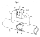
- a flow rate measuring device 10 of the present embodiment is connected to a primary flow pipe 11 through a first connection pipe and a second connection pipe 12, 13.
- the first and second connection pipe 12, 13 are connected to an upstream side and a downstream side, respectively, of a primary flow channel 15 passing through an annular orifice 14 formed on an inner peripheral surface of the primary flow pipe mm 11.
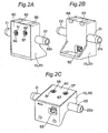
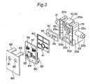
- the flow rate measuring device 10 is constructed of a base 20, a flow channel forming plate 30, a plate-like sealing member 40, a circuit board 50 and a cover 60.
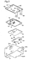
- the base 20 has, on its rear surface side, a recessed portion 23 for housing internal components, which will be described below, and a recess 24 having a deeper depth than that of the recessed portion 23 is formed in one side portion of a bottom surface of the recessed portion 23. Further, as shown in Fig. 7 , a pair of left and right first and second centrifugal chambers 25, 26 are formed in a bottom surface of the recess 24.
- the first and the second centrifugal chamber 25, 26 communicate with a first and a second secondary flow channel 21a, 22a of the first and the second inlet/outlet pipe 21, 22 through a first and a second guiding flow channel 27, 28, respectively.
- the first and second centrifugal chambers 25, 26 communicate with each other through an intermediate flow channel 29 bent in a generally V-shape.
- the first guiding flow channel 27 is formed so as to be inclined in a direction opposite to a flow direction of the first secondary flow channel 21a, while the second guiding flow channel 28 is formed so as to be line symmetrical with respect to the first guiding flow channel 27.
- a detection space portion 23b is formed in a manner so as to communicate with the recess 24 through a J-shaped communication flow channel 23a. Furthermore, a connector hole 23c is formed on one side of the bottom surface of the recessed portion 23, and a connector hole 23d is also provided on an inner surface of the recessed portion 23.
- Angles of the first and the second guiding flow channel 27, 28 with respect to the first and the second secondary flow channel 21a, 22a are each 45° or more and less than 90°, preferably 55° or more and less than 90°. The reason therefor is that if each angle is less than 45°, a pressure loss becomes too large, and if the angle is 90°C or more, a desired centrifugal force is not obtained.
- the intermediate flow channel 29 have an inclination generally parallel to the first and second guiding flow channels 27, 28. Specifically, it is 50° or more and less than 180°, preferably 80° or more and less than 180°. The reason therefor is that if it is less than 50°, a pressure loss becomes too large, and if it is 180° or more, a desired centrifugal force is not obtained.
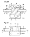
- the flow channel forming plate 30 has a planar shape that can be fitted into the recess 24, and is formed with a first and a second flow dividing hole 31, 32 in positions corresponding to the first and the second centrifugal chamber 25, 26, respectively.
- a lower surface of the flow channel forming plate 30 is formed with a first and a second cylindrical portion 33, 34, which communicate with the first and the second flow dividing hole 31, 32, respectively.
- an upper surface of the flow channel forming plate 30 is formed with a first and a second flow dividing channel 35, 36, which communicate with the first and the second centrifugal chamber 25, 26 from the first and the second flow dividing hole 31, 32, respectively.
- the first and second flow dividing channels 35, 36 can communicate with the communication flow channel 23a and the detection space portion 23b, respectively.
- the first and second cylindrical portions 33, 34 preferably have a height dimension of about one third to two thirds of that of the first and second centrifugal chambers 25, 26, particularly about 50% thereof. The reason therefor is that if the first and second cylindrical portions 33, 34 are too short, dust is liable to be included, while if the first and second cylindrical portions 33, 34 are too long, a fluid becomes hard to flow into the first and second flow dividing channels smoothly.
- a flow dividing ratio of a flow rate of a fluid discharged to the intermediate flow channel 29 to a flow rate of a fluid flowing through the detection space portion 23b can be adjusted. Therefore, even if the flow rates to be measured are largely different from each other, the flow rates can easily be adjusted by merely replacing the flow channel forming plate 30 having the flow dividing holes 31, 32 with a flow channel forming plate having flow dividing holes with different diameters. As a result, there is an advantage that an optimal specification can be provided without changing a detection element 51 described below, which is expensive and takes time for replacement.
- the plate-like sealing member 40 has a planar shape that can be fitted into the recessed portion 23 of the base 20, and is provided with a detection opening 41 in a position corresponding to the detection space portion 23b. Therefore, by fitting the plate-like sealing member 40 into the recessed portion 23 of the base 20, the detection space portion 23b of the base 20 can be visually checked from the detection opening 41.
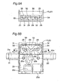
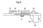
- the circuit board 50 has a planar shape that can be fitted into the recessed portion 23 of the base 20, and on its front face, a detection element 51 is placed at a position corresponding to the detection space portion 23b of the base 20, and connectors 52, 53 are placed at positions corresponding to the connector holes 23c, 23d on the base 20, respectively.
- the detection element 51 include a MEMS flow sensor and a propeller type sensor, for example.
- a control element 54 and a voltage-adjusting element 55 are mounted, and adjusting elements 56, 57 that are operable from outside are placed.
- the detection element 51 is positioned in the detection space portion 23b, the connectors 52, 53 are fitted into the connector holes 23c, 23d, respectively, and the connectors 52, 53 are connectably exposed from the holes 23c, 23d.
- the connectors 52, 53 it is sufficient if there is at least one of the connectors 52, 53, and the remaining one may serve as a dummy.
- the cover 60 has a planar shape that can be fitted onto an opening edge portion of the recessed portion 23 of the base 20, and is provided with adjustment openings 61, 62 in positions corresponding to the adjusting elements 56, 57, respectively, on the circuit board 50. Further, one side edge portion of the cover 60 is formed with a pair of engagement pawls 63, 64 that are engaged with engagement openings 20a, 20a in the base 20, while an opposite one side edge portion is formed with a pair of elastic arm portions 65, 66 that are engaged with engagement grooves 20b, 20b in the base 20.
- the engagement pawls 63, 64 of the cover 60 are engaged with the engagement openings 20a, 20a in the base 20 in which the flow channel forming plate 30, the plate-like sealing member 40, and the circuit board 50 are incorporated, and the elastic arm portions 65, 66 are engaged with the engagement grooves 20b, 20b in the base 20, whereby assembly work is completed. Then, the adjusting elements 56, 57 are operably exposed from the adjustment openings 61, 62.
- a fluid flow when a fluid is flowed through the flow rate measuring device will be described.
- a fluid which has flowed in the first secondary flow channel 21a from the upstream side of the primary flow channel 15 of the primary flow pipe 11, flows into the first centrifugal chamber 25 from the first guiding flow channel 27.
- the first guiding flow channel 27 is inclined toward the first secondary flow channel 21a, the fluid flows along a wall surface of the first centrifugal chamber 25 due to its gushing effect without lowering a flow velocity of the fluid, and a centrifugal force acts on the fluid.
- the centrifugal force is proportional to a square of velocity, and inversely proportional to radius of curvature. For that reason, dust in the fluid is unevenly distributed on the wall surface side.
- the fluid having flowed into the first centrifugal chamber 25 flows into the second centrifugal chamber 26 through the intermediate flow channel 29, and flows out into the second secondary flow channel 22a through the second guiding flow channel 28. Since the intermediate flow channel 29 is bent in a generally V-shape, a gushing effect is obtained in the second centrifugal chamber 26, and the fluid can be effectively discharged.
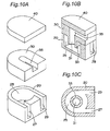
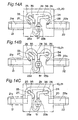
- the first guiding flow channel 27 and the intermediate flow channel 29 may be formed so as to be parallel to each other as shown in Fig. 10 . Alternatively, they may be formed so as to form an angle of less than 90° as shown in Fig. 11 . Further, as shown in Fig. 11 , the flow channel forming plate and the plate-like sealing member may be formed by integral molding. According to the present embodiment, there is an advantage of reducing the number of components and the number of assembling processes. Furthermore, it is a matter of course that the angle and size of the first and second guiding flow channels 27, 28 and the intermediate flow channel 29, and the diameters of the first and second flow dividing holes 31, 32 may be changed as required.
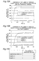
- the guiding flow channel extending from the secondary flow channel 22a to the inside of the centrifugal chamber 26 was arranged at an angle of 55° with respect to a flow direction of the secondary flow channel 22a, and the number of particles passing through the inside of the detection space portion 23b was calculated.
- Comparative Example 1 is almost the same as Example 1. A difference is that the guiding flow channel 28 was extended in a direction generally perpendicular to the secondary flow channel 22a and communicated with the centrifugal chamber 26. The calculation results are shown in Fig. 15A .
- Example 1 had fewer chances that dust and the like adhered to the detection element 51 compared with Comparative Example 1.
- each of the first and second guiding flow channels 27, 28 was inclined at an angle of 55° with respect to a flow direction of each of the first and second secondary flow channels 21a, 22a, and the intermediate flow channel 29 was formed straight, parallel to the first and second secondary flow channels 21a, 22a. Then, particles were put in under the same conditions as those of Example 1. The number of particles passing through the detection space portion 23b was calculated and the number of particles remaining in the flow channels was calculated. The calculation results are shown in Fig. 15B and Fig. 15C .
- Example 3 is almost the same as Example 2 described above. A difference is that the intermediate flow channel 29 was bent at an angle of 80° to form a generally V-shape. Then, particles were put in under the same conditions as those of Example 1. The number of particles passing through the detection space portion 23b was calculated and the number of particles remaining in the flow channels was calculated. The calculation results are shown in Fig. 15B and Fig. 15C .
- each of the first and second guiding flow channels 27, 28 was extended in a direction perpendicular to each of the first and second secondary flow channels 21a, 22a, and the intermediate flow channel 29 was formed straight, parallel to the first and second secondary flow channels 21a, 22a. Then, particles were put in under the same conditions as those of Example 1. The number of particles passing through the detection space portion 23b was calculated and the number of particles remaining in the flow channels was calculated. The calculation results are shown in Fig. 15B and Fig. 15C .
- the flow rate measuring device of the present invention may be not only connected to the primary flow pipe through the connection pipe but also connected to the primary flow pipe directly. Further, the flow rate measuring device may be used not only for flow rate measurement but also as a flow velocity measuring device.
Landscapes
- Physics & Mathematics (AREA)
- Fluid Mechanics (AREA)
- General Physics & Mathematics (AREA)
- Measuring Volume Flow (AREA)
Applications Claiming Priority (2)
| Application Number | Priority Date | Filing Date | Title |
|---|---|---|---|
| JP2005184672A JP3832498B1 (ja) | 2005-06-24 | 2005-06-24 | 流量測定装置 |
| PCT/JP2006/310560 WO2007000865A1 (fr) | 2005-06-24 | 2006-05-26 | Dispositif de mesure de débit |
Publications (3)
| Publication Number | Publication Date |
|---|---|
| EP1901042A1 true EP1901042A1 (fr) | 2008-03-19 |
| EP1901042A4 EP1901042A4 (fr) | 2008-12-17 |
| EP1901042B1 EP1901042B1 (fr) | 2010-10-13 |
Family
ID=37214358
Family Applications (1)
| Application Number | Title | Priority Date | Filing Date |
|---|---|---|---|
| EP06746889A Not-in-force EP1901042B1 (fr) | 2005-06-24 | 2006-05-26 | Dispositif de mesure de débit |
Country Status (8)
| Country | Link |
|---|---|
| US (1) | US7559256B2 (fr) |
| EP (1) | EP1901042B1 (fr) |
| JP (1) | JP3832498B1 (fr) |
| CN (1) | CN101248333B (fr) |
| AU (1) | AU2006263279B2 (fr) |
| BR (1) | BRPI0612526A2 (fr) |
| DE (1) | DE602006017549D1 (fr) |
| WO (1) | WO2007000865A1 (fr) |
Families Citing this family (11)
| Publication number | Priority date | Publication date | Assignee | Title |
|---|---|---|---|---|
| JP2008304396A (ja) * | 2007-06-08 | 2008-12-18 | Yamatake Corp | 流量計 |
| JP5003372B2 (ja) * | 2007-09-13 | 2012-08-15 | オムロン株式会社 | 流量測定装置 |
| JP2012026931A (ja) * | 2010-07-26 | 2012-02-09 | Omron Corp | 流量測定用構造体、および流量測定装置 |
| EP2663842B1 (fr) * | 2011-01-11 | 2019-03-13 | Inputive Corporation | Modèle de capteur mems/moems |
| JP5817598B2 (ja) | 2012-03-07 | 2015-11-18 | オムロン株式会社 | 流体測定装置 |
| CN108025130B (zh) * | 2015-08-28 | 2021-02-19 | 克里斯医疗系统股份有限公司 | 具有连接组件的流量传感器系统 |
| JP6355609B2 (ja) * | 2015-10-28 | 2018-07-11 | 日立オートモティブシステムズ株式会社 | 熱式流量計 |
| US10837812B2 (en) * | 2017-11-09 | 2020-11-17 | Honeywell International Inc | Miniature flow sensor with shroud |
| CN110455361A (zh) * | 2018-05-07 | 2019-11-15 | 中国石油化工股份有限公司 | 热式气体流量计及其应用 |
| CN117663013B (zh) * | 2023-12-04 | 2024-06-21 | 张腾 | 炉体水循环系统的漏水监测装置及方法 |
| US20250266641A1 (en) * | 2024-02-20 | 2025-08-21 | Shiver Nv | Power socket assembly and method of installing said assembly |
Family Cites Families (10)
| Publication number | Priority date | Publication date | Assignee | Title |
|---|---|---|---|---|
| SE227107C1 (fr) * | 1967-05-18 | 1969-07-29 | Alfa Laval Ab | |
| CN85204326U (zh) * | 1985-10-04 | 1986-08-27 | 段兆林 | 盲人手杖 |
| US4914947A (en) * | 1988-09-30 | 1990-04-10 | Honeywell Inc. | Sampling probe flow sensor |
| JP2841224B2 (ja) * | 1990-02-07 | 1998-12-24 | 株式会社堀場製作所 | 気液分離器 |
| JPH11166720A (ja) | 1997-12-04 | 1999-06-22 | Gastar Corp | ダストトラップ装置 |
| DE19815654A1 (de) * | 1998-04-08 | 1999-10-14 | Bosch Gmbh Robert | Meßvorrichtung zum Messen der Masse eines in einer Leitung strömenden Mediums |
| DE10019149B4 (de) | 2000-04-18 | 2007-06-06 | Robert Bosch Gmbh | Vorrichtung zur Bestimmung zumindest eines Parameters eines strömenden Mediums |
| JP3716163B2 (ja) * | 2000-06-16 | 2005-11-16 | 株式会社日立製作所 | 空気流量測定装置 |
| DE10246069A1 (de) * | 2002-10-02 | 2004-04-15 | Robert Bosch Gmbh | Vorrichtung zur Bestimmung wenigstens eines Parameters eines in einer Leitung strömenden Mediums |
| JP4534526B2 (ja) * | 2004-02-27 | 2010-09-01 | オムロン株式会社 | 流速測定装置 |
-
2005
- 2005-06-24 JP JP2005184672A patent/JP3832498B1/ja not_active Expired - Lifetime
-
2006
- 2006-05-26 WO PCT/JP2006/310560 patent/WO2007000865A1/fr not_active Ceased
- 2006-05-26 EP EP06746889A patent/EP1901042B1/fr not_active Not-in-force
- 2006-05-26 BR BRPI0612526-3A patent/BRPI0612526A2/pt active Search and Examination
- 2006-05-26 CN CN2006800226092A patent/CN101248333B/zh active Active
- 2006-05-26 US US11/993,803 patent/US7559256B2/en active Active
- 2006-05-26 DE DE602006017549T patent/DE602006017549D1/de active Active
- 2006-05-26 AU AU2006263279A patent/AU2006263279B2/en not_active Ceased
Also Published As
| Publication number | Publication date |
|---|---|
| BRPI0612526A2 (pt) | 2010-11-23 |
| AU2006263279B2 (en) | 2010-04-29 |
| DE602006017549D1 (de) | 2010-11-25 |
| US7559256B2 (en) | 2009-07-14 |
| CN101248333A (zh) | 2008-08-20 |
| EP1901042B1 (fr) | 2010-10-13 |
| CN101248333B (zh) | 2010-08-25 |
| JP2007003387A (ja) | 2007-01-11 |
| JP3832498B1 (ja) | 2006-10-11 |
| US20080314140A1 (en) | 2008-12-25 |
| WO2007000865A1 (fr) | 2007-01-04 |
| EP1901042A4 (fr) | 2008-12-17 |
| AU2006263279A1 (en) | 2007-01-04 |
Similar Documents
| Publication | Publication Date | Title |
|---|---|---|
| EP1901042B1 (fr) | Dispositif de mesure de débit | |
| CN100526812C (zh) | 流量传感器 | |
| CN106716078B (zh) | 用于确定流过测量通道的流体介质的至少一个参数的传感器组件 | |
| US9671269B2 (en) | Gas meter and particle trap | |
| JP4259522B2 (ja) | 流量測定装置 | |
| KR100702817B1 (ko) | 도관 내에서 유동하는 매질의 하나 이상의 파라미터를 측정하기 위한 측정 장치 | |
| CN100381824C (zh) | 流速测定装置 | |
| KR20050067407A (ko) | 라인 내의 유동 매질의 적어도 하나의 파라미터 검출 장치 | |
| KR101326189B1 (ko) | 평균피토관 타입의 유량측정장치 | |
| JP6650831B2 (ja) | ガス流路構造および流量センサ | |
| US8707806B2 (en) | Sampling and monitoring of particulate suspension material | |
| JP5003372B2 (ja) | 流量測定装置 | |
| US9322733B2 (en) | Duct port for pressure sensing | |
| KR20130003535A (ko) | 필터장치 | |
| JP2023085562A (ja) | ガス給排アダプタ及びガス検出装置 | |
| JP2003344133A (ja) | 流量計 | |
| JP2008051562A (ja) | 流体計測装置 | |
| CN115884830A (zh) | 具有布置在入口腔室内并与其流体连通的出口腔室的用于流体的颗粒分离器 | |
| JP2009002443A (ja) | 流体の配管構造 | |
| JPH11295117A (ja) | 流体振動形流量計 |
Legal Events
| Date | Code | Title | Description |
|---|---|---|---|
| PUAI | Public reference made under article 153(3) epc to a published international application that has entered the european phase |
Free format text: ORIGINAL CODE: 0009012 |
|
| 17P | Request for examination filed |
Effective date: 20080121 |
|
| AK | Designated contracting states |
Kind code of ref document: A1 Designated state(s): DE FR GB IT SE |
|
| DAX | Request for extension of the european patent (deleted) | ||
| RBV | Designated contracting states (corrected) |
Designated state(s): DE FR GB IT SE |
|
| A4 | Supplementary search report drawn up and despatched |
Effective date: 20081119 |
|
| 17Q | First examination report despatched |
Effective date: 20090227 |
|
| GRAP | Despatch of communication of intention to grant a patent |
Free format text: ORIGINAL CODE: EPIDOSNIGR1 |
|
| GRAS | Grant fee paid |
Free format text: ORIGINAL CODE: EPIDOSNIGR3 |
|
| GRAA | (expected) grant |
Free format text: ORIGINAL CODE: 0009210 |
|
| AK | Designated contracting states |
Kind code of ref document: B1 Designated state(s): DE FR GB IT SE |
|
| REG | Reference to a national code |
Ref country code: GB Ref legal event code: FG4D |
|
| REF | Corresponds to: |
Ref document number: 602006017549 Country of ref document: DE Date of ref document: 20101125 Kind code of ref document: P |
|
| PG25 | Lapsed in a contracting state [announced via postgrant information from national office to epo] |
Ref country code: SE Free format text: LAPSE BECAUSE OF FAILURE TO SUBMIT A TRANSLATION OF THE DESCRIPTION OR TO PAY THE FEE WITHIN THE PRESCRIBED TIME-LIMIT Effective date: 20101013 |
|
| PLBE | No opposition filed within time limit |
Free format text: ORIGINAL CODE: 0009261 |
|
| STAA | Information on the status of an ep patent application or granted ep patent |
Free format text: STATUS: NO OPPOSITION FILED WITHIN TIME LIMIT |
|
| 26N | No opposition filed |
Effective date: 20110714 |
|
| REG | Reference to a national code |
Ref country code: DE Ref legal event code: R097 Ref document number: 602006017549 Country of ref document: DE Effective date: 20110714 |
|
| PGFP | Annual fee paid to national office [announced via postgrant information from national office to epo] |
Ref country code: GB Payment date: 20140521 Year of fee payment: 9 |
|
| PGFP | Annual fee paid to national office [announced via postgrant information from national office to epo] |
Ref country code: FR Payment date: 20140509 Year of fee payment: 9 |
|
| GBPC | Gb: european patent ceased through non-payment of renewal fee |
Effective date: 20150526 |
|
| REG | Reference to a national code |
Ref country code: FR Ref legal event code: ST Effective date: 20160129 |
|
| PG25 | Lapsed in a contracting state [announced via postgrant information from national office to epo] |
Ref country code: GB Free format text: LAPSE BECAUSE OF NON-PAYMENT OF DUE FEES Effective date: 20150526 |
|
| PG25 | Lapsed in a contracting state [announced via postgrant information from national office to epo] |
Ref country code: FR Free format text: LAPSE BECAUSE OF NON-PAYMENT OF DUE FEES Effective date: 20150601 |
|
| REG | Reference to a national code |
Ref country code: DE Ref legal event code: R082 Ref document number: 602006017549 Country of ref document: DE Representative=s name: DOMPATENT VON KREISLER SELTING WERNER - PARTNE, DE Ref country code: DE Ref legal event code: R082 Ref document number: 602006017549 Country of ref document: DE Representative=s name: JOSTARNDT PATENTANWALTS-AG, DE |
|
| REG | Reference to a national code |
Ref country code: DE Ref legal event code: R082 Ref document number: 602006017549 Country of ref document: DE Representative=s name: DOMPATENT VON KREISLER SELTING WERNER - PARTNE, DE |
|
| PGFP | Annual fee paid to national office [announced via postgrant information from national office to epo] |
Ref country code: DE Payment date: 20240517 Year of fee payment: 19 |
|
| PGFP | Annual fee paid to national office [announced via postgrant information from national office to epo] |
Ref country code: IT Payment date: 20240531 Year of fee payment: 19 |
|
| REG | Reference to a national code |
Ref country code: DE Ref legal event code: R119 Ref document number: 602006017549 Country of ref document: DE |
|
| PG25 | Lapsed in a contracting state [announced via postgrant information from national office to epo] |
Ref country code: DE Free format text: LAPSE BECAUSE OF NON-PAYMENT OF DUE FEES Effective date: 20251202 |
|
| PG25 | Lapsed in a contracting state [announced via postgrant information from national office to epo] |
Ref country code: IT Free format text: LAPSE BECAUSE OF NON-PAYMENT OF DUE FEES Effective date: 20250526 |