EP1901148A2 - Système d'affichage destiné à la représentation graphique de signaux d'alarmes d'une installation technique ou d'un processus technique - Google Patents
Système d'affichage destiné à la représentation graphique de signaux d'alarmes d'une installation technique ou d'un processus technique Download PDFInfo
- Publication number
- EP1901148A2 EP1901148A2 EP07014774A EP07014774A EP1901148A2 EP 1901148 A2 EP1901148 A2 EP 1901148A2 EP 07014774 A EP07014774 A EP 07014774A EP 07014774 A EP07014774 A EP 07014774A EP 1901148 A2 EP1901148 A2 EP 1901148A2
- Authority
- EP
- European Patent Office
- Prior art keywords
- display unit
- mass
- alarm display
- areas
- measuring points
- Prior art date
- Legal status (The legal status is an assumption and is not a legal conclusion. Google has not performed a legal analysis and makes no representation as to the accuracy of the status listed.)
- Granted
Links
Images


Classifications
-
- G—PHYSICS
- G05—CONTROLLING; REGULATING
- G05B—CONTROL OR REGULATING SYSTEMS IN GENERAL; FUNCTIONAL ELEMENTS OF SUCH SYSTEMS; MONITORING OR TESTING ARRANGEMENTS FOR SUCH SYSTEMS OR ELEMENTS
- G05B23/00—Testing or monitoring of control systems or parts thereof
- G05B23/02—Electric testing or monitoring
- G05B23/0205—Electric testing or monitoring by means of a monitoring system capable of detecting and responding to faults
- G05B23/0259—Electric testing or monitoring by means of a monitoring system capable of detecting and responding to faults characterized by the response to fault detection
- G05B23/0267—Fault communication, e.g. human machine interface [HMI]
- G05B23/0272—Presentation of monitored results, e.g. selection of status reports to be displayed; Filtering information to the user
Definitions
- the invention relates to a display system and a method for the graphical representation of alarm messages from measured values of a technical system or a technical process, in particular in power plants or oil refineries, according to claims 1 and 6 and is particularly suitable for the graphical representation of process alarms.
- alarm messages which indicate, for example, critical process states
- the alarm messages are usually displayed with a plurality of display elements, which are usually assigned directly to the corresponding measured values
- the measured process values are usually characterized systematically according to task, type and location, for example by means of the power plant identification system "KKS" which is common in power plants worldwide.
- a mass alarm display graphically, for example, a plurality of display elements is arranged so that their overall image can be used by the plant operator for a pattern recognition.
- each individual display element must be separately configured, normalized and arranged according to the plant topology in the mass alarm display, so that the mass alarm display generates specific in the event of disturbances in the system.
- This form of representation of the mass alarm display is associated with a considerable planning effort, since each measured value is to be wired individually.
- the US 2005216826 describes a method with which the complex relationships in the presentation of mass alarms can be visualized without much configuration effort.
- the method described is used to analyze process relationships. However, process states can not be represented.
- the invention is accordingly based on the object of specifying a display system and a method for the graphic display of alarm messages from measured values of a technical installation or a technical process, in particular for displaying process alarms, whereby the aforementioned disadvantages of the prior art are overcome.
- the display system for the graphic display of alarm messages from measured values of a technical installation or a technical process comprises a processing device in which hierarchically structured markings measuring points of the measured values are stored.
- the processing device decomposes the hierarchically structured markings of the measuring points in hierarchical levels of different valence, selects the marking of the hierarchy level of the respective measuring point with the highest significance and transmits the selected markings of the respective measuring point of a preconfigured mass alarm display unit, the selected markings an appropriately marked area within a Overview image of the system or the process of preconfigured mass alarm display unit can be assigned and the alarm messages generated from the measured values, taking into account the generated assignment of the selected markings of the respective measuring point to marked accordingly Area within the overview screen of the system or process are graphically displayed.
- the mass alarm display unit of the display system according to the invention is preferably designed to display a plurality of process alarms, also referred to as mass alarms, and to generate an overall image when multiple alarms are linked together via the process dynamics.
- the mass alarm display unit is preconfigured such that a system image displayed by means of the mass alarm display unit is divided into areas, wherein these areas may also overlap one another.
- Each of these areas is assigned a master key, for example a KKS main group, and determines with which visual effects the areas of the plant picture should visualize the pending process statuses.
- KKS main group determines with which visual effects the areas of the plant picture should visualize the pending process statuses.
- various effects of modern computer graphics are suitable, such as coloring a black and white image, the representation of the areas by blurring, a lightening or darkening of the corresponding areas or a morphing (computer-generated special effect, for example between two frames, intermediate transitions are calculated and displayed as a seamless transition) of bitmaps.
- the regions in a plant image in which many temperature alarms occur are graphically deposited in such a way that these regions can be represented by a so-called "melting".
- Another advantage of the system according to the invention is based on the fact that the project-specific configuration effort during the planning phase of the system is greatly reduced or completely eliminated.
- the claim 6 can be seen.
- the measuring points of the measured values of the technical installation or of the technical process are given a hierarchically structured identification assigned and the hierarchically structured markings of the measuring points are stored in a processing device.
- the hierarchically structured identifications of the measuring points are in each case divided into hierarchical levels of different valence in a first step.
- the marking of the hierarchy level of the respective measuring point with the highest significance is selected and the selected markings of the measuring points are transmitted to a preconfigured mass alarm display unit.
- the selected and transmitted to the preconfigured mass alarm display unit markings are each assigned in a correspondingly marked area within an overview image of the plant or the process of preconfigured mass alarm display unit in a subsequent step and the alarms generated from the measured values are in a final step, taking into account the generated assignment of the selected Markings of the measuring points for the correspondingly marked area are graphically represented within the overview image of the plant or of the process, so that a process state-driven dynamically generated visually demanding computer graphics is shown on the mass alarm display unit.
- the system and method according to the invention are preferably used in power plants or oil refineries and are particularly suitable for the representation of process alarms.
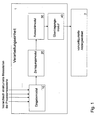
- FIG. 1 shows an embodiment of the display system according to the invention for the graphical representation of alarm messages from measured values of a power plant, the measuring points of the measured values each having a hierarchically structured identification.
- the display system for the graphic display of alarm messages from the power plant includes a processing device 1 and a preconfigured mass alarm display unit 2.
- the preconfigured mass alarm display unit 2 represents a plant overview image of the power plant, for example the water-steam cycle.
- the overview image is divided into individual areas, such as the turbine area, the feed water area, the condensate system, the area of the reheaters and the area of the preheater.
- the areas of the overview image are preconfigured to the effect that each area is assigned a unique identifier according to the KKS system.
- An exemplary plant overview image is shown in FIG. 3.
- the measuring points of the measured values are each provided with a unique hierarchically structured identification according to the KKS system, which can be transferred to an input module 10 of the processing device 1.
- the input module 10 cooperates with a decomposition module 20, which decomposes the hierarchically structured markings of the measuring points in hierarchy levels of different valence and feeds them to a selection module 30.
- the selection module 30 selects the marking of the hierarchy level of the respective measuring point with the highest significance and transmits the selected identifications of the measuring points to the preconfigured mass alarm display unit 2 by means of a transmission module 40.
- the mass alarm display unit 2 assigns the selected flags to the corresponding area code of the respective area within the plant outline image of the preconfigured mass alarm display unit 2.
- An identification of the measuring point with the highest significance is based in the invention described above, for example on the KKS label for the level in the feedwater tank.
- the alarm messages generated from the measured values can now be displayed graphically, taking into account the generated assignment of the selected markings of the measuring points to the correspondingly marked area within the overview image of the plant or the process, and the measured value in the corresponding area of the overview image can be visually changed, for example colored or blurred, if an alarm message is pending for the respective measured value.
- FIG. 2 an exemplary process flow for the graphical representation of the mass alarms of the power plant is shown.
- the method according to the invention describes a number of steps with which the graphical representation of the alarm messages is executed by means of the alarm system according to the invention.
- a first step 100 the hierarchically structured markings of the measuring points of the system are transmitted to the processing device 1, and in a second step 200, the hierarchically structured markings of the measuring points are broken down into hierarchical levels with different significance.
- the selected markings measuring points of the preconfigured mass alarm display unit 2 are transmitted in a fourth step 500.
- a further step 500 the selected and transmitted to the preconfigured mass alarm display unit 2 markings associated with a correspondingly marked area within an overview image of the system of preconfigured mass alarm display unit 2.
- the alarm messages generated from the measured values are visualized, for example colored, in a last step 600 taking into account the generated assignment of the selected markings of the measuring points to the correspondingly marked area within the overview image according to their relevance for the functioning of the system with a corresponding computer graphics effect.
- An embodiment of the method according to the invention is based on the fact that the overall picture of the system is represented on the mass alarm display unit 2 as a bitmap, which is usually a drawing or a photo of the installation, which is shown in FIG. 3 as a plant overview image, wherein the bitmap divided into a plurality of areas H, M, P, the areas are each treated separately and can overlap each other.
- Each of these areas H, M, P is assigned a particular identifier, for example a KKS main group, which is valid for a large number of installations. This advantageously results in the possibility of delivering preconfigured displays which no longer require a project-specific adaptation.
- a computer-aided image processing method is used, which is based on a parameterizable graphic transformation.
- this graphic transformation known as morphing
- a bitmap 1 is blended into another bitmap 2 by calculating intermediate transitions between two individual images, the bitmap 1 and the bitmap 2, and representing these as seamless transitions.
- the intermediate levels between Bitmap 1 and Bitmap 2 are determined by the following formula: x * bitmap2 + (1-x) * Bitmap1 with 0 ⁇ x> 1.
- the mapping rules include, for example, the number of alarms per time interval in the corresponding main group, the number of manual interventions per time interval or the priority of the currently pending alarm with the highest priority.
- the color photo of the plant or the plant part is shown.
- the sum of the priorities of the alarms active in one area is used as a weighting for the functioning of the system. For example, if the sum of the priorities of the active alarms is 0, the color photo is shown, is the sum of the priorities of the active alarms 100 is the black and white photo shown, and is the sum of the priorities of the active alarms between 0 and 100 becomes a correspondingly morphed image shown from both photos.
- the previously described visualization of the system can also be used to display a corresponding section of the overall system.
Landscapes
- Engineering & Computer Science (AREA)
- Human Computer Interaction (AREA)
- Physics & Mathematics (AREA)
- General Physics & Mathematics (AREA)
- Automation & Control Theory (AREA)
- Testing And Monitoring For Control Systems (AREA)
- User Interface Of Digital Computer (AREA)
- Alarm Systems (AREA)
Priority Applications (1)
| Application Number | Priority Date | Filing Date | Title |
|---|---|---|---|
| PL07014774T PL1901148T3 (pl) | 2006-09-16 | 2007-07-27 | System wyświetlania do graficznego przedstawiania komunikatów alarmowych instalacji technicznej lub procesu technicznego |
Applications Claiming Priority (1)
| Application Number | Priority Date | Filing Date | Title |
|---|---|---|---|
| DE102006043579A DE102006043579A1 (de) | 2006-09-16 | 2006-09-16 | Anzeigesystem zur grafischen Darstellung von Alarmmeldungen einer technischen Anlage oder eines technischen Prozesses |
Publications (3)
| Publication Number | Publication Date |
|---|---|
| EP1901148A2 true EP1901148A2 (fr) | 2008-03-19 |
| EP1901148A3 EP1901148A3 (fr) | 2009-12-30 |
| EP1901148B1 EP1901148B1 (fr) | 2012-12-19 |
Family
ID=38802470
Family Applications (1)
| Application Number | Title | Priority Date | Filing Date |
|---|---|---|---|
| EP07014774A Active EP1901148B1 (fr) | 2006-09-16 | 2007-07-27 | Système d'affichage destiné à la représentation graphique de signaux d'alarmes d'une installation technique ou d'un processus technique |
Country Status (7)
| Country | Link |
|---|---|
| US (1) | US9235209B2 (fr) |
| EP (1) | EP1901148B1 (fr) |
| CN (1) | CN101145056B (fr) |
| DE (1) | DE102006043579A1 (fr) |
| DK (1) | DK1901148T3 (fr) |
| ES (1) | ES2400521T3 (fr) |
| PL (1) | PL1901148T3 (fr) |
Families Citing this family (4)
| Publication number | Priority date | Publication date | Assignee | Title |
|---|---|---|---|---|
| PL2458467T3 (pl) * | 2010-11-26 | 2014-03-31 | Abb Research Ltd | Sposób i system do monitorowania systemu przemysłowego |
| DE102012220639A1 (de) | 2012-11-13 | 2014-05-15 | Siemens Aktiengesellschaft | Benutzerschnittstelle und Verfahren zur Behebung von Störungen einer industriellen Anlage |
| US9007207B2 (en) * | 2013-01-22 | 2015-04-14 | General Electric Company | Dynamic alarm system for operating a power plant and method of responding to same |
| CN103941716B (zh) * | 2014-05-13 | 2016-08-31 | 北京世纪微熵科技股份有限公司 | 建筑设备监控方法、装置和系统 |
Citations (2)
| Publication number | Priority date | Publication date | Assignee | Title |
|---|---|---|---|---|
| EP0482523A2 (fr) | 1990-10-24 | 1992-04-29 | Osaka Gas Co., Ltd. | Interface opérateur polyvalente pour afficher les résultats de diagnostic de faute dans un système de commande de processus intelligent |
| US20050216826A1 (en) | 2005-05-09 | 2005-09-29 | Matrikon Inc. | Method of providing a concurrent overview and detailed display of industrial production facilities |
Family Cites Families (10)
| Publication number | Priority date | Publication date | Assignee | Title |
|---|---|---|---|---|
| JP2907858B2 (ja) * | 1989-03-20 | 1999-06-21 | 株式会社日立製作所 | 表示装置および方法 |
| US5963884A (en) * | 1996-09-23 | 1999-10-05 | Machine Xpert, Llc | Predictive maintenance system |
| US7206646B2 (en) * | 1999-02-22 | 2007-04-17 | Fisher-Rosemount Systems, Inc. | Method and apparatus for performing a function in a plant using process performance monitoring with process equipment monitoring and control |
| US8044793B2 (en) * | 2001-03-01 | 2011-10-25 | Fisher-Rosemount Systems, Inc. | Integrated device alerts in a process control system |
| US6421571B1 (en) * | 2000-02-29 | 2002-07-16 | Bently Nevada Corporation | Industrial plant asset management system: apparatus and method |
| FI20001340L (fi) * | 2000-06-05 | 2002-01-28 | Metso Automation Networks Oy | Menetelmõ prosessinohjausjõrjestelmõssõ ja prosessinohjausjõrjestelmõ |
| US7389204B2 (en) * | 2001-03-01 | 2008-06-17 | Fisher-Rosemount Systems, Inc. | Data presentation system for abnormal situation prevention in a process plant |
| JP2007536634A (ja) * | 2004-05-04 | 2007-12-13 | フィッシャー−ローズマウント・システムズ・インコーポレーテッド | プロセス制御システムのためのサービス指向型アーキテクチャ |
| CN1288453C (zh) * | 2004-12-08 | 2006-12-06 | 中国海洋大学 | 海上气象能见度的卫星定量遥感方法 |
| US7729887B2 (en) * | 2006-04-11 | 2010-06-01 | Invensys Systems, Inc. | System management user interface providing user access to status information for process control system equipment including a status monitor |
-
2006
- 2006-09-16 DE DE102006043579A patent/DE102006043579A1/de not_active Withdrawn
-
2007
- 2007-07-27 ES ES07014774T patent/ES2400521T3/es active Active
- 2007-07-27 PL PL07014774T patent/PL1901148T3/pl unknown
- 2007-07-27 EP EP07014774A patent/EP1901148B1/fr active Active
- 2007-07-27 DK DK07014774.9T patent/DK1901148T3/da active
- 2007-08-24 US US11/844,687 patent/US9235209B2/en active Active
- 2007-09-14 CN CN2007101536853A patent/CN101145056B/zh active Active
Patent Citations (2)
| Publication number | Priority date | Publication date | Assignee | Title |
|---|---|---|---|---|
| EP0482523A2 (fr) | 1990-10-24 | 1992-04-29 | Osaka Gas Co., Ltd. | Interface opérateur polyvalente pour afficher les résultats de diagnostic de faute dans un système de commande de processus intelligent |
| US20050216826A1 (en) | 2005-05-09 | 2005-09-29 | Matrikon Inc. | Method of providing a concurrent overview and detailed display of industrial production facilities |
Also Published As
| Publication number | Publication date |
|---|---|
| EP1901148A3 (fr) | 2009-12-30 |
| US9235209B2 (en) | 2016-01-12 |
| ES2400521T3 (es) | 2013-04-10 |
| CN101145056A (zh) | 2008-03-19 |
| US20080072171A1 (en) | 2008-03-20 |
| EP1901148B1 (fr) | 2012-12-19 |
| DE102006043579A1 (de) | 2008-04-03 |
| CN101145056B (zh) | 2012-09-05 |
| PL1901148T3 (pl) | 2013-05-31 |
| DK1901148T3 (da) | 2013-04-02 |
Similar Documents
| Publication | Publication Date | Title |
|---|---|---|
| EP3953774B1 (fr) | Dispositif pour la détection de causes d'alarmes | |
| EP2455855A1 (fr) | Affichage comparatif graphique de logiciels | |
| DE102009021062A1 (de) | Alarmverwaltungssystem | |
| EP1901148B1 (fr) | Système d'affichage destiné à la représentation graphique de signaux d'alarmes d'une installation technique ou d'un processus technique | |
| EP2833349A1 (fr) | Procédé et dispositif de représentation d'un état relevant de la sécurité | |
| DE102016123235A1 (de) | Betriebsverwaltungssystem zum direkten anzeigen eines arbeitsbefehls auf basis einer betriebsverwaltungsinformation an einer werkzeugmaschine | |
| EP3680740A1 (fr) | Affichages de journaux d'alarme | |
| WO2003038538A1 (fr) | Systeme et procede pour representer de façon dynamique l'etat actuel d'une tache en relation avec un etat cible | |
| EP3637211B1 (fr) | Procédé de fonctionnement d'une installation ainsi qu'une installation | |
| DE19637651A1 (de) | Verfahren zur Prozeßvisualisierung | |
| DE102020119853B3 (de) | Verfahren zum Steuern eines Automatisierungssystems mit Visualisierung von Programmobjekten eines Steuerprogramms des Automatisierungssystems und Automatisierungssystem | |
| EP4030247B1 (fr) | Annotation de retour des réductions de charge des clients | |
| EP1655663A1 (fr) | Modélisation d'un flux de données dans les systèmes d'ingénierie | |
| EP2560085A1 (fr) | Procédé de configuration d'un dispositif d'affichage pour l'affichage de signalisations d'alerte dynamiques d'un système de commande et de surveillance d'une installation d'automatisation technique | |
| EP4261629A1 (fr) | Système de commande pour une installation technique et procédé de fonctionnement | |
| DE102006010500B4 (de) | Konfigurationseinrichtung zum Erzeugen von Informationen zur Modernisierung einer Anlage | |
| DE10208251A1 (de) | Verfahren und Einrichtung zur Überwachung von Prozessen in einer bahnverarbeitenden Druckmaschine | |
| EP3701341B1 (fr) | Procédé de traitement assisté par ordinateur de paramètres de fonctionnement d'un système technique | |
| EP2386920A1 (fr) | Procédé d'évaluation d'alertes de diagnostic | |
| EP2490086A1 (fr) | Procédé de fonctionnement de systèmes d'automatisation et programme informatique fonctionnant selon ce procédé | |
| EP4666139A1 (fr) | Fragments d'image d'installation pour faire fonctionner et observer une installation | |
| WO2025003185A1 (fr) | Système de commande de coordination des opérateurs pour une installation technique et procédé de fonctionnement | |
| DE102019135520A1 (de) | Verfahren und Vorrichtung zum Überprüfen von Parametereinstellungen eines Steuergeräts eines Fahrzeugs | |
| EP4354233A1 (fr) | Système de guidage pour une installation technique et procédé de fonctionnement | |
| EP4290326A1 (fr) | Système de commande pour une installation technique et procédé de fonctionnement |
Legal Events
| Date | Code | Title | Description |
|---|---|---|---|
| PUAI | Public reference made under article 153(3) epc to a published international application that has entered the european phase |
Free format text: ORIGINAL CODE: 0009012 |
|
| AK | Designated contracting states |
Kind code of ref document: A2 Designated state(s): AT BE BG CH CY CZ DE DK EE ES FI FR GB GR HU IE IS IT LI LT LU LV MC MT NL PL PT RO SE SI SK TR |
|
| AX | Request for extension of the european patent |
Extension state: AL BA HR MK YU |
|
| PUAL | Search report despatched |
Free format text: ORIGINAL CODE: 0009013 |
|
| AK | Designated contracting states |
Kind code of ref document: A3 Designated state(s): AT BE BG CH CY CZ DE DK EE ES FI FR GB GR HU IE IS IT LI LT LU LV MC MT NL PL PT RO SE SI SK TR |
|
| AX | Request for extension of the european patent |
Extension state: AL BA HR MK RS |
|
| 17P | Request for examination filed |
Effective date: 20100630 |
|
| 17Q | First examination report despatched |
Effective date: 20100728 |
|
| AKX | Designation fees paid |
Designated state(s): AT BE BG CH CY CZ DE DK EE ES FI FR GB GR HU IE IS IT LI LT LU LV MC MT NL PL PT RO SE SI SK TR |
|
| REG | Reference to a national code |
Ref country code: DE Ref legal event code: R079 Ref document number: 502007011051 Country of ref document: DE Free format text: PREVIOUS MAIN CLASS: G05B0019048000 Ipc: G05B0023020000 |
|
| GRAP | Despatch of communication of intention to grant a patent |
Free format text: ORIGINAL CODE: EPIDOSNIGR1 |
|
| RIC1 | Information provided on ipc code assigned before grant |
Ipc: G05B 23/02 20060101AFI20120817BHEP Ipc: G05B 19/048 20060101ALI20120817BHEP |
|
| GRAS | Grant fee paid |
Free format text: ORIGINAL CODE: EPIDOSNIGR3 |
|
| GRAA | (expected) grant |
Free format text: ORIGINAL CODE: 0009210 |
|
| AK | Designated contracting states |
Kind code of ref document: B1 Designated state(s): AT BE BG CH CY CZ DE DK EE ES FI FR GB GR HU IE IS IT LI LT LU LV MC MT NL PL PT RO SE SI SK TR |
|
| REG | Reference to a national code |
Ref country code: GB Ref legal event code: FG4D Free format text: NOT ENGLISH |
|
| REG | Reference to a national code |
Ref country code: CH Ref legal event code: EP |
|
| REG | Reference to a national code |
Ref country code: AT Ref legal event code: REF Ref document number: 589682 Country of ref document: AT Kind code of ref document: T Effective date: 20130115 |
|
| REG | Reference to a national code |
Ref country code: DE Ref legal event code: R096 Ref document number: 502007011051 Country of ref document: DE Effective date: 20130221 |
|
| REG | Reference to a national code |
Ref country code: SE Ref legal event code: TRGR Ref country code: DK Ref legal event code: T3 |
|
| REG | Reference to a national code |
Ref country code: ES Ref legal event code: FG2A Ref document number: 2400521 Country of ref document: ES Kind code of ref document: T3 Effective date: 20130410 |
|
| PG25 | Lapsed in a contracting state [announced via postgrant information from national office to epo] |
Ref country code: FI Free format text: LAPSE BECAUSE OF FAILURE TO SUBMIT A TRANSLATION OF THE DESCRIPTION OR TO PAY THE FEE WITHIN THE PRESCRIBED TIME-LIMIT Effective date: 20121219 Ref country code: LT Free format text: LAPSE BECAUSE OF FAILURE TO SUBMIT A TRANSLATION OF THE DESCRIPTION OR TO PAY THE FEE WITHIN THE PRESCRIBED TIME-LIMIT Effective date: 20121219 |
|
| REG | Reference to a national code |
Ref country code: NL Ref legal event code: T3 |
|
| REG | Reference to a national code |
Ref country code: LT Ref legal event code: MG4D |
|
| PG25 | Lapsed in a contracting state [announced via postgrant information from national office to epo] |
Ref country code: SI Free format text: LAPSE BECAUSE OF FAILURE TO SUBMIT A TRANSLATION OF THE DESCRIPTION OR TO PAY THE FEE WITHIN THE PRESCRIBED TIME-LIMIT Effective date: 20121219 Ref country code: GR Free format text: LAPSE BECAUSE OF FAILURE TO SUBMIT A TRANSLATION OF THE DESCRIPTION OR TO PAY THE FEE WITHIN THE PRESCRIBED TIME-LIMIT Effective date: 20130320 Ref country code: LV Free format text: LAPSE BECAUSE OF FAILURE TO SUBMIT A TRANSLATION OF THE DESCRIPTION OR TO PAY THE FEE WITHIN THE PRESCRIBED TIME-LIMIT Effective date: 20121219 |
|
| REG | Reference to a national code |
Ref country code: PL Ref legal event code: T3 |
|
| PG25 | Lapsed in a contracting state [announced via postgrant information from national office to epo] |
Ref country code: SK Free format text: LAPSE BECAUSE OF FAILURE TO SUBMIT A TRANSLATION OF THE DESCRIPTION OR TO PAY THE FEE WITHIN THE PRESCRIBED TIME-LIMIT Effective date: 20121219 Ref country code: BG Free format text: LAPSE BECAUSE OF FAILURE TO SUBMIT A TRANSLATION OF THE DESCRIPTION OR TO PAY THE FEE WITHIN THE PRESCRIBED TIME-LIMIT Effective date: 20130319 Ref country code: EE Free format text: LAPSE BECAUSE OF FAILURE TO SUBMIT A TRANSLATION OF THE DESCRIPTION OR TO PAY THE FEE WITHIN THE PRESCRIBED TIME-LIMIT Effective date: 20121219 Ref country code: IS Free format text: LAPSE BECAUSE OF FAILURE TO SUBMIT A TRANSLATION OF THE DESCRIPTION OR TO PAY THE FEE WITHIN THE PRESCRIBED TIME-LIMIT Effective date: 20130419 |
|
| PG25 | Lapsed in a contracting state [announced via postgrant information from national office to epo] |
Ref country code: PT Free format text: LAPSE BECAUSE OF FAILURE TO SUBMIT A TRANSLATION OF THE DESCRIPTION OR TO PAY THE FEE WITHIN THE PRESCRIBED TIME-LIMIT Effective date: 20130419 Ref country code: RO Free format text: LAPSE BECAUSE OF FAILURE TO SUBMIT A TRANSLATION OF THE DESCRIPTION OR TO PAY THE FEE WITHIN THE PRESCRIBED TIME-LIMIT Effective date: 20121219 |
|
| PLBE | No opposition filed within time limit |
Free format text: ORIGINAL CODE: 0009261 |
|
| STAA | Information on the status of an ep patent application or granted ep patent |
Free format text: STATUS: NO OPPOSITION FILED WITHIN TIME LIMIT |
|
| 26N | No opposition filed |
Effective date: 20130920 |
|
| PG25 | Lapsed in a contracting state [announced via postgrant information from national office to epo] |
Ref country code: CY Free format text: LAPSE BECAUSE OF FAILURE TO SUBMIT A TRANSLATION OF THE DESCRIPTION OR TO PAY THE FEE WITHIN THE PRESCRIBED TIME-LIMIT Effective date: 20121219 |
|
| REG | Reference to a national code |
Ref country code: DE Ref legal event code: R097 Ref document number: 502007011051 Country of ref document: DE Effective date: 20130920 |
|
| BERE | Be: lapsed |
Owner name: ABB TECHNOLOGY A.G. Effective date: 20130731 |
|
| PG25 | Lapsed in a contracting state [announced via postgrant information from national office to epo] |
Ref country code: MC Free format text: LAPSE BECAUSE OF FAILURE TO SUBMIT A TRANSLATION OF THE DESCRIPTION OR TO PAY THE FEE WITHIN THE PRESCRIBED TIME-LIMIT Effective date: 20121219 |
|
| GBPC | Gb: european patent ceased through non-payment of renewal fee |
Effective date: 20130727 |
|
| REG | Reference to a national code |
Ref country code: IE Ref legal event code: MM4A |
|
| REG | Reference to a national code |
Ref country code: FR Ref legal event code: ST Effective date: 20140331 |
|
| PG25 | Lapsed in a contracting state [announced via postgrant information from national office to epo] |
Ref country code: GB Free format text: LAPSE BECAUSE OF NON-PAYMENT OF DUE FEES Effective date: 20130727 Ref country code: BE Free format text: LAPSE BECAUSE OF NON-PAYMENT OF DUE FEES Effective date: 20130731 |
|
| PG25 | Lapsed in a contracting state [announced via postgrant information from national office to epo] |
Ref country code: FR Free format text: LAPSE BECAUSE OF NON-PAYMENT OF DUE FEES Effective date: 20130731 |
|
| PG25 | Lapsed in a contracting state [announced via postgrant information from national office to epo] |
Ref country code: IE Free format text: LAPSE BECAUSE OF NON-PAYMENT OF DUE FEES Effective date: 20130727 |
|
| REG | Reference to a national code |
Ref country code: AT Ref legal event code: MM01 Ref document number: 589682 Country of ref document: AT Kind code of ref document: T Effective date: 20130727 |
|
| PG25 | Lapsed in a contracting state [announced via postgrant information from national office to epo] |
Ref country code: AT Free format text: LAPSE BECAUSE OF NON-PAYMENT OF DUE FEES Effective date: 20130727 |
|
| PG25 | Lapsed in a contracting state [announced via postgrant information from national office to epo] |
Ref country code: TR Free format text: LAPSE BECAUSE OF FAILURE TO SUBMIT A TRANSLATION OF THE DESCRIPTION OR TO PAY THE FEE WITHIN THE PRESCRIBED TIME-LIMIT Effective date: 20121219 Ref country code: MT Free format text: LAPSE BECAUSE OF FAILURE TO SUBMIT A TRANSLATION OF THE DESCRIPTION OR TO PAY THE FEE WITHIN THE PRESCRIBED TIME-LIMIT Effective date: 20121219 |
|
| PG25 | Lapsed in a contracting state [announced via postgrant information from national office to epo] |
Ref country code: HU Free format text: LAPSE BECAUSE OF FAILURE TO SUBMIT A TRANSLATION OF THE DESCRIPTION OR TO PAY THE FEE WITHIN THE PRESCRIBED TIME-LIMIT; INVALID AB INITIO Effective date: 20070727 Ref country code: LU Free format text: LAPSE BECAUSE OF NON-PAYMENT OF DUE FEES Effective date: 20130727 |
|
| REG | Reference to a national code |
Ref country code: DE Ref legal event code: R081 Ref document number: 502007011051 Country of ref document: DE Owner name: ABB SCHWEIZ AG, CH Free format text: FORMER OWNER: ABB TECHNOLOGY AG, ZUERICH, CH |
|
| REG | Reference to a national code |
Ref country code: ES Ref legal event code: PC2A Owner name: ABB SCHWEIZ AG Effective date: 20171218 |
|
| REG | Reference to a national code |
Ref country code: CH Ref legal event code: PFUS Owner name: ABB SCHWEIZ AG, CH Free format text: FORMER OWNER: ABB TECHNOLOGY AG, CH |
|
| REG | Reference to a national code |
Ref country code: NL Ref legal event code: PD Owner name: ABB SCHWEIZ AG; CH Free format text: DETAILS ASSIGNMENT: CHANGE OF OWNER(S), MERGE; FORMER OWNER NAME: ABB TECHNOLOGY AG Effective date: 20180115 |
|
| PGFP | Annual fee paid to national office [announced via postgrant information from national office to epo] |
Ref country code: NL Payment date: 20230719 Year of fee payment: 17 |
|
| PGFP | Annual fee paid to national office [announced via postgrant information from national office to epo] |
Ref country code: IT Payment date: 20230724 Year of fee payment: 17 Ref country code: ES Payment date: 20230926 Year of fee payment: 17 Ref country code: CZ Payment date: 20230717 Year of fee payment: 17 Ref country code: CH Payment date: 20230802 Year of fee payment: 17 |
|
| PGFP | Annual fee paid to national office [announced via postgrant information from national office to epo] |
Ref country code: SE Payment date: 20230719 Year of fee payment: 17 Ref country code: PL Payment date: 20230714 Year of fee payment: 17 Ref country code: DK Payment date: 20230721 Year of fee payment: 17 |
|
| REG | Reference to a national code |
Ref country code: DK Ref legal event code: EBP Effective date: 20240731 |
|
| REG | Reference to a national code |
Ref country code: CH Ref legal event code: PL |
|
| REG | Reference to a national code |
Ref country code: SE Ref legal event code: EUG |
|
| REG | Reference to a national code |
Ref country code: NL Ref legal event code: MM Effective date: 20240801 |
|
| PG25 | Lapsed in a contracting state [announced via postgrant information from national office to epo] |
Ref country code: NL Free format text: LAPSE BECAUSE OF NON-PAYMENT OF DUE FEES Effective date: 20240801 |
|
| PG25 | Lapsed in a contracting state [announced via postgrant information from national office to epo] |
Ref country code: CH Free format text: LAPSE BECAUSE OF NON-PAYMENT OF DUE FEES Effective date: 20240731 |
|
| PG25 | Lapsed in a contracting state [announced via postgrant information from national office to epo] |
Ref country code: CZ Free format text: LAPSE BECAUSE OF NON-PAYMENT OF DUE FEES Effective date: 20240727 |
|
| PG25 | Lapsed in a contracting state [announced via postgrant information from national office to epo] |
Ref country code: DK Free format text: LAPSE BECAUSE OF NON-PAYMENT OF DUE FEES Effective date: 20240731 |
|
| PG25 | Lapsed in a contracting state [announced via postgrant information from national office to epo] |
Ref country code: IT Free format text: LAPSE BECAUSE OF NON-PAYMENT OF DUE FEES Effective date: 20240727 |
|
| REG | Reference to a national code |
Ref country code: ES Ref legal event code: FD2A Effective date: 20250829 |
|
| PG25 | Lapsed in a contracting state [announced via postgrant information from national office to epo] |
Ref country code: ES Free format text: LAPSE BECAUSE OF NON-PAYMENT OF DUE FEES Effective date: 20240728 |
|
| PGFP | Annual fee paid to national office [announced via postgrant information from national office to epo] |
Ref country code: DE Payment date: 20250722 Year of fee payment: 19 |
|
| PG25 | Lapsed in a contracting state [announced via postgrant information from national office to epo] |
Ref country code: SE Free format text: LAPSE BECAUSE OF NON-PAYMENT OF DUE FEES Effective date: 20240728 |
|
| PG25 | Lapsed in a contracting state [announced via postgrant information from national office to epo] |
Ref country code: PL Free format text: LAPSE BECAUSE OF NON-PAYMENT OF DUE FEES Effective date: 20240727 |