EP1901377A1 - Eine Elektrode - Google Patents
Eine Elektrode Download PDFInfo
- Publication number
- EP1901377A1 EP1901377A1 EP06254561A EP06254561A EP1901377A1 EP 1901377 A1 EP1901377 A1 EP 1901377A1 EP 06254561 A EP06254561 A EP 06254561A EP 06254561 A EP06254561 A EP 06254561A EP 1901377 A1 EP1901377 A1 EP 1901377A1
- Authority
- EP
- European Patent Office
- Prior art keywords
- electrode
- terminals
- radius
- terminal
- convergence
- Prior art date
- Legal status (The legal status is an assumption and is not a legal conclusion. Google has not performed a legal analysis and makes no representation as to the accuracy of the status listed.)
- Withdrawn
Links
Images


Classifications
-
- H—ELECTRICITY
- H01—ELECTRIC ELEMENTS
- H01M—PROCESSES OR MEANS, e.g. BATTERIES, FOR THE DIRECT CONVERSION OF CHEMICAL ENERGY INTO ELECTRICAL ENERGY
- H01M4/00—Electrodes
- H01M4/02—Electrodes composed of, or comprising, active material
- H01M4/64—Carriers or collectors
- H01M4/70—Carriers or collectors characterised by shape or form
- H01M4/72—Grids
-
- Y—GENERAL TAGGING OF NEW TECHNOLOGICAL DEVELOPMENTS; GENERAL TAGGING OF CROSS-SECTIONAL TECHNOLOGIES SPANNING OVER SEVERAL SECTIONS OF THE IPC; TECHNICAL SUBJECTS COVERED BY FORMER USPC CROSS-REFERENCE ART COLLECTIONS [XRACs] AND DIGESTS
- Y02—TECHNOLOGIES OR APPLICATIONS FOR MITIGATION OR ADAPTATION AGAINST CLIMATE CHANGE
- Y02E—REDUCTION OF GREENHOUSE GAS [GHG] EMISSIONS, RELATED TO ENERGY GENERATION, TRANSMISSION OR DISTRIBUTION
- Y02E60/00—Enabling technologies; Technologies with a potential or indirect contribution to GHG emissions mitigation
- Y02E60/10—Energy storage using batteries
Definitions
- the present invention is related to a multi-directional, multiplexing radius convergence electrode, and more particularly, to one that improves consistent amperage of the general output and reduces internal impedance in the amplified current by the electrode of the electricity accumulation and discharging device or in the charging of large amperage.
- the electrode of a conventional electricity accumulation device is generally related to a one-way installation of a single I/O convergence terminal, or a one-way installation of multiple I/O convergence terminals.
- the conductors in grill pattern are distributed for the terminal in the one-way installation of the single I/O convergence terminal to converge current, or the conductors in one-way radius pattern are disposed to converge current while the same applies to a one-way electrode of multiplexing I/O convergence terminal.
- the primary purpose of the present invention is to provide a multi-directional, multiplexing radius convergence electrode.
- the electrode is specifically provided for an electricity accumulation and discharging device. It includes a plurality of multi-directional, multiplexing conduction structures with individual convergence terminal provided on each side of the electrode in all directions as the center distributed in radius towards the center of the electrode to achieve the consistent amperage of the general I/O of the electricity accumulation and discharging device and to reduce the internal impedance.
- An electrode in a construction of multi-direction, multiplexing radius convergence of the present invention achieves consistent amperage of the general I/O and reduces the internal impedance when the electricity accumulation and discharging device electrode is amplifying its discharging or being charged with large current.
- the electrode in the construction of multi-direction, multiplexing radius convergence of the present invention is specifically provided for the electricity accumulation and discharging device. It has the individual convergence terminal from each side of the electrode in all directions as a central point to indicate the distribution of a plurality of multi-directional, multiplexing radius conduction structures towards the center of the electrode to provide consistent amperage of the general I/O and reduce the internal impedance.
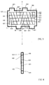
- Fig. 1 is schematic view showing a first preferred embodiment, wherein, a multi-directional, multiplexing radius convergence electrode having in both directions respectively provided with an I/O convergence terminal.
- Fig. 2 is a side view of the first preferred embodiment.
- an electrode 101 is provided with a conduction frame 100.
- an I/O terminal 201 is disposed along one side of a longitudinal central line V of the electrode 101.
- Another I/O terminal 401 is provided on side c opposite to side a diagonal to the I/O terminal 201 on the other side along the central line V .
- multiple conduction structures 501 are distributed in a mesh pattern on the electrode 101 and diffusing in radius towards their opposite sides.
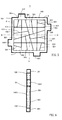
- Fig. 3 is a schematic view showing a multi-directional, multiplexing radius convergence electrode of a second preferred embodiment of the present invention having in both directions respectively provided with two I/O convergence terminals.
- Fig. 4 is a side view of the second preferred embodiment of the present invention.
- two sides of the electrode 101 are provided with the conduction frame 100.
- two I/O terminals 201, 202 are respectively disposed on both sides along the longitudinal central line V of the electrode 101.
- Two I/O terminals 401, 402 are provided on side c opposite to side ⁇ respectively diagonal to both I/O terminals 201, 202 on both sides along the central line V.
- both I/O terminals 201, 202, and both terminals 401, 402 are distributed in a mesh pattern on the electrode 101 and diffusing in radius towards their opposite sides.
- Fig. 5 is a schematic view showing a multi-directional, multiplexing radius convergence electrode of a third preferred embodiment of the present invention having in four directions respectively provided with an I/O convergence terminal.
- Fig. 6 is a side view of the third preferred embodiment of the present invention.
- an electrode 101 is provided with a conduction frame 100.
- an I/O terminal 201 is disposed along one side of a longitudinal central line V of the electrode 101.
- Another I/O terminal 401 is provided on side c opposite to side a diagonal to the I/O terminal 201 on the other side along the central line V.
- multiple conduction structures 501 are distributed in a mesh pattern on the electrode 101 and diffusing in radius towards their opposite sides.
- an I/O terminal 1201 is disposed along one side of a horizontal central line H of the electrode 101.
- Another I/O terminal 1401 is provided on side d opposite to side b diagonal to the I/O terminal 1201 on the other side along the central line H .
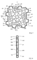
- Fig. 7 is a schematic view showing a multi-directional, multiplexing radius convergence electrode of a fourth preferred embodiment of the present invention having in both directions respectively provided with two I/O convergence terminals.
- Fig. 8 is a side view of the fourth preferred embodiment of the present invention.
- Figs. 7 and 8 four sides of the electrode 101 are provided with the conduction frame 100.
- two I/O terminals 201, 202 are respectively disposed on both sides along the longitudinal central line V of the electrode 101.
- Two I/O terminals 401, 402 are provided on side c opposite to side a respectively diagonal to both I/O terminals 201, 202 on both sides along the central line V.
- both I/O terminals 201, 202, and both terminals 401, 402 are distributed in a mesh pattern on the electrode 101 and diffusing in radius towards their opposite sides.
- two I/O terminals 1201, 1202 are respectively disposed on both sides along the horizontal central line H of the electrode 101.
- Two I/O terminals 1401, 1402 are provided on side d opposite to side b respectively diagonal to both I/O terminals 1201, 1202 on both sides along the central line H.
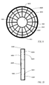
- Fig. 9 is a schematic view showing a fifth preferred embodiment of the present invention applied in a multi-directional, multiplexing radius convergence construction having at its center provided with a through hole and having its outer circumference as an I/O terminal electrode.
- Fig. 10 is a side view of the fifth preferred embodiment of the present invention.
- Fig. 11 is a schematic view showing a sixth preferred embodiment of the present invention applied in an electrode having a through hole at the center as an I/O terminal and provided with an electrode of multi-directional, multiplexing radius convergence construction.
- Fig. 12 is a side view of the sixth preferred embodiment.
- a circular electrode 1000 is provided at its center a through hole 2000, and the outer diameter respectively of a positive electrode and a negative electrode is not the same as the diameter of the through hole 2000.
- the electrode is provided in a greater outer diameter and the inner diameter of the through hole is also greater.
- a conduction frame 3000 is provided on the outer circumference of the electrode 1000 to form the I/O terminal; and multiple conduction structures 1501 are distributed in radius on the electrode with the conduction frame 3000 serving as a convergence I/O terminal.
- a circular conduction structure 5001 is provided. As illustrated in Fig.
- the sixth preferred embodiment of the present invention has an electrode in smaller outer diameter and the inner diameter of a through hole 2000 disposed at the center of the electrode 1000 is also smaller.
- a conduction frame 4000 provided on the circumference of the through hole 2000 constitutes an I/O terminal and multiple conduction structures 1601 are disposed in radius on the electrode having the conduction frame 4000 surrounding the central through hole 2000 as the convergence I/O terminal.
- multiple optional circular conduction structures 6001 may be provided.
- a loop conduction structure 7000 in oval, polygonal, or any other geometric shape as illustrated in Fig. 7 may be provided to replace the crossing point to avoid forming acute angles for facilitating the attachment of active substance coated and for achieving better conductivity.
- the present invention by providing an electrode in a construction of multi-directional, multiplexing convergence in radius specifically for the use by an electricity accumulation device, wherein, the individual convergence terminal being disposed on the side in all directions on the electrode to distribute a plurality of multi-directional, multiplexing conduction structures in radius towards the center of the electrode achieves consistent I/O amperage from the electrode as a whole and reduces internal impedance is innovative with specific functions and has never been disclosed before in the prior arts. Therefore, this application is duly filed accordingly.
Landscapes
- Chemical & Material Sciences (AREA)
- Chemical Kinetics & Catalysis (AREA)
- Electrochemistry (AREA)
- General Chemical & Material Sciences (AREA)
- Connection Of Batteries Or Terminals (AREA)
- Cell Electrode Carriers And Collectors (AREA)
- Hybrid Cells (AREA)
Priority Applications (4)
| Application Number | Priority Date | Filing Date | Title |
|---|---|---|---|
| CNA2005100645021A CN1848495A (zh) | 2005-04-11 | 2005-04-11 | 多向多路辐射状汇流结构的电极板 |
| CNA2006100885509A CN101083323A (zh) | 2005-04-11 | 2006-06-02 | 多向多路辐射状汇流结构的电极板 |
| JP2006188040A JP2008016374A (ja) | 2005-04-11 | 2006-07-07 | 多方向多重チャネルの放射状バス構造を呈する電極板 |
| EP06254561A EP1901377A1 (de) | 2005-04-11 | 2006-08-31 | Eine Elektrode |
Applications Claiming Priority (4)
| Application Number | Priority Date | Filing Date | Title |
|---|---|---|---|
| CNA2005100645021A CN1848495A (zh) | 2005-04-11 | 2005-04-11 | 多向多路辐射状汇流结构的电极板 |
| CNA2006100885509A CN101083323A (zh) | 2005-04-11 | 2006-06-02 | 多向多路辐射状汇流结构的电极板 |
| JP2006188040A JP2008016374A (ja) | 2005-04-11 | 2006-07-07 | 多方向多重チャネルの放射状バス構造を呈する電極板 |
| EP06254561A EP1901377A1 (de) | 2005-04-11 | 2006-08-31 | Eine Elektrode |
Publications (1)
| Publication Number | Publication Date |
|---|---|
| EP1901377A1 true EP1901377A1 (de) | 2008-03-19 |
Family
ID=50614620
Family Applications (1)
| Application Number | Title | Priority Date | Filing Date |
|---|---|---|---|
| EP06254561A Withdrawn EP1901377A1 (de) | 2005-04-11 | 2006-08-31 | Eine Elektrode |
Country Status (3)
| Country | Link |
|---|---|
| EP (1) | EP1901377A1 (de) |
| JP (1) | JP2008016374A (de) |
| CN (2) | CN1848495A (de) |
Cited By (1)
| Publication number | Priority date | Publication date | Assignee | Title |
|---|---|---|---|---|
| CN103840173A (zh) * | 2012-11-22 | 2014-06-04 | 神华集团有限责任公司 | 用于蓄电池的双极耳板栅 |
Families Citing this family (1)
| Publication number | Priority date | Publication date | Assignee | Title |
|---|---|---|---|---|
| CN102903423B (zh) * | 2012-10-25 | 2015-05-13 | 南昌欧菲光科技有限公司 | 透明导电膜中的导电结构、透明导电膜及制作方法 |
Citations (9)
| Publication number | Priority date | Publication date | Assignee | Title |
|---|---|---|---|---|
| US1069809A (en) * | 1913-02-04 | 1913-08-12 | Joseph C Kent | Storage battery. |
| US3556853A (en) * | 1969-06-05 | 1971-01-19 | Bell Telephone Labor Inc | Grid for lead-acid cell |
| US3989539A (en) * | 1975-12-01 | 1976-11-02 | Varta Batteries Ltd. | Battery grid |
| US4250235A (en) * | 1979-08-16 | 1981-02-10 | Hughes Aircraft Company | Battery electrode structure |
| US4320183A (en) * | 1981-02-09 | 1982-03-16 | Exide Corporation | Grid for batteries |
| JPS57123663A (en) * | 1981-01-23 | 1982-08-02 | Yuasa Battery Co Ltd | Paste type lead-acid battery |
| JPH02276161A (ja) * | 1989-04-17 | 1990-11-13 | Natl Space Dev Agency Japan<Nasda> | アルカリ―水素二次電池 |
| US5149605A (en) * | 1991-09-17 | 1992-09-22 | Globe-Union Inc. | Dual lug battery plate construction |
| US6159633A (en) * | 1998-01-14 | 2000-12-12 | Yang; Tai-Her | Electricity storage/discharge device with low internal resistance current collector structure |
Family Cites Families (6)
| Publication number | Priority date | Publication date | Assignee | Title |
|---|---|---|---|---|
| JPS51162933U (de) * | 1975-06-19 | 1976-12-25 | ||
| JPS5248632U (de) * | 1975-10-03 | 1977-04-06 | ||
| JPS53152134U (de) * | 1977-05-07 | 1978-11-30 | ||
| JPS55104261U (de) * | 1979-01-17 | 1980-07-21 | ||
| JPS6393068U (de) * | 1986-12-08 | 1988-06-16 | ||
| JP3000509B2 (ja) * | 1994-04-13 | 2000-01-17 | 古河電池株式会社 | 蓄電池用格子基板 |
-
2005
- 2005-04-11 CN CNA2005100645021A patent/CN1848495A/zh active Pending
-
2006
- 2006-06-02 CN CNA2006100885509A patent/CN101083323A/zh active Pending
- 2006-07-07 JP JP2006188040A patent/JP2008016374A/ja active Pending
- 2006-08-31 EP EP06254561A patent/EP1901377A1/de not_active Withdrawn
Patent Citations (9)
| Publication number | Priority date | Publication date | Assignee | Title |
|---|---|---|---|---|
| US1069809A (en) * | 1913-02-04 | 1913-08-12 | Joseph C Kent | Storage battery. |
| US3556853A (en) * | 1969-06-05 | 1971-01-19 | Bell Telephone Labor Inc | Grid for lead-acid cell |
| US3989539A (en) * | 1975-12-01 | 1976-11-02 | Varta Batteries Ltd. | Battery grid |
| US4250235A (en) * | 1979-08-16 | 1981-02-10 | Hughes Aircraft Company | Battery electrode structure |
| JPS57123663A (en) * | 1981-01-23 | 1982-08-02 | Yuasa Battery Co Ltd | Paste type lead-acid battery |
| US4320183A (en) * | 1981-02-09 | 1982-03-16 | Exide Corporation | Grid for batteries |
| JPH02276161A (ja) * | 1989-04-17 | 1990-11-13 | Natl Space Dev Agency Japan<Nasda> | アルカリ―水素二次電池 |
| US5149605A (en) * | 1991-09-17 | 1992-09-22 | Globe-Union Inc. | Dual lug battery plate construction |
| US6159633A (en) * | 1998-01-14 | 2000-12-12 | Yang; Tai-Her | Electricity storage/discharge device with low internal resistance current collector structure |
Cited By (1)
| Publication number | Priority date | Publication date | Assignee | Title |
|---|---|---|---|---|
| CN103840173A (zh) * | 2012-11-22 | 2014-06-04 | 神华集团有限责任公司 | 用于蓄电池的双极耳板栅 |
Also Published As
| Publication number | Publication date |
|---|---|
| CN1848495A (zh) | 2006-10-18 |
| JP2008016374A (ja) | 2008-01-24 |
| CN101083323A (zh) | 2007-12-05 |
Similar Documents
| Publication | Publication Date | Title |
|---|---|---|
| JP3165935U (ja) | 蓄電及び給電装置 | |
| EP4485599A3 (de) | Elektrode und sekundärbatterie damit | |
| JP3060540U (ja) | 蓄放電装置の低内部抵抗接続構造 | |
| EP4672407A3 (de) | Elektrode, sekundärbatterie mit der elektrode und verfahren zur herstellung der elektrode | |
| EP1998400A3 (de) | Akku für Fahrzeug und Fahrzeug | |
| US20060226757A1 (en) | Multi-directional multiplexing radius convergence electrode | |
| JP2015033566A5 (de) | ||
| US20190198844A1 (en) | Conductive sheet for connecting batteries and battery connecting module utilizing the same | |
| KR101300110B1 (ko) | 케이블형 이차전지 | |
| EP3854768A3 (de) | Aktive materialstruktur, elektrodenstruktur damit, sekundärbatterie damit und verfahren zu ihrer herstellung | |
| CN103560253A (zh) | 一种斜筋渐变结构的板栅 | |
| WO2006107702A3 (en) | Neural electrode array | |
| Hartvigsen | The potential of multi-purpose land consolidation in Eastern Europe | |
| CN205429182U (zh) | 一种环形多片接触导电弹片 | |
| CN218241891U (zh) | 一种复合集流体、电极极片及电化学装置 | |
| CN208310386U (zh) | 新型单杆横担结构 | |
| EP1258933A3 (de) | Elektrodenplatte für alkalische Speicherbatterie und alkalische Speicherbatterie, die diese verwendet | |
| JP2008016374A (ja) | 多方向多重チャネルの放射状バス構造を呈する電極板 | |
| US11536304B2 (en) | Clamp assembly | |
| CN207572936U (zh) | 防雷装置固定底座 | |
| EP1780743A3 (de) | Elektronenemissionsvorrichtung und diese verwendende Anzeigevorrichtung | |
| CN205609648U (zh) | 动力电池矩阵模组连接装置 | |
| CN207587778U (zh) | 一种带有镶嵌钢材紧固件的电池盖 | |
| CN107069223A (zh) | 可调谐天线及终端 | |
| CN219917496U (zh) | 电池和用电设备 |
Legal Events
| Date | Code | Title | Description |
|---|---|---|---|
| PUAI | Public reference made under article 153(3) epc to a published international application that has entered the european phase |
Free format text: ORIGINAL CODE: 0009012 |
|
| AK | Designated contracting states |
Kind code of ref document: A1 Designated state(s): AT BE BG CH CY CZ DE DK EE ES FI FR GB GR HU IE IS IT LI LT LU LV MC NL PL PT RO SE SI SK TR |
|
| AX | Request for extension of the european patent |
Extension state: AL BA HR MK YU |
|
| AKX | Designation fees paid | ||
| REG | Reference to a national code |
Ref country code: DE Ref legal event code: 8566 |
|
| 18D | Application deemed to be withdrawn |
Effective date: 20080820 |
|
| STAA | Information on the status of an ep patent application or granted ep patent |
Free format text: STATUS: THE APPLICATION IS DEEMED TO BE WITHDRAWN |
|
| R18D | Application deemed to be withdrawn (corrected) |
Effective date: 20080920 |