EP1901400B1 - Drahtabdeckung und Verschlusskonstruktion dafür - Google Patents
Drahtabdeckung und Verschlusskonstruktion dafür Download PDFInfo
- Publication number
- EP1901400B1 EP1901400B1 EP07017910A EP07017910A EP1901400B1 EP 1901400 B1 EP1901400 B1 EP 1901400B1 EP 07017910 A EP07017910 A EP 07017910A EP 07017910 A EP07017910 A EP 07017910A EP 1901400 B1 EP1901400 B1 EP 1901400B1
- Authority
- EP
- European Patent Office
- Prior art keywords
- engaging
- resilient
- portions
- wire
- connector
- Prior art date
- Legal status (The legal status is an assumption and is not a legal conclusion. Google has not performed a legal analysis and makes no representation as to the accuracy of the status listed.)
- Ceased
Links
- 238000010276 construction Methods 0.000 title description 3
- 230000013011 mating Effects 0.000 claims description 55
- 238000005452 bending Methods 0.000 claims description 3
- 238000006073 displacement reaction Methods 0.000 description 5
- 230000004308 accommodation Effects 0.000 description 2
- 230000000694 effects Effects 0.000 description 2
- 230000004048 modification Effects 0.000 description 2
- 238000012986 modification Methods 0.000 description 2
- 230000008719 thickening Effects 0.000 description 2
- 239000011230 binding agent Substances 0.000 description 1
- 230000001419 dependent effect Effects 0.000 description 1
- 230000002542 deteriorative effect Effects 0.000 description 1
- 238000007689 inspection Methods 0.000 description 1
- 238000000034 method Methods 0.000 description 1
- 230000000149 penetrating effect Effects 0.000 description 1
- 230000009467 reduction Effects 0.000 description 1
- 230000008439 repair process Effects 0.000 description 1
Images





Classifications
-
- H—ELECTRICITY
- H01—ELECTRIC ELEMENTS
- H01R—ELECTRICALLY-CONDUCTIVE CONNECTIONS; STRUCTURAL ASSOCIATIONS OF A PLURALITY OF MUTUALLY-INSULATED ELECTRICAL CONNECTING ELEMENTS; COUPLING DEVICES; CURRENT COLLECTORS
- H01R13/00—Details of coupling devices of the kinds covered by groups H01R12/70 or H01R24/00 - H01R33/00
- H01R13/46—Bases; Cases
- H01R13/502—Bases; Cases composed of different pieces
- H01R13/506—Bases; Cases composed of different pieces assembled by snap action of the parts
-
- H—ELECTRICITY
- H01—ELECTRIC ELEMENTS
- H01R—ELECTRICALLY-CONDUCTIVE CONNECTIONS; STRUCTURAL ASSOCIATIONS OF A PLURALITY OF MUTUALLY-INSULATED ELECTRICAL CONNECTING ELEMENTS; COUPLING DEVICES; CURRENT COLLECTORS
- H01R13/00—Details of coupling devices of the kinds covered by groups H01R12/70 or H01R24/00 - H01R33/00
- H01R13/58—Means for relieving strain on wire connection, e.g. cord grip, for avoiding loosening of connections between wires and terminals within a coupling device terminating a cable
- H01R13/5804—Means for relieving strain on wire connection, e.g. cord grip, for avoiding loosening of connections between wires and terminals within a coupling device terminating a cable comprising a separate cable clamping part
- H01R13/5812—Means for relieving strain on wire connection, e.g. cord grip, for avoiding loosening of connections between wires and terminals within a coupling device terminating a cable comprising a separate cable clamping part the cable clamping being achieved by mounting the separate part on the housing of the coupling device
Definitions
- the present invention relates to a wire cover, for example, to be mounted on wires connected with a connector, and to a locking construction therefor.
- a wire cover disclosed Japanese Unexamined Patent Publication No. 2004-348988 is known, for example, as a wire cover of this type.
- This wire cover is provided with a wire pressing portion to be brought into contact with bent parts of wires drawn out from a connector, and this wire pressing portion is fixed to a connector housing by a resilient engaging piece.
- a connector is arranged in a small space where other parts are densely arranged around.
- a connector housing cannot be provided with a locking structure for the wire cover since being maximally miniaturized.
- the wire cover is forced to be fixed to a mating member, to which the connector is attached, instead of being attached to the connector.
- a wire cover is fixed to a mating member in the door, to which this connector is attached, instead of being fixed to the connector as described above.
- a cover for a connector is known from US 2004/0102082 A1 .
- the cover has opposed halves with butting walls.
- An engaging projection is formed in an accommodation concavity rearward from an edge of the butting wall.
- a portion between the engaging projection and the edge on a bottom surface of the accommodation concavity defines a temporary holding surface which is contacted by a connection portion of a locking arm on the opposed half.
- the present invention was developed in view of the above problems, and an object thereof is to enable a wire pressing portion to be easily detached from a mating member by at least partly inserting a disengagement jig from the base end side of a resilient engaging piece of the wire pressing portion.
- a wire pressing portion to be easily detached from a mating member by at least partly inserting a disengagement jig from the base end side of a resilient engaging piece of the wire pressing portion.
- a wire cover for bending at least one wire or cable drawn out from a connector in a direction different from a draw-out direction comprising a connector-side fixing portion to be fixed to the connector, a wire pressing portion to be held substantially in contact with the wire, and a connecting portion connecting the connector-side fixing portion and wire pressing portion, wherein the wire pressing portion includes at least one resilient engaging piece projecting therefrom and formed with at least one engaging portion and can be fixed to a mating member at least partly fitted with or to the connector by engaging the at least one engaging portion with at least one engageable portion provided at the mating member, and at least one catching portion for disengagement, with which a jig at least partly inserted (particularly from the base end side of the resilient engaging piece) is brought into catching engagement to make the resilient engaging piece displaceable in such a direction as to disengage the engaging portion and engageable portion.
- the jig is to be at least partly inserted from the base end side of the resilient engaging piece to be brought into catching engagement with the at least one catching portion.
- the jig can be inserted from the base end side of the resilient engaging piece to bring the leading end thereof into catching engagement with the catching portion.
- the resilient engaging piece can be displaced in a disengaging direction to disengage the engaging portion and engageable portion. Therefore, the resilient engaging piece can be detached from the mating member by inserting the jig from the base end side of the resilient engaging piece.
- the mating member includes a pair of engaging wall portions each having the engageable portion and substantially facing each other, and a pair of resilient engaging pieces are so provided as to be fittable to the corresponding engaging wall portions from outer sides.
- each resilient engaging piece is integrally or unitarily formed with an auxiliary wall at least partly insertable at an inner side of the corresponding engaging wall portion to sandwich the engaging wall portion between the resilient engaging piece and the auxiliary wall.
- the engaging wall portions can be sandwiched between the resilient engaging pieces and auxiliary walls.
- the engaging portions and engageable portions can be held engaged. Even if the resilient engaging pieces should try to be resiliently deformed outward, there is no likelihood that the engaging portions and engageable portions are easily disengaged since the resilient engaging pieces become more difficult to resiliently deform than in the case where the resilient engaging pieces are provided-separately from the auxiliary walls.
- the engaging portions of the resilient engaging pieces are substantially in the form of engaging holes and the engageable portions of the engaging wall portions are in the form of engaging projections.
- engaging forces of the engaging projections and engaging holes are determined by the depth of the engaging holes, i.e. the thickness of the engaging wall portions.
- the depth of the engaging holes i.e. the thickness of the engaging wall portions.
- the resilient engaging pieces are thinned, this brings about a reduction in resilient forces, thereby losing the significance of integrally providing the resilient engaging pieces with the auxiliary walls.
- the depth of the engaging holes can be increased by thickening the resilient engaging pieces at sides opposite to the engaging wall portions. Therefore, the engaging forces can be enhanced without reducing the resilient forces of the resilient engaging pieces.
- a locking construction for a wire cover in particular according to the above invention or a preferred embodiment tehreof, including a wire pressing portion to be brought into contact with at least one bent part of at least one wire or cable drawn out from a connector, comprising:
- the disengagement jig preferably can be inserted from the base end side of the resilient engaging piece to insert the leading end thereof into a clearance between the engaging portion and mating member through the disengagement recess.
- the engaging portion can be disengaged by being displaced in a direction away from the mating member. Therefore, the resilient engaging piece can be detached from the mating member by inserting the disengagement jig from the base end side of the resilient engaging piece.
- a pair of resilient engaging pieces project to hold the engaging projection at least partly therebetween.
- each engaging portion is substantially bent or U-shaped as a whole by integrally or unitarily connecting at least the leading ends of the both resilient engaging pieces.
- the disengagement recesses can be located at positions seeable from the base end sides of the resilient engaging pieces with the resilient engaging pieces attached to the mating member. Further, the disengagement jig can be inserted in such a posture substantially parallel to a projecting direction of the resilient engaging pieces. Therefore, a disengaging operation can be more easily performed than in the case where through holes are formed at the leading end sides of the resilient engaging pieces and leading end parts of surrounding walls forming the through holes serve as engaging portions.
- the mating member includes a pair of engaging wall portions each having the engaging projection and substantially facing each other, and a pair of resilient engaging pieces are so provided as to be at least partly fittable to the corresponding engaging wall portions from outer sides.
- each resilient engaging piece is integrally or unitarily formed with at least one auxiliary wall at least partly insertable at an inner side of the corresponding engaging wall portion to sandwich or arrange the engaging wall portion between the resilient engaging piece and the auxiliary wall.
- the engaging wall portions can be sandwiched between the resilient engaging pieces and auxiliary walls.
- the engaging portions and engaging projections can be held engaged. Even if the resilient engaging pieces should try to be resiliently deformed outward, there is no likelihood that the engaging portions and engaging projections are easily disengaged since the resilient engaging pieces become more difficult to resiliently deform than in the case where the resilient engaging pieces are provided separately from the auxiliary walls.
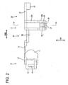
- a wire cover 1 of a preferred embodiment of the present invention is for bending one or more wires W (actually, a wire group formed by bundling a plurality of wires W, but merely called wires W in the following description) drawn out through a wire draw-out surface of a connector (not shown) attached to a mating member 40 in a direction different from a draw-out direction and guiding the wires W in a specified (predetermined or predeterminable) direction.
- FIG. 1 is a bottom view of the wire cover 1, and the unillustrated wires W are arranged at the bottom side of the wire cover 1.
- the wire cover 1 is provided with a connector-side fixing portion 10 to be fixed to the connector, a wire pressing portion 20 to be fixed to the mating member 40 and a connecting portion 30 integrally or unitarily connecting the connector-side fixing portion 10 and wire pressing portion 20.
- the mating member 40 is provided with one or more, preferably a pair of engaging wall portions 41 preferably substantially opposed to each other, and one or more, preferably a pair of engaging projections (corresponding to preferred engageable portions) 42 projecting from one or more surfaces of end portions of the (preferably both) engaging wall portion(s) 41 preferably substantially opposite to the facing surfaces as shown in FIG. 6 .
- FIG. 6 In the following description, reference is made to a direction normal to the plane of FIG.
- FIG. 1 concerning vertical direction VD with a back side set as an upper side, reference is made to transverse direction in FIG. 1 concerning forward and backward directions FBD with a shown right side set as a front side, and reference is made to vertical direction in FIG. 1 concerning width direction WD.
- the connector-side fixing portion 10 includes one or more, preferably a pair of side plates 11 preferably substantially facing each other in width direction WD, and the upper ends of the side plates 11 are connected by an upper end wall 12.
- One or more fixing plates 13 projecting substantially backward or along the forward and backward directions FBD are integrally or unitarily formed on the outer side surfaces of the (respective) side plate(s) 11, and one or more fixing grooves 14 extending substantially upward from the bottom end are formed in the fixing plate(s) 13.
- the fixing grooves 14 can fix the connector-side fixing portion 10 to the connector by being engaged with one or more lock projections (not shown) provided on the connector.
- the connecting portion 30 includes a flexible resilient portion 31 extending substantially forward from (preferably the front end edge of) the upper end wall 12, and a wire constraining portion 32 coupled to (preferably the front end edge of) the resilient portion 31.
- the width of the resilient portion 31 preferably is set slightly shorter than a distance between the both side plates 11 of the connector-side fixing portion 10.
- the resilient portion 31 comes to be arranged between the both side plates 11 and a bend accommodating portion is formed by the inner side surfaces of the both side plates 11 and the inner surface of the resilient portion 31.
- the wire constraining portion 32 preferably substantially is rod- or column-shaped and formed substantially not to be resiliently deformable or to have a significantly reduced resiliency as compared to the resilient portion 31.
- This wire constraining portion 32 is to be tied with or fixed to the wires W by a binding band, clamp or the like (not shown).
- the wire pressing portion 20 includes a (preferably substantially rectangular) base plate portion 21 having a rear portion (preferably the rear end edge) coupled to the wire constraining portion 32, and (preferably four) side walls projecting downward at the front and/or rear sides of the substantially opposite side edges of the base plate portion 21.
- the (preferably two) side wall(s) at the front side serve as one or more, preferably a pair of guiding projections 22 and the one or those at the rear side serve(s) as one or more, preferably a pair of resilient engaging pieces 23.
- the (preferably both) guiding projection(s) 22 project(s) downward from the (preferably substantially opposite) sides of (preferably the front end of) the base plate portion 21 preferably while substantially facing each other.
- a projecting height of the guiding projections 22 preferably is set substantially equal to or slightly larger than the diameter of the wires W. Since the lower surface of the base plate portion 21 is to come substantially in contact with the wires W due to resilient forces of the wires W when the wires W are bent, the wires W can be reliably guided to extend substantially forward or along the forward and backward directions FBD from (preferably the front end of) the base plate portion 21 by arranging the wires W at least partly adjacent to or between the both guiding projections 22.
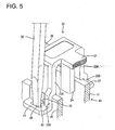
- the (preferably both) resilient engaging pieces 23 include one or more deformation restricted portions 23A extending downward from the (preferably substantially opposite) side(s) of (preferably the rear end of) the base plate portion 21 preferably while substantially facing each other, and one or more deformation permitted portions 23B projecting downward from the outer side surfaces of (preferably the bottom ends of) the deformation restricted portions 23A while being supported only one side.
- Each deformation permitted portion 23B is comprised of one or more, preferably a pair of supporting arms 23B1 projecting in such a manner as to hold the engaging projection 42 close thereto or at least partly therebetween, and preferably a bridging portion 23B2 bridging the leading ends of the both supporting arms 23B1 to integrally or unitarily connect them, and is substantially U-shaped as a whole.
- the upper surface of the bridging portion 23B2 is set at a position lower than the bottom surfaces of the deformation restricted portions 23A, whereby an engaging hole (corresponding to a preferred engaging portion) 25 is formed by the substantially opposite inner surfaces of the both supporting arms 23B1, the upper surface of the bridging portion 23B2 and the lower surface of the deformation restricted portion 23A.
- the engaging hole 25 enables the wire pressing portion 20 to be fixed to the mating member 40 by being engaged with the engaging projection 42.
- the lower surface of the base plate portion 21 receives upward acting resilient repulsive forces from the bent wires W and the lower surfaces of the engaging projections 42 and the upper surfaces of the bridging portions 23B2 are held substantially in contact with each other.
- clearances S are formed between the lower surfaces of the deformation restricted portions 23A and the upper surfaces of the engaging wall portions 41.
- the clearances S ( FIG. 6 ) are provided because the upper surfaces of the bridging portions 23B2 make pivotal displacements about the base ends thereof and the bridging portions 23B2 pass positions above those before the displacements upon moving over the engaging projections 42. Accordingly, the clearances S are set to have such a length as to enable the bridging portions 23B2 to move over the engaging projections 42 with the lower surfaces of the deformation restricted portions 23A and the upper surfaces of the engaging wall portions 41 held in contact.
- auxiliary walls 24 projecting substantially downward from the base plate portion 21 preferably while substantially facing each other are formed on the inner side(s) of the (preferably both) resilient engaging piece(s) 23.
- Each auxiliary wall 24 is comprised of a facing wall 24 arranged to substantially face the resilient engaging piece 23 and restricting walls 24B for restricting a resilient deformation of the facing wall 24A by extending outward substantially in width direction WD from the front and rear edges of the facing wall 24A, and is in the form of a column having a U-shaped cross section as a whole.
- the bottom ends of the auxiliary walls 24 are set at such height positions preferably substantially aligned with the bottom ends of the deformation permitted portions 23B.
- the outer widthwise edges of the restricting walls 24B are integrally or unitarily connected with the deformation restricted portions 23A, whereby the restricting walls 24B can restrict resilient deformations of the deformation restricted portions 23A while permitting only resilient deformations of the deformation permitted portions 23B substantially in width direction WD. Further, resilient forces of the deformation permitted portions 23B become larger than in the case where the deformation restricted portions 23A and the auxiliary walls 24 are separately formed, wherefore the engaging holes 25 and engaging projections 42 can be engaged with enhanced forces. It should be noted that a distance between the inner surfaces of the deformation permitted portions 23B and the lateral ends of the restricting walls 24B preferably is set substantially equal to or slightly larger than the thickness of the engaging wall portions 41.
- a bulging portion 27 projecting outward substantially in width direction WD is formed on the outer side surface of the bridging portion 23B2 of each deformation permitted portion 23B.
- This bulging portion 27 is formed with a catching hole (corresponding to a preferred catching portion) 26 penetrating substantially in vertical direction (projecting direction of the deformation permitted portion 23B).
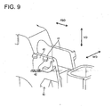
- the catching hole 26 is located at a position which can be seen from the base end side of the resilient engaging piece 23 and dimensioned such that a minus driver 50 (corresponding to a preferred jig) is at least partly insertable thereinto from the base end side of the resilient engaging piece 23.
- the deformation permitted portion 23B can be displaced outward substantially in width direction WD (direction to disengage the engaging hole 25 and engaging projection 42) by at least partly inserting the substantially flat or minus driver 50 from the base end side of the resilient engaging piece 23 and bringing it into catching engagement with the catching hole 26.
- the catching hole 26 is located at the position which can be seen from the base end side of the resilient engaging piece 23 because it is difficult to at least partly insert the leading end of the minus driver 50 into the catching hole 26 even if the minus driver 50 is at least partly inserted from the base end side of the resilient engaging piece 23 in the case where the catching hole 26 should be located at a position unseeable from the base end side of the resilient engaging piece 23.
- the attachment of the wire pressing portion 20 to the mating member 40 is described.
- the resilient portion 31 is resiliently deformed and the wires W are at least partly bent, whereby the wires W come substantially into contact with the lower surface of the base plate portion 21 by resilient repulsive forces of the wires W.
- the engaging wall portions 41 at least partly enter between the deformation permitted portions 23B and the auxiliary walls 24, and the leading ends of the deformation permitted portions 23B move onto the engaging projections 42 to resiliently deform the deformation permitted portions 23B outward in width direction WD.
- the deformation permitted portions 23B When the leading ends of the deformation permitted portions 23B move over the engaging projections 42, the deformation permitted portions 23B are resiliently at least partly restored to engage the engaging holes 25 and engaging projections 42. In this way, the wire pressing portion 20 is fixed to the mating member 40.
- the leading end of the minus driver 50 is at least partly inserted into one catching hole 25 from the base end side of the resilient engaging piece 23. Then, the leading end of the minus driver 50 is displaced in such a disengaging direction (preferably outward substantially in width direction WD) to disengage the engaging hole 25 and engaging projection 42. Subsequently, the leading end of the minus driver 50 is or can be at least partly inserted into the other catching hole 25 from the base end side of the resilient engaging piece 23 and displaced in the disengaging direction (outward in width direction WD) to disengage the engaging hole 25 and engaging projection 42, whereby the wire pressing portion 20 can be detached from the mating member 40.
- a disengaging direction preferably outward substantially in width direction WD
- this embodiment has the following effects.
- a wire cover 1 is provided with a connector-side fixing portion 10 to be fixed to a connector, a wire pressing portion 20 to be held substantially in contact with one or more wires or cables W, and a connecting portion 30 connecting the connector-side fixing portion 10 and wire pressing portion 20.
- One or more resilient engaging pieces 23 formed with one or more respective engaging holes 25 project from the wire pressing portion 20, and the wire pressing portion 20 can be fixed to a mating member 40 at least partly fitted with the connector by engaging the one or more engaging holes 25 with one or more respective engaging projections 42 provided at the mating member 40.
- At or near the leading ends of the resilient engaging pieces 23 are formed one or more catching holes 26 used for disengagement, with each of which a jig 50 at least partly inserted from the base end side of the resilient engaging piece 23 can be brought into catching engagement to displace the resilient engaging piece 23 in such a direction as to disengage the engaging hole 25 and engaging projection 42.
- a wire cover 1 is provided with a wire pressing portion 20 to be held in contact with one or more bent parts of one or more wires or cables W (actually, a wire group formed by bundling a plurality of wires W, but merely called wires W in the following description) drawn out from a connector (not shown), and the wire pressing portion 20 is to be fixed to a mating member 40 to which the connector is attached. As shown in FIG.
- the mating member 40 is provided with one or more, preferably a pair of engaging wall portions 41 facing each other, and one or more, preferably a pair of engaging projections 42 projecting from one or more surfaces of end portions of the both engaging wall portions 41 preferably substantially opposite to the facing surfaces of the (preferably both) engaging wall portions 41.
- Each engaging projection 42 is comprised of one or more, preferably a pair of projections spaced apart by a specified (predetermined or predeterminable) distance.
- the wire pressing portion 20 includes a bend accommodating portion 20A for at least partly accommodating the bent parts of the wires W, a wire constraining portion 20B to be tied with or fixed to the wires W by a binding band, binder, clip or the like (not shown), and a lock portion 20C coupled to the bend accommodating portion 20A via the wire constraining portion 20B and to be fixed to the mating member 40.
- the lock portion 20C is comprised of a (preferably substantially rectangular) base plate portion 21 connected with the wire constraining portion 20B and a pair of side plates 22 projecting substantially downward from the opposite side edges of the base plate portion 21, and preferably substantially has a U-shaped cross section as a whole.
- On the outer side surfaces of the both side plates 22, one or more, preferably a pair of resilient engaging pieces 23 are formed to project substantially downward from (preferably the bottom ends of) the (preferably both) side plates 22 preferably while substantially facing each other and being supported only at one side.
- Each resilient engaging piece 23 is comprised of one or more, preferably a pair of supporting arms 23A projecting to hold the engaging projection close thereto or at least partly therebetween and an engaging portion 23B projecting from, preferably bridging the leading ends of the both supporting arms 23A preferably to integrally or unitarily couple them, and has a bent or substantially U-shaped cross section as a whole.
- the engaging portion 23B is located at a position which can be seen from the base end side of the resilient engaging piece 23, and a disengagement jig (such as a minus or flat driver 50 to be described later) can be at least partly inserted preferably in such a posture substantially parallel to a projecting direction of the resilient engaging piece 23.
- the distal or upper surface of the engaging portion 23B is set at a position lower than the bottom surfaces of the side plates 22, whereby an engaging hole 25 is formed by the opposite inner surfaces of the both supporting arms 23A, the upper surface of the engaging portion 23B and the lower surface of the side plate 22.
- the engaging hole 25 is engageable with the engaging projection 42 and can fix the wire pressing portion 20 to the mating member 40 by the engagement of the upper surface of the engaging portion 23B and the lower surface of the engaging projection 42.
- the engaging portion 23B preferably is formed thinner than the supporting arms 23B by having the inner side thereof thinned. Accordingly, the inner surface of the engaging portion 23B is at a specified (predetermined or predeterminable) distance from the outer surface of the engaging wall portion 41.
- the lower surface of the base plate portion 21 receives upward acting resilient repulsive forces from the bent wires W and the lower surfaces of the engaging projections 42 and the upper surfaces of the engaging portions 23B are urged towards each other and/or held substantially in contact with each other.
- clearances S are formed between the lower surfaces of the side plates 22 and the upper surfaces of the engaging wall portions 41.
- the clearances S are provided because the upper surfaces of the engaging portions 23B make pivotal displacements about the base ends thereof and the engaging portions 23B pass positions above those before the displacements upon moving over the engaging projections 42. Accordingly, the clearances S are set to have such a length as to enable the engaging portions 23B to move over the engaging projections 42 with the lower surfaces of the side plates 22 and the upper surfaces of the engaging wall portions 41 held in contact.
- Each auxiliary wall 24 preferably is comprised of a facing wall 24A arranged to face the side plate 22 and one or more restricting walls 24B for restricting a resilient deformation of the facing wall 24A by extending substantially outward in width direction WD from the front and/or rear portions or edges of the facing wall 24A, and preferably is in the form of a column having a U-shaped cross section as a whole.
- the bottom ends of the auxiliary walls 24 preferably are set at such height positions substantially aligned with the bottom ends of the resilient engaging pieces 23.
- the outer widthwise edges of the restricting walls 24B are integrally or unitarily connected with the side plate 22, whereby the restricting walls 24B can restrict resilient deformations of the side plates 22 while permitting only resilient deformations of the resilient engaging pieces 23 in width direction WD.
- engaging forces of the engaging holes 25 and engaging projections 42 can be more enhanced as compared to the case where the side plates 22 are formed separately from the auxiliary walls 24.
- a distance between the inner surfaces of the supporting arms 23A and the lateral ends of the restricting walls 24B preferably is set substantially equal to or slightly larger than the thickness of the engaging wall portions 41.
- each engaging projection 42 preferably is comprised of a front projection 42A and a rear projection 42B at a specified (predetermined or predeterminable) distance from each other.
- a disengagement recess 43 is defined between the both projections 42A, 42B, and the engaging portion 23B is located at the position which can be seen from the base end side of the resilient engaging piece 23 through this disengagement recess 43.
- the spacing between the both projections 42A, 42B is set such that the leading end of the minus driver 50 (corresponding to a preferred jig or disengagement jig) is at least partly insertable.
- the spacing between the inner surface of the engaging portion 23B and the outer surface of the engaging wall portion 41 is set such that the leading end of the minus driver 50 is at least partly insertable.
- the resilient engaging piece 23 can be resiliently displaced in such a direction (preferably substantially outward in width direction WD) to disengage the engaging hole 25 and engaging projection 42 by at least partly inserting the minus driver 50 from the base end side of the resilient engaging piece 23 and at least partly inserting the leading end of the minus driver 50 into the clearance between the inner surface of the engaging portion 23B and the outer surface of the engaging wall portion 41 through the disengagement recess 43.
- the minus driver 50 cannot be inserted into the disengagement recess 43.
- the disengagement recess 43 is located at the position which can be seen from the base end side of the resilient engaging piece 23.
- the attachment of the wire pressing portion 20 to the mating member 40 is described.
- the wire pressing portion 20 is pushed substantially toward the engaging projections 42, the wires W are bent, the bent parts of the wires W are at least partly accommodated into the bend accommodating portion 20A, and the wires W at least partly come substantially into contact with the lower surface of the base plate portion 21 by resilient repulsive forces of the wires W.
- the engaging wall portions 41 at least partly enter between the resilient engaging pieces 23 and auxiliary walls 24, and the engaging portions 23B move onto or over the engaging projections 42 to resiliently deform the resilient engaging pieces 23 in a deforming direction (preferably substantially outward in width direction WD).
- the resilient engaging pieces 23 are resiliently at least partly restored to engage the engaging portions 23B and engaging projections 42. In this way, the wire pressing portion 20 is fixed to the mating member 40.
- the leading end of the minus driver 50 is at least partly inserted through the disengagement recess 43 from the base end side of one resilient engaging piece 23 to at least partly enter the clearance between the engaging portion 23B and engaging wall portion 41. Then, the leading end of the minus driver 50 is displaced in a displacement direction (preferably substantially outward in width direction WD) to disengage the engaging portion 23B and engaging projection 42.
- the leading end of the minus driver 50 is or can be at least partly inserted through the disengagement recess 43 from the base end side of the other resilient engaging piece 23 to at least partly enter the clearance between the engaging portion 23B and engaging wall portion 41, thereby displacing the resilient engaging piece 23 (preferably substantially outward in width direction WD) to disengage the engaging portion 23B and engaging projection 42.
- the wire pressing portion 20 can be detached from the mating member 40.
- this example has the following effects.
- a wire cover 1 is provided with a wire pressing portion 20 to be brought into contact with one or more bent parts of one or more wires W drawn out from a connector.
- a mating member 40 to or with which the connector is attached or connected includes one or more, preferably a pair of engaging wall portions 41 having one or more engaging projections 42 and preferably substantially facing each other.
- One or more resilient engaging pieces 23 project from the wire pressing portion 20 substantially toward the engaging projection(s) 42.
- Each resilient engaging piece 23 includes an engaging portion 23B for fixing the resilient engaging piece 23 to the mating member 40 by being engaged with the corresponding engaging projection 42.
- Each engaging projection 42 is formed with at least one disengagement recess 43 for at least partly receiving the leading end of a minus driver 50 at least partly inserted from the base end side of the resilient engaging piece 23 so that the engaging portion 23B can be displaced by the minus driver 50 to be disengaged from the engaging projection 42.
Landscapes
- Installation Of Indoor Wiring (AREA)
- Connector Housings Or Holding Contact Members (AREA)
- Details Of Connecting Devices For Male And Female Coupling (AREA)
Claims (5)
- Drahtabdeckung (1) zum Biegen wenigstens eines Drahts (W), der aus einem Verbinder in eine von einer von der Herausziehrichtung verschiedenen Richtung herausgezogen wird, die umfasst:einen verbinderseitigen Befestigungsabschnitt (10), der an dem Verbinder befestigt werden soll,einen Drahtdruckabschnitt (20), der im Wesentlichen in Kontakt mit dem Draht (W) gehalten werden soll, undeinen Verbindungsabschnitt (30), der den verbinderseitigen Befestigungsabschnitt (10) und den Drahtdruckabschnitt (20) verbindet,dadurch gekennzeichnet, dassder Drahtdruckabschnitt (20) wenigstens ein von ihm vorstehendes elastisches Eingreifstück (23) umfasst und mit wenigstens einem Eingreifabschnitt (25) ausgebildet ist und an einem Gegenstück (40) befestigt werden kann, das zumindest teilweise mit oder an dem Verbinder eingepasst ist, indem der wenigstens eine Eingreifabschnitt (25) mit dem wenigstens einen eingreifbaren Abschnitt (42), der an dem Gegenstück (40) bereitgestellt ist, in Eingriff gebracht wird, undwenigstens ein Halteabschnitt (26) zum Lösen, mit dem eine Spannvorrichtung (50), die zumindest teilweise von der Basisendseite des elastischen Eingreifstücks (23) eingesetzt ist, in einen Halteeingriff gebracht wird, um das elastische Eingreifstück (23) in eine derartige Richtung verschiebbar zu machen, dass der Eingreifabschnitt (25) und der eingreifbare Abschnitt (42) gelöst werden.
- Drahtabdeckung nach Anspruch 1, wobei die Spannvorrichtung (50) zumindest teilweise von der Basisendseite des elastischen Eingreifstücks (23) eingesetzt werden soll, um in einen Halteeingriff mit dem wenigstens einen Halteabschnitt (26) gebracht zu werden.
- Drahtabdeckung nach einem oder mehreren der vorhergehenden Ansprüche, wobei:das Gegenstück (40) ein Paar von Eingreifwandabschnitten (41) umfasst, von denen jeder den eingreifbaren Abschnitt (42) umfasst, die sich im Wesentlichen gegenüberliegen, undein Paar elastischer Eingreifstücke (23) derart bereitgestellt ist, dass sie von Außenseiten an die entsprechenden Eingreifwandabschnitte (41) anpassbar bzw. montierbar sind.
- Drahtabdeckung nach Anspruch 3, wobei jedes elastische Eingreifstück (23) integral oder einheitlich mit einer Hilfswand (24) ausgebildet ist, die zumindest teilweise auf einer Innenseite des entsprechenden Wandeingreifabschnitts (41) einsetzbar ist, um den Eingreifwandabschnitt (41) zwischen dem elastischen Eingreifstück (23) und der Hilfswand (24) einzuschieben.
- Drahtabdeckung nach Anspruch 4, wobei die Eingreifabschnitte (25) der elastischen Eingreifstücke (24) im Wesentlichen die Form von Eingreiflöchern (25) haben und die eingreifbaren Abschnitte (42) der Eingreifwandabschnitte (41) die Form von Eingreifvorsprüngen (42) haben.
Applications Claiming Priority (2)
| Application Number | Priority Date | Filing Date | Title |
|---|---|---|---|
| JP2006248456A JP4891714B2 (ja) | 2006-09-13 | 2006-09-13 | 電線カバーのロック構造 |
| JP2006248457A JP2008071600A (ja) | 2006-09-13 | 2006-09-13 | 電線カバー |
Publications (3)
| Publication Number | Publication Date |
|---|---|
| EP1901400A2 EP1901400A2 (de) | 2008-03-19 |
| EP1901400A3 EP1901400A3 (de) | 2008-06-11 |
| EP1901400B1 true EP1901400B1 (de) | 2010-08-25 |
Family
ID=38670045
Family Applications (1)
| Application Number | Title | Priority Date | Filing Date |
|---|---|---|---|
| EP07017910A Ceased EP1901400B1 (de) | 2006-09-13 | 2007-09-12 | Drahtabdeckung und Verschlusskonstruktion dafür |
Country Status (3)
| Country | Link |
|---|---|
| US (1) | US7458841B2 (de) |
| EP (1) | EP1901400B1 (de) |
| DE (1) | DE602007008658D1 (de) |
Families Citing this family (4)
| Publication number | Priority date | Publication date | Assignee | Title |
|---|---|---|---|---|
| TWM428632U (en) * | 2011-11-18 | 2012-05-01 | Mu-Sheng Lin | Fixing device |
| JP2017059421A (ja) * | 2015-09-17 | 2017-03-23 | 住友電装株式会社 | 電線カバー |
| CN110694284B (zh) * | 2019-09-23 | 2021-12-31 | 深圳市优必选科技股份有限公司 | 积木玩具及其连接组件 |
| WO2026059651A1 (en) * | 2024-09-12 | 2026-03-19 | KYOCERA AVX Components Corporation | Low-profile connector |
Family Cites Families (9)
| Publication number | Priority date | Publication date | Assignee | Title |
|---|---|---|---|---|
| JP2515735Y2 (ja) * | 1990-11-21 | 1996-10-30 | 住友電装株式会社 | ワイヤーハーネスのコネクタカバー |
| US6364693B1 (en) * | 1999-05-21 | 2002-04-02 | International Truck And Engine Corp. | Backshell with forced electrical connector orientation |
| US7021959B2 (en) | 2002-11-22 | 2006-04-04 | Sumitomo Wiring Systems, Ltd. | Wire cover with two longitudinal halves connectable around electric wires |
| JP2004288545A (ja) * | 2003-03-24 | 2004-10-14 | Yazaki Corp | コネクタ用プロテクタ |
| JP2004348988A (ja) | 2003-05-20 | 2004-12-09 | Sumitomo Wiring Syst Ltd | 電線カバーの取付構造 |
| US7241183B2 (en) | 2005-01-31 | 2007-07-10 | Delphi Technologies, Inc. | Electrical connector with integrated terminal position assurance and wire cover |
| JP4656579B2 (ja) * | 2006-03-29 | 2011-03-23 | 住友電装株式会社 | コネクタ接続構造及びクランプ部材 |
| JP4830770B2 (ja) * | 2006-10-06 | 2011-12-07 | 住友電装株式会社 | 電線ホルダ |
| JP4760686B2 (ja) * | 2006-11-24 | 2011-08-31 | 住友電装株式会社 | ロック構造 |
-
2007
- 2007-09-12 US US11/900,565 patent/US7458841B2/en not_active Expired - Fee Related
- 2007-09-12 DE DE602007008658T patent/DE602007008658D1/de active Active
- 2007-09-12 EP EP07017910A patent/EP1901400B1/de not_active Ceased
Also Published As
| Publication number | Publication date |
|---|---|
| EP1901400A3 (de) | 2008-06-11 |
| US7458841B2 (en) | 2008-12-02 |
| DE602007008658D1 (de) | 2010-10-07 |
| EP1901400A2 (de) | 2008-03-19 |
| US20080064261A1 (en) | 2008-03-13 |
Similar Documents
| Publication | Publication Date | Title |
|---|---|---|
| US20060252300A1 (en) | Connector for flat cable | |
| JP5704021B2 (ja) | ゴム栓及び防水コネクタ | |
| EP1923962B1 (de) | Stecker und Vormontageverfahren dafür | |
| CN104662742A (zh) | 连接器 | |
| CN103633471A (zh) | 扁平导体用电连接器 | |
| EP1909363B1 (de) | Drahthalter und Drahthalteverfahren | |
| JP2004281207A (ja) | コネクタ | |
| JP2001023729A (ja) | コネクタ | |
| CN102005669B (zh) | 电线连接器 | |
| JP2006179266A (ja) | コネクタ | |
| EP1901400B1 (de) | Drahtabdeckung und Verschlusskonstruktion dafür | |
| EP1926193B1 (de) | Verriegelungskonstruktion, Steckverbinder damit und Entriegelungsverfahren | |
| JP2019067744A (ja) | コネクタ | |
| EP1801925B1 (de) | Verbinder und Verbinderanordnung | |
| CN103380549A (zh) | 连接器和用于连接器的组装夹具 | |
| CN110383595A (zh) | 连接器 | |
| KR20140016819A (ko) | 커넥터 | |
| JP2022023258A (ja) | コネクタ | |
| JP3741350B2 (ja) | 半嵌合防止コネクタ | |
| JP2008177096A (ja) | コネクタのロック機構 | |
| JP5217602B2 (ja) | コネクタ | |
| JP3256782B2 (ja) | ロック機構付コネクタ | |
| JP2008198392A (ja) | ジョイントコネクタ | |
| JP4428348B2 (ja) | コネクタ | |
| JP4891714B2 (ja) | 電線カバーのロック構造 |
Legal Events
| Date | Code | Title | Description |
|---|---|---|---|
| PUAI | Public reference made under article 153(3) epc to a published international application that has entered the european phase |
Free format text: ORIGINAL CODE: 0009012 |
|
| 17P | Request for examination filed |
Effective date: 20071011 |
|
| AK | Designated contracting states |
Kind code of ref document: A2 Designated state(s): AT BE BG CH CY CZ DE DK EE ES FI FR GB GR HU IE IS IT LI LT LU LV MC MT NL PL PT RO SE SI SK TR |
|
| AX | Request for extension of the european patent |
Extension state: AL BA HR MK YU |
|
| PUAL | Search report despatched |
Free format text: ORIGINAL CODE: 0009013 |
|
| AK | Designated contracting states |
Kind code of ref document: A3 Designated state(s): AT BE BG CH CY CZ DE DK EE ES FI FR GB GR HU IE IS IT LI LT LU LV MC MT NL PL PT RO SE SI SK TR |
|
| AX | Request for extension of the european patent |
Extension state: AL BA HR MK RS |
|
| RIN1 | Information on inventor provided before grant (corrected) |
Inventor name: FUNAYAMA, TOMOYUKITOYOTA JIDOSHA KABUSIKI KAISHA, Inventor name: KOBAYASHI,HIROSHITOYOTA JIDOSHA KABUSHIKI KAISHA, Inventor name: KAKEGAWA, TOMOOTOYOTA JIDOSHA KABUSHIKI KAISHA, Inventor name: NISHIYAMA, SHIGEKITOYOTA JIDOSHA KABUSHIKI KAISHA, Inventor name: KOBAYASHI, TOMOHIKO,SUMITOMO WIRING SYSTEMS LTD. 1 |
|
| RIN1 | Information on inventor provided before grant (corrected) |
Inventor name: KOBAYASHI,HIROSHI Inventor name: NISHIYAMA, SHIGEKI Inventor name: KOBAYASHI, TOMOHIKO Inventor name: FUNAYAMA, TOMOYUKI Inventor name: KAKEGAWA, TOMOO |
|
| 17Q | First examination report despatched |
Effective date: 20081106 |
|
| AKX | Designation fees paid |
Designated state(s): DE FR |
|
| GRAP | Despatch of communication of intention to grant a patent |
Free format text: ORIGINAL CODE: EPIDOSNIGR1 |
|
| GRAS | Grant fee paid |
Free format text: ORIGINAL CODE: EPIDOSNIGR3 |
|
| GRAA | (expected) grant |
Free format text: ORIGINAL CODE: 0009210 |
|
| AK | Designated contracting states |
Kind code of ref document: B1 Designated state(s): DE FR |
|
| REF | Corresponds to: |
Ref document number: 602007008658 Country of ref document: DE Date of ref document: 20101007 Kind code of ref document: P |
|
| PLBE | No opposition filed within time limit |
Free format text: ORIGINAL CODE: 0009261 |
|
| STAA | Information on the status of an ep patent application or granted ep patent |
Free format text: STATUS: NO OPPOSITION FILED WITHIN TIME LIMIT |
|
| 26N | No opposition filed |
Effective date: 20110526 |
|
| REG | Reference to a national code |
Ref country code: DE Ref legal event code: R097 Ref document number: 602007008658 Country of ref document: DE Effective date: 20110526 |
|
| REG | Reference to a national code |
Ref country code: FR Ref legal event code: PLFP Year of fee payment: 10 |
|
| REG | Reference to a national code |
Ref country code: DE Ref legal event code: R084 Ref document number: 602007008658 Country of ref document: DE |
|
| REG | Reference to a national code |
Ref country code: FR Ref legal event code: PLFP Year of fee payment: 11 |
|
| PGFP | Annual fee paid to national office [announced via postgrant information from national office to epo] |
Ref country code: DE Payment date: 20170905 Year of fee payment: 11 Ref country code: FR Payment date: 20170810 Year of fee payment: 11 |
|
| REG | Reference to a national code |
Ref country code: DE Ref legal event code: R119 Ref document number: 602007008658 Country of ref document: DE |
|
| PG25 | Lapsed in a contracting state [announced via postgrant information from national office to epo] |
Ref country code: DE Free format text: LAPSE BECAUSE OF NON-PAYMENT OF DUE FEES Effective date: 20190402 |
|
| PG25 | Lapsed in a contracting state [announced via postgrant information from national office to epo] |
Ref country code: FR Free format text: LAPSE BECAUSE OF NON-PAYMENT OF DUE FEES Effective date: 20180930 |