EP1901410A2 - Chargeur de plusieurs batteries - Google Patents
Chargeur de plusieurs batteries Download PDFInfo
- Publication number
- EP1901410A2 EP1901410A2 EP07017415A EP07017415A EP1901410A2 EP 1901410 A2 EP1901410 A2 EP 1901410A2 EP 07017415 A EP07017415 A EP 07017415A EP 07017415 A EP07017415 A EP 07017415A EP 1901410 A2 EP1901410 A2 EP 1901410A2
- Authority
- EP
- European Patent Office
- Prior art keywords
- battery
- charging
- recharging
- terminal
- circuitry
- Prior art date
- Legal status (The legal status is an assumption and is not a legal conclusion. Google has not performed a legal analysis and makes no representation as to the accuracy of the status listed.)
- Withdrawn
Links
Images



Classifications
-
- H—ELECTRICITY
- H02—GENERATION; CONVERSION OR DISTRIBUTION OF ELECTRIC POWER
- H02J—ELECTRIC POWER NETWORKS; CIRCUIT ARRANGEMENTS OR SYSTEMS FOR SUPPLYING OR DISTRIBUTING ELECTRIC POWER; SYSTEMS FOR STORING ELECTRIC ENERGY
- H02J7/00—Circuit arrangements for charging or discharging batteries or for supplying loads from batteries
- H02J7/60—Circuit arrangements for charging or discharging batteries or for supplying loads from batteries including safety or protection arrangements
- H02J7/685—Circuit arrangements for charging or discharging batteries or for supplying loads from batteries including safety or protection arrangements using connection detecting circuits
-
- H—ELECTRICITY
- H02—GENERATION; CONVERSION OR DISTRIBUTION OF ELECTRIC POWER
- H02J—ELECTRIC POWER NETWORKS; CIRCUIT ARRANGEMENTS OR SYSTEMS FOR SUPPLYING OR DISTRIBUTING ELECTRIC POWER; SYSTEMS FOR STORING ELECTRIC ENERGY
- H02J7/00—Circuit arrangements for charging or discharging batteries or for supplying loads from batteries
- H02J7/485—Circuit arrangements for charging or discharging batteries or for supplying loads from batteries with provisions for charging different types of batteries
-
- H—ELECTRICITY
- H02—GENERATION; CONVERSION OR DISTRIBUTION OF ELECTRIC POWER
- H02J—ELECTRIC POWER NETWORKS; CIRCUIT ARRANGEMENTS OR SYSTEMS FOR SUPPLYING OR DISTRIBUTING ELECTRIC POWER; SYSTEMS FOR STORING ELECTRIC ENERGY
- H02J7/00—Circuit arrangements for charging or discharging batteries or for supplying loads from batteries
- H02J7/70—Circuit arrangements for charging or discharging batteries or for supplying loads from batteries characterised by the mechanical construction
Definitions
- the present invention relates to a charger, and more particularly to a multi-battery charger which is capable of charging battery of different sizes, and irrespective of polarity of the battery terminals.
- a conventional charger such as a conventional battery charger for a cellular phone battery, usually comprises a charger case having a battery slot formed thereon, a positive charging pin and a negative charging pin spacedly provided within the battery slot for aligning with a battery terminal and a negative battery terminal of the battery respectively, and a charging circuitry provided within the charger case to electrically connect with the positive charging pin and the negative charging pin.
- the charging circuitry can be activated to start charging of the battery through the positive charging pin and the negative charging pin.
- a charger of a particular rechargeable battery designed for use in a particular model or particular brand of cellular phones may only be utilized for charging that particular type of rechargeable battery. This may be accomplished in a number of ways. Mechanically, the battery slot of the charger may be specifically crafted and designed to fit only one type of batteries. Rechargeable batteries of other types simply cannot be inserted into the battery slot for electrically connecting the battery terminals with the charging pins. Electronically, the charging circuitry of the conventional charger may be specifically designed and engineered to charge rechargeable batteries which only possess certain charging parameters. Thus, when a user possesses several cellular phones, he or she may need to get the corresponding number of battery chargers in order to recharge all of their batteries. This presents an undue inconvenience to cellular phone users.
- a main object of the present invention is to provide a multi-battery charger which is capable of charging battery of different sizes, and irrespective of polarity of the battery terminals.
- the multi-battery charger of the present invention is universal in the sense that it is adapted to charge a wide variety of different kinds of rechargeable batteries in an extremely convenient manner.
- Another object of the present invention is to provide a multi-battery charger comprising a multi-battery charging module adapted to accurately and effectively detect the correct polarity of a rechargeable battery which is electrically contacting with the multi-battery charger without damaging either the multi-battery charger or the rechargeable battery.
- the present invention ensures that the charging process is safe and non-destructive to any electrical devices involved.
- Another object of the present invention is to provide a multi-battery charger which is adapted to effectively and efficiently recharge a wide variety of rechargeable batteries without needing to affect conventional electrical and physical structure of the rechargeable batteries so as to promote extensive application of the present invention.
- the present invention provides a multi-battery charger for at least one rechargeable battery having a first and a second battery terminal, comprising:
- the present invention also provides a method of charging a rechargeable battery by a multi-battery charger comprising a plurality of charging terminals, a recharging circuitry, and a central processing module, wherein the rechargeable battery has a first and a second battery terminal but unknown polarity, wherein the method comprises the steps of:
- a multi-battery charger according to a preferred embodiment of the present invention is illustrated, in which the multi-battery charger comprises a charger case 100, and a multi-battery charging module.
- the multi-battery charger is for charging at least one rechargeable battery, such as a rechargeable battery for a conventional cellular phone, and has a first and a second battery terminal.
- the charger case 100 comprises a plurality of electrically neutral charging terminals 600 spacedly provided thereon as multi-contact terminals of the charger case 100, and an electric input terminal 200 adapted for electrically connecting with an external DC power source.
- the multi-battery charging module is provided in the charger case 100 to electrically communicate with the charging terminals 600, and comprises a recharging circuitry 7 and a polarity detection circuitry.
- the recharging circuitry 7 has a positive recharge terminal and a negative recharge terminal adapted for electrically connecting with the battery terminals in correct polarity through the charging terminals 600 for properly recharging the rechargeable battery.
- the polarity detection circuitry is electrically connected with the recharging circuitry 7 to accurately detect a positive polarity and a negative polarity of the first and the second battery terminal when the first and the second battery terminals are electrically connected with two of the charging terminals 600 respectively, in such a manner that when a correct polarity of the first and the second battery terminals is determined, the recharging circuitry 7 is activated to properly recharge the rechargeable battery.
- the polarity detection circuitry further comprises a central processing module 3 and a terminal rerouting circuitry.
- the recharging circuitry 7 has a positive recharge terminal and a negative recharge terminal adapted for electrically connecting to the first battery terminal and the second battery terminal for recharging the battery, in such a manner that when the battery is properly recharged, a potential difference between the positive recharge terminal and the negative recharge terminal follows a predetermined reference voltage pattern. Moreover, the central processing module 3 is electrically communicated with the recharging circuitry 7 to control and monitor an operation thereof.
- the terminal rerouting circuitry is electrically communicating between the recharging circuitry 7 and the central processing module 3, in such a manner that when the first and the second battery terminals are electrically connected with the charging terminals 600 of the charger case 100, the terminal rerouting circuitry electrically connects one of the charging terminals 600 to the negative recharge terminal of the recharging circuitry 7, and another of the charging terminals 600 to the positive recharge terminal of the recharging circuitry 7 for attempting recharging of the battery by the recharging circuitry 7 and producing a recharging voltage pattern between the positive and the negative recharging terminal of the recharging circuitry 7, wherein when the recharging voltage pattern substantially departs from the predetermined reference voltage pattern, the terminal rerouting circuitry is electrically controlled by the central processing module 3 to electrically reconnect the charging terminals 600 with the negative and the positive recharge terminals of the recharging circuitry 7, until the predetermined reference voltage pattern occurs in the recharging circuitry 7 as the recharging voltage pattern,
- the charger case 100 further has a receiving cavity 101 indently formed therein, and a top opening 102 communicating the receiving cavity 101 with an exterior of the charger case 100.
- the charger case 100 further has a plurality of sliding tracks 400 formed two longitudinal inner side surface of the receiving cavity 101, and comprises an adjustment slider 500 slidably coupled with the sliding tracks 400 in the receiving cavity 101 to divide the receiving cavity 101 into a plurality of battery compartments 103 for receiving at least one rechargeable battery therein, wherein the charging terminals 600 are spacedly provided within the battery compartments 103 to electrically connect with the terminal rerouting circuitry.
- the charging terminals 600 are spacedly mounted at predetermined positions within the battery compartments 103 to substantially align with the battery terminals of the rechargeable battery.
- the charger case 100 comprises sixteen charging terminals 600 each of which is spaced apart from an adjacent charging terminal 600 by a predetermined distance of 1mm. It is important to point out, however, that the number of charging terminals 600 and the distance between each two adjacent charging terminals 600 may be varied to fit the different circumstances in which the present invention is to be actually utilized.
- the charger case 100 is adapted to recharge a wide variety of rechargeable batteries.
- the adjustment slider 500 has a plurality of L-shaped retention shoulders 300 formed on two top corner portions thereof respectively for facilitating fit accommodation of the rechargeable battery into the corresponding battery compartment 103.
- the adjustment slider 500 is adapted slidably to move along the sliding tracks 400 to fittedly adjust a size and shape of the corresponding battery compartment 103 such that the rechargeable battery is capable of being fittedly received in that battery compartment 103.
- a user of the present invention is able to slide the adjustment slider 500 along the sliding tracks 400 so as to adjust the size of the battery compartment for fittedly receiving his or her rechargeable battery.
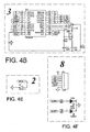
- the charger case 100 further comprises a display unit 8 provided thereon and electrically connected with the multi-battery charging module for displaying a charging status of the rechargeable battery.
- the display unit 8 may be embodied as a LCD display unit for graphically displaying the charging status by texts or simple figures.
- the display unit 8 can also be embodied as at least one LED for indicating the charging status by controlled illumination thereof, as shown in Fig. 1 of the drawings.
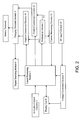
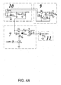
- the multi-battery charging module further comprises a DC input circuitry 10 electrically connecting with the electric input terminal 200 of the charger case 100, a voltage conversion circuitry 9 electrically connected with the DC input circuitry 10 and the central processing module 3, a charging terminals circuitry 5 electrically connected to the charging terminals 600 of the charger case 100, an activation control circuitry 2 electrically connected to the central processing module 3 for detecting presence of the rechargeable battery and activating the central processing module 3 when the rechargeable battery is electrically connecting with the charging terminals 600.
- the activation control circuitry 2 is preferably operated through a mechanical switch or a light-sensitive switch.
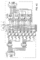
- the multi-battery charging module further comprises a digital searching module 6 electrically connected with the central process circuitry 3 and the charging terminals circuitry 5, and a current monitoring circuitry 11 electrically connected with a negative terminal of the recharging circuitry 7 and the central processing unit 3 through a regular R-C circuit for detecting a charging current of the rechargeable battery when it is being recharged by the recharging circuitry 7.
- the terminal rerouting circuitry comprises a negative connection circuitry 41 electrically connected with the charging terminals circuitry 5 and the central processing module 3, and a positive connection circuitry 42 electrically connected with the charging terminals circuitry 5 and the central processing module 3. Referring to Fig. 2 of the drawings, the negative terminal of the recharging circuitry 7 is electrically connected to the negative connection circuitry 41, while a positive terminal of the recharging circuitry 7 is electrically connected with the positive connection circuitry 42 and the DC input circuitry 10.
- the DC input circuitry 10 when the multi-battery charger of the present invention is electrically connected with an external DC power source, the DC input circuitry 10 is arranged transmit the DC to the recharging circuitry 7 and the voltage conversion circuitry 9.
- the voltage conversion circuitry 9 is arranged to convert the voltage of the transformed DC into a predetermined voltage for use by the central processing module 3 and the display unit 8. In other words, the voltage conversion circuitry 9 supplies the necessary electricity at the predetermined voltage to the display unit 8, and the central process circuitry 3 which then electrically activates and controls other circuitries within the multi-battery charging module.
- the operation of the present invention is as follows: first, a user has to fittedly dispose a rechargeable battery having two battery terminals (one of them is positive and another is negative) into one of the battery compartments 103 so that the two battery terminals electrically connects with at least one of the charging terminals 600. Then the user should electrically connect the electric input terminal 200 to an external DC power source.
- the externally acquired DC is divided and transmitted to the recharging circuitry 7 and the voltage conversion circuitry 9 which then further converts the externally acquired DC into the predetermined voltage and transmits the converted DC voltage to the central processing module 3 and the display unit 8 for supplying adequate electrical power to activate them.
- the activation control circuitry 2 is activated to activate a polarity detection process which is to be coordinated by the central processing module 3.
- the central processing module 3 When the central processing module 3 is electrically activated to carry out the polarity detection process, the central processing module 3 will first drives the negative connection circuitry 41 to electrically connect the negative terminal of the recharging circuitry 7 with one of the charging terminals 600 (first charging terminal 600) which is electrically connecting with one of the battery terminals. The central processing module 3 will then activate the digital searching module 6 to search and detect for a positive polarity among other charging terminals 600 which have not been electrically connected to the negative terminal of the recharging circuitry 7.
- the digital searching module 6 is arranged to send a feedback signal back to the central process module 3 which then drives the positive connection circuitry 42 to electrically connect the second charging terminals 600 with the positive terminal of the recharging circuitry 7.
- the central processing module 3 After the positive terminal and the negative terminal of the recharging circuitry 7 have been electrically connected to the two charging terminals 600 respectively (the first and the second charging terminals 600 respectively), the central processing module 3 signals the recharging circuitry 7 to start the tester charging process. At the same time, the central processing module 3 also activates the current monitoring circuitry 11 to detect a charging current and the voltage change of the rechargeable battery.
- the rechargeable battery is being properly recharged, i.e. when the positive battery terminal is electrically connected with the positive charging terminal 600 (second charging terminal 600) and the negative battery terminal is electrically connected with the negative charging terminal 600 (the first charging terminal 600), a recharging voltage pattern (a first recharging voltage pattern) representing a change of battery voltage with respect to charging current will be obtained.
- the central processing module 3 is programmed to positively recognize the recharging voltage pattern as being proper. The substantive charging process will now be actually started for fully recharging the rechargeable battery.
- the central processing module 3 then drive the positive connection circuitry 42 to electrically disconnect the charging terminal 600 (the second charging terminal 600) electrically connecting with the positive terminal of the recharging circuitry 7 and electrically reconnects the positive terminal of the recharging circuitry 7 with another charging terminal 600 (third charging terminal 600).
- the first and the third charging terminals 600 are electrically connected with the negative and the positive terminal of the recharging circuitry 7 respectively, a second recharging voltage pattern will be obtained which and compared with the predetermined reference recharging voltage pattern.
- this second recharging voltage pattern follows the reference recharging voltage pattern
- the central processing module 3 is programmed to positively recognize the second recharging voltage pattern as being proper.
- the charging process will now be continued until the rechargeable battery is fully charged. However, when the second recharging voltage pattern departs substantially from the reference voltage pattern, this means the rechargeable battery is also not properly charged.
- the above process continues with the second charging terminal 600 being replaced by a third charging terminal 600 of the charger case 100, and stops when the recharging voltage pattern substantially resembles the reference recharging voltage pattern.
- the central processing module 3 will then drive the negative connection circuitry 41 to electrically re-connect the negative terminal of the recharging circuitry 7 with one of the charging terminals 600 except the first charging terminal 600. Moreover, the central processing module 3 will then drive the positive connection circuitry 42 to electrically re-connect the positive terminal of the charging circuitry 7 with the first charging terminal 600 for obtaining the recharging voltage pattern.
- the recharging voltage pattern will then be compared with the reference recharging voltage for the purpose as described above. The above process continues until the recharging voltage pattern resembles the reference recharging voltage pattern. At that time, the substantive charging process will be initialed by the central processing module 3.
- the central processing module 3 will drive the display unit 8 to display an error message thereon.
- the error message may inform the user that the rechargeable battery is not properly disposed into the charging case 100.
- the central processing module 3 is arranged to initiate the substantive recharging process of the present invention.
- the central processing module 3 when the central processing module 3 initiates the substantive recharging process, it is arranged to send a Pulse-Width Modulation (PWM) signal to the recharging circuitry 7 for driving it to recharge the rechargeable battery at a predetermined charging current which is monitored by the current monitoring circuitry 11.
- PWM Pulse-Width Modulation
- the central processing module 3 In order to prevent overcharging of the rechargeable battery, the central processing module 3 must be able to obtain a real-time recharging voltage of the rechargeable battery. This can be accomplished by the following manner: the central processing module 3 will first drives the digital searching module 6 to electrically connect with the positive terminal of the rechargeable battery as detected to obtain real-time positive charging voltage, and then electrically connect with the negative terminal of the rechargeable battery as detected to obtain a real-time negative charging voltage. The real-time recharging voltage of the rechargeable battery is then obtained by subtracting the real-time positive charging voltage from the real-time negative charging voltage.
- PWM Pul
- the rechargeable battery is preferably embodied as a conventional lithium-ion battery with the maximum capacity being conventionally set at 0.1 ampere-hour (Ah).
- the charging current as detected by the current monitoring circuitry 11 will become smaller and smaller and the recharging voltage will increase over time
- the charging current eventually becomes stabilized and reaches a predetermined constant current.
- the real-time recharging voltage reaches a predetermined threshold which is substantially the same as the maximum capacity of the rechargeable battery, constant-voltage charging occurs and the charging current will drop and eventually reach the predetermined constant current.
- this constant current is conventionally set at 50mA, so that when the current monitoring circuitry 11 detects that the charging current stabilizes at around 50mA, the central processing circuitry 3 is pre-programmed to stop the substantive recharging process.
- the recharging process can be characterized as:
- the central processing circuitry 3 is programmed to stop the substantive charging process because the rechargeable battery is deemed to be fully charged.
- the multi-battery charger is adapted to recharge rechargeable battery containing one or two battery units.
- the central processing unit 3 is adapted to deactivate the recharging circuitry 7 and at the same time activate the display unit 8 to show a corresponding message signaling the user of the present invention to take away the rechargeable battery from the charger case 100.
- the present invention also provides a method of charging a rechargeable battery by a multi-battery charger comprising a plurality of charging terminals 600, a recharging circuitry 7, a central processing module 3, wherein the rechargeable battery has a first and a second battery terminal but unknown polarity, wherein the method comprises the steps of:
- Step (d) comprises the steps of:
- Step (g) comprises the steps of:
- Step (g) further comprises the step of:
Landscapes
- Engineering & Computer Science (AREA)
- Power Engineering (AREA)
- Charge And Discharge Circuits For Batteries Or The Like (AREA)
- Secondary Cells (AREA)
Applications Claiming Priority (2)
| Application Number | Priority Date | Filing Date | Title |
|---|---|---|---|
| CNA2006101273957A CN101150258A (zh) | 2006-09-18 | 2006-09-18 | 充电器 |
| US11/773,961 US7898213B2 (en) | 2006-09-18 | 2007-07-06 | Multi-battery charger |
Publications (2)
| Publication Number | Publication Date |
|---|---|
| EP1901410A2 true EP1901410A2 (fr) | 2008-03-19 |
| EP1901410A3 EP1901410A3 (fr) | 2013-05-15 |
Family
ID=38537821
Family Applications (1)
| Application Number | Title | Priority Date | Filing Date |
|---|---|---|---|
| EP07017415.6A Withdrawn EP1901410A3 (fr) | 2006-09-18 | 2007-09-05 | Chargeur de plusieurs batteries |
Country Status (1)
| Country | Link |
|---|---|
| EP (1) | EP1901410A3 (fr) |
Cited By (1)
| Publication number | Priority date | Publication date | Assignee | Title |
|---|---|---|---|---|
| CN114447459A (zh) * | 2022-01-04 | 2022-05-06 | 深圳供电局有限公司 | 混合型电池 |
Families Citing this family (1)
| Publication number | Priority date | Publication date | Assignee | Title |
|---|---|---|---|---|
| KR101783659B1 (ko) | 2016-02-17 | 2017-10-24 | 김영조 | 휴대단말용 보조배터리팩 멀티크래들 장치 |
Family Cites Families (5)
| Publication number | Priority date | Publication date | Assignee | Title |
|---|---|---|---|---|
| GB2240439A (en) * | 1989-09-08 | 1991-07-31 | Link Sedan Limited | Battery charger |
| US5352969A (en) * | 1991-05-30 | 1994-10-04 | Black & Decker Inc. | Battery charging system having logarithmic analog-to-digital converter with automatic scaling of analog signal |
| US5780991A (en) * | 1996-07-26 | 1998-07-14 | Telxon Corporation | Multiple station charging apparatus with single charging power supply for parallel charging |
| US6610941B2 (en) * | 2001-10-02 | 2003-08-26 | Jdp Innovations Inc. | Battery size detector for a battery charger |
| US6630812B1 (en) * | 2002-05-02 | 2003-10-07 | Lsi Logic Corporation | Standard high volume battery charger |
-
2007
- 2007-09-05 EP EP07017415.6A patent/EP1901410A3/fr not_active Withdrawn
Cited By (2)
| Publication number | Priority date | Publication date | Assignee | Title |
|---|---|---|---|---|
| CN114447459A (zh) * | 2022-01-04 | 2022-05-06 | 深圳供电局有限公司 | 混合型电池 |
| CN114447459B (zh) * | 2022-01-04 | 2024-06-14 | 深圳供电局有限公司 | 混合型电池 |
Also Published As
| Publication number | Publication date |
|---|---|
| EP1901410A3 (fr) | 2013-05-15 |
Similar Documents
| Publication | Publication Date | Title |
|---|---|---|
| US7898213B2 (en) | Multi-battery charger | |
| US12421928B2 (en) | Multifunctional battery booster | |
| US6583601B2 (en) | Portable battery charger for a mobile device | |
| KR101485665B1 (ko) | 셀 밸런싱 회로 및 이를 이용한 셀 밸런싱 방법 | |
| CA3021653C (fr) | Systeme et procede de detection d'etat de batterie | |
| US7183748B1 (en) | Electric charger and power supply device for portable terminal | |
| US8860371B2 (en) | Series battery charger with the function of separate detection | |
| AU2007221261B2 (en) | Power supply for battery powered devices | |
| US20130049675A1 (en) | Output connector equipped battery pack, battery-pack-and-battery-driven-device system, and charging method by using battery pack | |
| EP3576213A1 (fr) | Bloc-batterie, procédé de contrôle de charge du bloc-batterie, et véhicule comprenant le bloc-batterie | |
| US20080238357A1 (en) | Ultra fast battery charger with battery sensing | |
| EP3972072B1 (fr) | Adaptateur, bloc-batterie et combinaison d'adaptateurs | |
| EP2578069A2 (fr) | Module d'alimentation pour dispositifs portables | |
| JP2017112802A (ja) | 充放電ユニット、及びこれを用いた電源ユニット、充放電システム、電源システム | |
| EP2561593A2 (fr) | Chargeur incorporé | |
| KR101673533B1 (ko) | 배터리 셀의 순차 방전이 가능한 전원 공급 장치 | |
| EP1901410A2 (fr) | Chargeur de plusieurs batteries | |
| US11689036B2 (en) | Free voltage adapter for charging | |
| CN113574766B (zh) | 用于供电的模块化设备 | |
| CN109474047B (zh) | 一种背夹电池 | |
| WO2011016791A1 (fr) | Adaptateur de puissance doté dun circuit à économie dénergie | |
| JPH09322415A (ja) | 二次電池の充電方式 |
Legal Events
| Date | Code | Title | Description |
|---|---|---|---|
| PUAI | Public reference made under article 153(3) epc to a published international application that has entered the european phase |
Free format text: ORIGINAL CODE: 0009012 |
|
| 17P | Request for examination filed |
Effective date: 20070905 |
|
| AK | Designated contracting states |
Kind code of ref document: A2 Designated state(s): AT BE BG CH CY CZ DE DK EE ES FI FR GB GR HU IE IS IT LI LT LU LV MC MT NL PL PT RO SE SI SK TR |
|
| AX | Request for extension of the european patent |
Extension state: AL BA HR MK YU |
|
| PUAL | Search report despatched |
Free format text: ORIGINAL CODE: 0009013 |
|
| AK | Designated contracting states |
Kind code of ref document: A3 Designated state(s): AT BE BG CH CY CZ DE DK EE ES FI FR GB GR HU IE IS IT LI LT LU LV MC MT NL PL PT RO SE SI SK TR |
|
| AX | Request for extension of the european patent |
Extension state: AL BA HR MK RS |
|
| RIC1 | Information provided on ipc code assigned before grant |
Ipc: H02J 7/00 20060101AFI20130409BHEP |
|
| AKX | Designation fees paid |
Designated state(s): AT BE BG CH CY CZ DE DK EE ES FI FR GB GR HU IE IS IT LI LT LU LV MC MT NL PL PT RO SE SI SK TR |
|
| STAA | Information on the status of an ep patent application or granted ep patent |
Free format text: STATUS: THE APPLICATION IS DEEMED TO BE WITHDRAWN |
|
| 18D | Application deemed to be withdrawn |
Effective date: 20131116 |