EP1901411A2 - Procédé destiné à la commande d'un moteur d'un outil à pile - Google Patents
Procédé destiné à la commande d'un moteur d'un outil à pile Download PDFInfo
- Publication number
- EP1901411A2 EP1901411A2 EP07114997A EP07114997A EP1901411A2 EP 1901411 A2 EP1901411 A2 EP 1901411A2 EP 07114997 A EP07114997 A EP 07114997A EP 07114997 A EP07114997 A EP 07114997A EP 1901411 A2 EP1901411 A2 EP 1901411A2
- Authority
- EP
- European Patent Office
- Prior art keywords
- motor
- battery voltage
- electronic device
- switch
- battery
- Prior art date
- Legal status (The legal status is an assumption and is not a legal conclusion. Google has not performed a legal analysis and makes no representation as to the accuracy of the status listed.)
- Granted
Links
Images


Classifications
-
- H—ELECTRICITY
- H02—GENERATION; CONVERSION OR DISTRIBUTION OF ELECTRIC POWER
- H02J—ELECTRIC POWER NETWORKS; CIRCUIT ARRANGEMENTS OR SYSTEMS FOR SUPPLYING OR DISTRIBUTING ELECTRIC POWER; SYSTEMS FOR STORING ELECTRIC ENERGY
- H02J7/00—Circuit arrangements for charging or discharging batteries or for supplying loads from batteries
- H02J7/60—Circuit arrangements for charging or discharging batteries or for supplying loads from batteries including safety or protection arrangements
- H02J7/663—Circuit arrangements for charging or discharging batteries or for supplying loads from batteries including safety or protection arrangements using battery or load disconnect circuits
-
- H—ELECTRICITY
- H02—GENERATION; CONVERSION OR DISTRIBUTION OF ELECTRIC POWER
- H02J—ELECTRIC POWER NETWORKS; CIRCUIT ARRANGEMENTS OR SYSTEMS FOR SUPPLYING OR DISTRIBUTING ELECTRIC POWER; SYSTEMS FOR STORING ELECTRIC ENERGY
- H02J7/00—Circuit arrangements for charging or discharging batteries or for supplying loads from batteries
- H02J7/855—Circuit arrangements for charging or discharging batteries or for supplying loads from batteries with circuits adapted for supplying loads from the battery
-
- H—ELECTRICITY
- H02—GENERATION; CONVERSION OR DISTRIBUTION OF ELECTRIC POWER
- H02J—ELECTRIC POWER NETWORKS; CIRCUIT ARRANGEMENTS OR SYSTEMS FOR SUPPLYING OR DISTRIBUTING ELECTRIC POWER; SYSTEMS FOR STORING ELECTRIC ENERGY
- H02J7/00—Circuit arrangements for charging or discharging batteries or for supplying loads from batteries
- H02J7/90—Regulation of charging or discharging current or voltage
- H02J7/96—Regulation of charging or discharging current or voltage in response to battery voltage
-
- H—ELECTRICITY
- H02—GENERATION; CONVERSION OR DISTRIBUTION OF ELECTRIC POWER
- H02P—CONTROL OR REGULATION OF ELECTRIC MOTORS, ELECTRIC GENERATORS OR DYNAMO-ELECTRIC CONVERTERS; CONTROLLING TRANSFORMERS, REACTORS OR CHOKE COILS
- H02P7/00—Arrangements for regulating or controlling the speed or torque of electric DC motors
- H02P7/06—Arrangements for regulating or controlling the speed or torque of electric DC motors for regulating or controlling an individual DC dynamo-electric motor by varying field or armature current
- H02P7/18—Arrangements for regulating or controlling the speed or torque of electric DC motors for regulating or controlling an individual DC dynamo-electric motor by varying field or armature current by master control with auxiliary power
- H02P7/24—Arrangements for regulating or controlling the speed or torque of electric DC motors for regulating or controlling an individual DC dynamo-electric motor by varying field or armature current by master control with auxiliary power using discharge tubes or semiconductor devices
- H02P7/28—Arrangements for regulating or controlling the speed or torque of electric DC motors for regulating or controlling an individual DC dynamo-electric motor by varying field or armature current by master control with auxiliary power using discharge tubes or semiconductor devices using semiconductor devices
- H02P7/285—Arrangements for regulating or controlling the speed or torque of electric DC motors for regulating or controlling an individual DC dynamo-electric motor by varying field or armature current by master control with auxiliary power using discharge tubes or semiconductor devices using semiconductor devices controlling armature supply only
- H02P7/29—Arrangements for regulating or controlling the speed or torque of electric DC motors for regulating or controlling an individual DC dynamo-electric motor by varying field or armature current by master control with auxiliary power using discharge tubes or semiconductor devices using semiconductor devices controlling armature supply only using pulse modulation
-
- Y—GENERAL TAGGING OF NEW TECHNOLOGICAL DEVELOPMENTS; GENERAL TAGGING OF CROSS-SECTIONAL TECHNOLOGIES SPANNING OVER SEVERAL SECTIONS OF THE IPC; TECHNICAL SUBJECTS COVERED BY FORMER USPC CROSS-REFERENCE ART COLLECTIONS [XRACs] AND DIGESTS
- Y10—TECHNICAL SUBJECTS COVERED BY FORMER USPC
- Y10S—TECHNICAL SUBJECTS COVERED BY FORMER USPC CROSS-REFERENCE ART COLLECTIONS [XRACs] AND DIGESTS
- Y10S388/00—Electricity: motor control systems
- Y10S388/935—Specific application:
- Y10S388/937—Hand tool
Definitions
- the invention relates to a method for controlling a motor of a battery-powered tool device, such as a hand-held circular saw, according to the preamble of patent claim 1, and a control device for carrying out the method according to the preamble of the subordinate patent claim.
- the motor drives a tool of the tool device.
- all the electronics are usually disconnected from the battery with the motor switch to prevent the battery from being discharged when not in use.
- the method for controlling the motor of the power tool is usually designed so that the control electronics shuts off the tool or the motor falls below a certain supply voltage to prevent damage to the motor or the electrical components. The undervoltage shutdown takes place z. B. when the battery is discharged or defective.
- Such an undervoltage shutdown is z. B. from the DE 36 11 884 A1 known in a battery-powered hand tool.
- a switch-off relay controlled by a flip-flop circuit is provided there, the flip-flop circuit being controllable by an undervoltage monitor.
- the switch-off relay can be connected to voltage via a main switch to put the hand tool into operation.
- the switch-off relay has a changeover switch, which short-circuits the motor when the switch-off relay drops, so that it is slowed down when the main switch is released again or when the undervoltage monitor causes an undervoltage switch-off via the flip-flop circuit.
- the present invention has for its object to provide a control method that avoids the disadvantages mentioned.
- the object is achieved in that in a second step, which follows an initialization of the electronic device or the control electronics, a continuous monitoring of the motor current and the battery voltage takes place and that in a third step, which alternates with the second step, a continuous Comparison of the battery voltage with a stored in a memory of the electronic device limit occurs.
- a further method step may be provided for the case that the off position of a motor switch is detected by the electronic device, wherein in this further step of the method, a continuous monitoring of the battery voltage for a defined period.
- the motor switch is actuated again, the motor can be switched on without loss of time since the electronic device does not need to be initialized first. A restart of the motor of the power tool on immediate restart after switching off the motor switch is therefore possible.
- the limit for the battery voltage in a range of 5 V up to 70% of the rated voltage of the usable battery creating a safe control of the power semiconductors, and the circuit breaker, such. B. a MOSFET, is guaranteed.
- the limit is thus between 5 V and 16.8 V.
- the object is achieved by a tool device having a control device for carrying out the method in one of the abovementioned embodiments.
- a control device for carrying out the method in one of the abovementioned embodiments.
- at least the second, the third and the further step of the method are carried out in a microcontroller belonging to the electronic device.
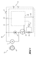
- FIG. 1 shows the control device 20 of a tool device 10, not shown in detail, in the form of a portable circular saw with a motor 11, via which a disk-shaped tool 12 in the form of a saw blade with a rated power can be driven.
- the motor 11 is switched on and off by means of a motor switch 21 of the control device 20.
- the motor switch 21 can be adjusted between an illustrated off position and an on position shown in dash-dotted lines. In this case, a battery voltage generated by a battery 13 is applied to the motor 11 and the control device 20 in the on position.
- the control device 20 has an electronic device 22 which comprises a protective diode 24, a shunt in the form of a low-resistance resistor 25, an electronic power switch 26, an operational amplifier 27 and a control unit 28.
- the control unit 28 also has a microcontroller not shown in the figure.
- a motor current IM occurring during operation on the motor 11 (see FIGS. 2 to 5) is permanently determined and evaluated by the control unit 28 with the microcontroller.
- the battery voltage UB (see FIGS. 2 to 5) is determined via the path 23 and evaluated by the control unit 28 with the microcontroller. Via the line 29, the control unit 28 is connected to ground.
- the inventive control method is shown in the flowchart in Fig. 2. Accordingly, upon actuation of the engine switch 21 in a first step 31, first the control unit 28 is initialized with the microprocessor and then the motor 11 is turned on. Thereafter, in a continuously repeated second step 32, a monitoring of the motor current IM and the battery voltage UB. The battery voltage UB is compared in a likewise continuously repeated third step 33 with a stored in a memory of the control unit 28 limit value GW.
- the limit GW is in a range of 5 V up to 70% of the rated voltage of the usable battery.
- the controller 28 recognizes that the motor switch 21 has not been transferred to an off position (solid line in FIG. 1), but rather that the battery 13 is defective or discharged. From the control device 28, a low voltage cutoff of the motor 11 is then made in a fourth step 34, wherein the electronic device 22 is still turned on until a manual transfer of the engine switch 11 in the off position.
- the shutdown is z. B. made by the electronic circuit breaker 26, the z. B. is designed as a MOSFET.
- the controller 28 recognizes in a fifth step 35 that the motor switch 21 is in an off position (solid line in Fig. 1) has been transferred. Thereafter, in a sixth step 36, the battery voltage UB during a period T, the z. B. 2 to 5 seconds is monitored. Does not increase the battery voltage UB within the period T by re-actuation of the motor switch 21, then the electronic device 22 is placed in a seventh step 37 in an off state.
- the electronic device 22 Upon renewed operation, the electronic device 22 is then initially initialized again in a first step 31, and then the motor 11 is switched on.
- the control method then jumps directly to the second step 32 and the third step 33, the continuous monitoring of the battery voltage UB and the motor current IM and the continuous comparison of the battery voltage UB with the limit GW.
- the power supply of the controller 28 during the period T can z.
- the control unit 28 via capacitors, which are present in the control device 28 or on the still in rotation motor 11, the control unit 28 is sufficiently supplied with energy by the induced voltage from the rotation of the voltage for the operation of the microcontroller.
- the length of the period T is preferably defined by the time during which a current is still available for the supply of the control unit, but it can also be defined by the microcontroller.
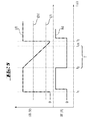
- FIGS. 3 to 5 show the current and voltage profiles for various operating situations, with the aid of which the control method according to the invention is explained in greater detail.
- the measured battery voltage UB in volts (V) and the measured motor current IM in amperes (A) are plotted on the ordinates of the diagrams.
- the time t is plotted in seconds.
- Fig. 3 the course of the motor current IM and the battery voltage UB is shown in the event that the battery is deflated or defective.
- the user actuates the motor switch 21 and transfers it to the on position (shown in dashed lines in FIG. 1).
- the battery voltage UB rises immediately while the motor current IM increases in a time-delayed manner, since the electronic device 22 first had to be initialized in the first step 31 of the control method.
- the continuous monitoring of the battery voltage UB and the motor current IM and the continuous comparison of the battery voltage UB with the limit GW.
- the battery voltage UB has dropped below the limit value GW, while the motor current IM is still present at this second time t 2 .
- the control unit 28 detects a discharge or a defect of the battery 13 and initiates in a fourth step 34, the undervoltage shutdown, in which the motor 11 is turned off.
- the electronic device 22, however, remains up to the manual Transferring the motor switch 11 is turned on in the off position. After switching off the motor 11, therefore, the battery voltage UB again rises above the limit value GW.
- Fig. 4 the course of the motor current IM and the battery voltage UB is shown in the event that the power tool 10 is turned off via the motor switch 21 and is turned on again within the period T.
- the user actuates the motor switch 21 and places it in the on position (shown in dashed lines in FIG. 1), the steps 31, 32 and 33 of the control method proceeding as described above.
- the motor switch 21 is now transferred by the user to the off position (see FIG. 1).
- the battery voltage UB drops slowly, while the motor current IM goes back almost to zero.
- the control unit 28 detects in a fifth method step 35 that the motor switch 21 has been transferred to the off position and now continuously monitors the battery voltage UB in the sixth step 36 during the period T. At the third time t 3 , the battery voltage UB rises within the period T jumped again. In an eighth step 38, the motor 11 is now switched on via the electronic device 22 again.
- the control method jumps, as already described, subsequently directly to the second step 32 and the third step 33, the continuous monitoring of the battery voltage UB and the motor current IM and the continuous comparison of the battery voltage UB with the limit GW.
- the motor switch 21 is operated again and transferred to the on position.
- the battery voltage UB rises immediately while the motor current IM increases in a time-delayed manner, since the electronic device 22 first had to be initialized in the first step 31 of the control method.
- the second and third steps 32 and 33 of the control method are running, the continuous monitoring of the battery voltage UB and of the motor current IM and the continuous comparison of the battery voltage UB with the limit value GW.
- the time period T could also be stored in the memory of the microcontroller or the control unit 28 and the transfer of the electronic device 22 in the off state in the seventh step 37 take the microcontroller.
Landscapes
- Engineering & Computer Science (AREA)
- Power Engineering (AREA)
- Control Of Electric Motors In General (AREA)
Applications Claiming Priority (1)
| Application Number | Priority Date | Filing Date | Title |
|---|---|---|---|
| DE102006000439.6A DE102006000439B4 (de) | 2006-09-04 | 2006-09-04 | Verfahren zur Steuerung eines Motors eines akkubetriebenen Werkzeuggerätes |
Publications (3)
| Publication Number | Publication Date |
|---|---|
| EP1901411A2 true EP1901411A2 (fr) | 2008-03-19 |
| EP1901411A3 EP1901411A3 (fr) | 2013-03-20 |
| EP1901411B1 EP1901411B1 (fr) | 2015-09-16 |
Family
ID=38729067
Family Applications (1)
| Application Number | Title | Priority Date | Filing Date |
|---|---|---|---|
| EP07114997.5A Active EP1901411B1 (fr) | 2006-09-04 | 2007-08-27 | Procédé destiné à la commande d'un moteur d'un outil à pile |
Country Status (4)
| Country | Link |
|---|---|
| US (1) | US7750587B2 (fr) |
| EP (1) | EP1901411B1 (fr) |
| CN (1) | CN101197499B (fr) |
| DE (1) | DE102006000439B4 (fr) |
Families Citing this family (11)
| Publication number | Priority date | Publication date | Assignee | Title |
|---|---|---|---|---|
| JP5463014B2 (ja) * | 2008-07-04 | 2014-04-09 | 株式会社マキタ | 電動工具 |
| US20110060737A1 (en) * | 2009-08-03 | 2011-03-10 | Jonathan Cardella | System for Matching Procedure Characteristics to Professional Experience |
| DE102010045550A1 (de) * | 2010-09-16 | 2012-03-22 | Festool Gmbh | Steuerung und Verfahren für eine elektrische Hand-Werkzeugmaschine |
| JP2012130980A (ja) * | 2010-12-21 | 2012-07-12 | Makita Corp | コードレス電動工具 |
| JP2014017952A (ja) * | 2012-07-06 | 2014-01-30 | Hitachi Koki Co Ltd | 背負式電源 |
| DE102017103005A1 (de) * | 2017-02-15 | 2018-08-16 | Metabowerke Gmbh | Überlastschutz einer akkubetriebenen Elektrowerkzeugmaschine |
| EP3379019B1 (fr) * | 2017-03-24 | 2019-09-04 | Techtronic Outdoor Products Technology Limited | Appareil d'excavation |
| US10868431B2 (en) | 2018-01-16 | 2020-12-15 | Cisco Technology, Inc. | Battery charging cut-off circuit |
| CN112366656A (zh) * | 2020-11-10 | 2021-02-12 | 珠海格力电器股份有限公司 | 电机控制方法、装置、电机设备及用电设备 |
| JP2023000199A (ja) * | 2021-06-17 | 2023-01-04 | 株式会社デンソー | アクチュエータ制御装置 |
| DE102023202161A1 (de) * | 2023-03-10 | 2024-09-12 | Festool Gmbh | Steuerungseinheit für eine Antriebseinheit einer Hand-Werkzeugmaschine, Antriebseinheit, Hand-Werkzeugmaschine und Verfahren zum Betrieb einer Hand-Werkzeugmaschine |
Family Cites Families (10)
| Publication number | Priority date | Publication date | Assignee | Title |
|---|---|---|---|---|
| DE3611884A1 (de) | 1986-04-09 | 1987-10-22 | Fein C & E | Akkubetriebenes handwerkzeug, insbesondere schrauber |
| US5014793A (en) * | 1989-04-10 | 1991-05-14 | Measurement Specialties, Inc. | Variable speed DC motor controller apparatus particularly adapted for control of portable-power tools |
| DE4123105A1 (de) | 1991-07-09 | 1993-01-14 | Brose Fahrzeugteile | Verfahren und vorrichtung zur regelung der ansteuerleistung elektrischer verbraucher |
| CZ408297A3 (cs) | 1997-12-17 | 2000-08-16 | Grigorij Ing. Dvorský | Způsob řízení modelářských elektromotorů inteligentním regulátorem otáček |
| CN2336506Y (zh) * | 1998-07-03 | 1999-09-01 | 陈宝中 | 一种充电机用控制装置 |
| JP3506916B2 (ja) * | 1998-07-03 | 2004-03-15 | 株式会社マキタ | 充電装置 |
| US6324339B1 (en) * | 1999-11-29 | 2001-11-27 | Eveready Battery Company, Inc. | Battery pack including input and output waveform modification capability |
| US6696814B2 (en) * | 2001-07-09 | 2004-02-24 | Tyco Electronics Corporation | Microprocessor for controlling the speed and frequency of a motor shaft in a power tool |
| US7133601B2 (en) * | 2003-02-18 | 2006-11-07 | Black & Decker Inc. | Amperage control for protection of battery over current in power tools |
| US7969116B2 (en) * | 2005-04-04 | 2011-06-28 | Hitachi Koki Co., Ltd. | Power pack and cordless power tool having the same |
-
2006
- 2006-09-04 DE DE102006000439.6A patent/DE102006000439B4/de active Active
-
2007
- 2007-08-27 EP EP07114997.5A patent/EP1901411B1/fr active Active
- 2007-08-29 US US11/897,284 patent/US7750587B2/en active Active
- 2007-09-03 CN CN2007101469492A patent/CN101197499B/zh active Active
Also Published As
| Publication number | Publication date |
|---|---|
| CN101197499A (zh) | 2008-06-11 |
| US20080106225A1 (en) | 2008-05-08 |
| EP1901411A3 (fr) | 2013-03-20 |
| CN101197499B (zh) | 2012-06-06 |
| EP1901411B1 (fr) | 2015-09-16 |
| DE102006000439A1 (de) | 2008-03-13 |
| US7750587B2 (en) | 2010-07-06 |
| DE102006000439B4 (de) | 2020-07-30 |
Similar Documents
| Publication | Publication Date | Title |
|---|---|---|
| EP1901411B1 (fr) | Procédé destiné à la commande d'un moteur d'un outil à pile | |
| EP1247431B1 (fr) | Dispositif et procede pour commander des moyens d'exploitation pour au moins un moyen d'eclairage electrique | |
| DE102008031270B4 (de) | Steuergerät zur Absicherung eines Ausfalls einer Schaltvorrichtung bei Spannungswandlern in Kraftfahrzeugen | |
| DE1956955A1 (de) | Rueckkopplungssteuersystem fuer die Folgeschaltung von Motoren | |
| DE2326027A1 (de) | Schraubenziehergeraet | |
| DE3335237A1 (de) | Verfahren und vorrichtung zur regelung eines elektromotors, bei welchem die drehzahl im lastfreien leerlaufbetrieb automatisch abgesenkt wird | |
| DE3229306A1 (de) | Bohrmaschine mit elektromagnetischer grundeinheit | |
| WO2014030062A2 (fr) | Appareil de lumière de secours | |
| DE102004008147A1 (de) | Bordseitiges Stromversorgungssystem | |
| EP2615297B1 (fr) | Réseau de bord de véhicule automobile et procédé de fonctionnement d'un réseau de bord de véhicule automobile | |
| DE102006034837B4 (de) | Maschinenanlasser und Maschinenstartverfahren | |
| EP3711133A1 (fr) | Procédé de démarrage autonome d'un dispositif d'alimentation en énergie, onduleur bidirectionnel et dispositif d'alimentation en énergie doté d'un onduleur bidirectionnel | |
| DE102005045309A1 (de) | Sauggerät | |
| DE19915973C1 (de) | Verfahren zur Regelung der Bordnetzspannung eines Kraftfahrzeugs | |
| EP0862810B1 (fr) | Mecanisme d'entrainement pour porte electrique | |
| DE4201005A1 (de) | Aussetzerfreie getaktete bremsschaltung | |
| DE10248415A1 (de) | Stromversorgungsschaltung für ein Kraftfahrzeug mit zwei unterschiedlichen Verbraucherspannungen | |
| WO2013124031A2 (fr) | Appareil de démarrage du compresseur d'une centrifugeuse de refroidissement | |
| WO2009068212A1 (fr) | Dispositif de commande et procédé de démarrage d'un moteur à combustion interne | |
| DE10260621B4 (de) | Anlasservorrichtung zum Ankurbeln einer Brennkraftmaschine | |
| EP2145512B1 (fr) | Circuit et procédé permettant de faire fonctionner au moins une lampe à décharge | |
| EP2163337B1 (fr) | Dispositif de soudage ou de brasage à consommation réduite | |
| EP1825529B1 (fr) | Circuit electrique pour reguler un element piezo-electrique, notamment d'un systeme d'injection de carburant d'automobile | |
| DE102004042256A1 (de) | Gleichspannungszwischenkreis | |
| DE4437351B4 (de) | Verfahren zum Abgleichen einer Schutzschaltung für einen Elektromotor |
Legal Events
| Date | Code | Title | Description |
|---|---|---|---|
| PUAI | Public reference made under article 153(3) epc to a published international application that has entered the european phase |
Free format text: ORIGINAL CODE: 0009012 |
|
| AK | Designated contracting states |
Kind code of ref document: A2 Designated state(s): AT BE BG CH CY CZ DE DK EE ES FI FR GB GR HU IE IS IT LI LT LU LV MC MT NL PL PT RO SE SI SK TR |
|
| AX | Request for extension of the european patent |
Extension state: AL BA HR MK YU |
|
| PUAL | Search report despatched |
Free format text: ORIGINAL CODE: 0009013 |
|
| AK | Designated contracting states |
Kind code of ref document: A3 Designated state(s): AT BE BG CH CY CZ DE DK EE ES FI FR GB GR HU IE IS IT LI LT LU LV MC MT NL PL PT RO SE SI SK TR |
|
| AX | Request for extension of the european patent |
Extension state: AL BA HR MK RS |
|
| RIC1 | Information provided on ipc code assigned before grant |
Ipc: H02P 7/29 20060101ALI20130208BHEP Ipc: H02J 7/00 20060101AFI20130208BHEP |
|
| 17P | Request for examination filed |
Effective date: 20130920 |
|
| RBV | Designated contracting states (corrected) |
Designated state(s): AT BE BG CH CY CZ DE DK EE ES FI FR GB GR HU IE IS IT LI LT LU LV MC MT NL PL PT RO SE SI SK TR |
|
| AKX | Designation fees paid |
Designated state(s): CH DE FR GB IT LI SE |
|
| 17Q | First examination report despatched |
Effective date: 20131126 |
|
| GRAP | Despatch of communication of intention to grant a patent |
Free format text: ORIGINAL CODE: EPIDOSNIGR1 |
|
| INTG | Intention to grant announced |
Effective date: 20150327 |
|
| GRAS | Grant fee paid |
Free format text: ORIGINAL CODE: EPIDOSNIGR3 |
|
| GRAA | (expected) grant |
Free format text: ORIGINAL CODE: 0009210 |
|
| AK | Designated contracting states |
Kind code of ref document: B1 Designated state(s): CH DE FR GB IT LI SE |
|
| REG | Reference to a national code |
Ref country code: GB Ref legal event code: FG4D Free format text: NOT ENGLISH |
|
| REG | Reference to a national code |
Ref country code: CH Ref legal event code: EP |
|
| REG | Reference to a national code |
Ref country code: DE Ref legal event code: R096 Ref document number: 502007014224 Country of ref document: DE |
|
| REG | Reference to a national code |
Ref country code: SE Ref legal event code: TRGR |
|
| REG | Reference to a national code |
Ref country code: DE Ref legal event code: R097 Ref document number: 502007014224 Country of ref document: DE |
|
| REG | Reference to a national code |
Ref country code: FR Ref legal event code: PLFP Year of fee payment: 10 |
|
| PLBE | No opposition filed within time limit |
Free format text: ORIGINAL CODE: 0009261 |
|
| STAA | Information on the status of an ep patent application or granted ep patent |
Free format text: STATUS: NO OPPOSITION FILED WITHIN TIME LIMIT |
|
| 26N | No opposition filed |
Effective date: 20160617 |
|
| REG | Reference to a national code |
Ref country code: FR Ref legal event code: PLFP Year of fee payment: 11 |
|
| REG | Reference to a national code |
Ref country code: FR Ref legal event code: PLFP Year of fee payment: 12 |
|
| P01 | Opt-out of the competence of the unified patent court (upc) registered |
Effective date: 20230830 |
|
| PGFP | Annual fee paid to national office [announced via postgrant information from national office to epo] |
Ref country code: DE Payment date: 20240821 Year of fee payment: 18 |
|
| PGFP | Annual fee paid to national office [announced via postgrant information from national office to epo] |
Ref country code: GB Payment date: 20240823 Year of fee payment: 18 |
|
| PGFP | Annual fee paid to national office [announced via postgrant information from national office to epo] |
Ref country code: FR Payment date: 20240828 Year of fee payment: 18 |
|
| PGFP | Annual fee paid to national office [announced via postgrant information from national office to epo] |
Ref country code: CH Payment date: 20240901 Year of fee payment: 18 |
|
| PGFP | Annual fee paid to national office [announced via postgrant information from national office to epo] |
Ref country code: IT Payment date: 20240827 Year of fee payment: 18 Ref country code: SE Payment date: 20240821 Year of fee payment: 18 |
|
| REG | Reference to a national code |
Ref country code: DE Ref legal event code: R119 Ref document number: 502007014224 Country of ref document: DE |
|
| REG | Reference to a national code |
Ref country code: CH Ref legal event code: H13 Free format text: ST27 STATUS EVENT CODE: U-0-0-H10-H13 (AS PROVIDED BY THE NATIONAL OFFICE) Effective date: 20260324 |
|
| PG25 | Lapsed in a contracting state [announced via postgrant information from national office to epo] |
Ref country code: CH Free format text: LAPSE BECAUSE OF NON-PAYMENT OF DUE FEES Effective date: 20250831 |