EP1901412B1 - System und Verfahren zur Batterieverwaltung - Google Patents
System und Verfahren zur Batterieverwaltung Download PDFInfo
- Publication number
- EP1901412B1 EP1901412B1 EP07115323.3A EP07115323A EP1901412B1 EP 1901412 B1 EP1901412 B1 EP 1901412B1 EP 07115323 A EP07115323 A EP 07115323A EP 1901412 B1 EP1901412 B1 EP 1901412B1
- Authority
- EP
- European Patent Office
- Prior art keywords
- voltage
- output voltage
- effective gain
- battery
- parking
- Prior art date
- Legal status (The legal status is an assumption and is not a legal conclusion. Google has not performed a legal analysis and makes no representation as to the accuracy of the status listed.)
- Ceased
Links
Images


Classifications
-
- B—PERFORMING OPERATIONS; TRANSPORTING
- B60—VEHICLES IN GENERAL
- B60L—PROPULSION OF ELECTRICALLY-PROPELLED VEHICLES; SUPPLYING ELECTRIC POWER FOR AUXILIARY EQUIPMENT OF ELECTRICALLY-PROPELLED VEHICLES; ELECTRODYNAMIC BRAKE SYSTEMS FOR VEHICLES IN GENERAL; MAGNETIC SUSPENSION OR LEVITATION FOR VEHICLES; MONITORING OPERATING VARIABLES OF ELECTRICALLY-PROPELLED VEHICLES; ELECTRIC SAFETY DEVICES FOR ELECTRICALLY-PROPELLED VEHICLES
- B60L50/00—Electric propulsion with power supplied within the vehicle
- B60L50/50—Electric propulsion with power supplied within the vehicle using propulsion power supplied by batteries or fuel cells
-
- H—ELECTRICITY
- H02—GENERATION; CONVERSION OR DISTRIBUTION OF ELECTRIC POWER
- H02J—ELECTRIC POWER NETWORKS; CIRCUIT ARRANGEMENTS OR SYSTEMS FOR SUPPLYING OR DISTRIBUTING ELECTRIC POWER; SYSTEMS FOR STORING ELECTRIC ENERGY
- H02J7/00—Circuit arrangements for charging or discharging batteries or for supplying loads from batteries
- H02J7/14—Circuit arrangements for charging or discharging batteries or for supplying loads from batteries for charging batteries from dynamo-electric generators driven at varying speed, e.g. on vehicle
- H02J7/1423—Circuit arrangements for charging or discharging batteries or for supplying loads from batteries for charging batteries from dynamo-electric generators driven at varying speed, e.g. on vehicle with multiple batteries
-
- B—PERFORMING OPERATIONS; TRANSPORTING
- B60—VEHICLES IN GENERAL
- B60L—PROPULSION OF ELECTRICALLY-PROPELLED VEHICLES; SUPPLYING ELECTRIC POWER FOR AUXILIARY EQUIPMENT OF ELECTRICALLY-PROPELLED VEHICLES; ELECTRODYNAMIC BRAKE SYSTEMS FOR VEHICLES IN GENERAL; MAGNETIC SUSPENSION OR LEVITATION FOR VEHICLES; MONITORING OPERATING VARIABLES OF ELECTRICALLY-PROPELLED VEHICLES; ELECTRIC SAFETY DEVICES FOR ELECTRICALLY-PROPELLED VEHICLES
- B60L3/00—Electric devices on electrically-propelled vehicles for safety purposes; Monitoring operating variables, e.g. speed, deceleration or energy consumption
- B60L3/0023—Detecting, eliminating, remedying or compensating for drive train abnormalities, e.g. failures within the drive train
- B60L3/0038—Detecting, eliminating, remedying or compensating for drive train abnormalities, e.g. failures within the drive train relating to sensors
-
- B—PERFORMING OPERATIONS; TRANSPORTING
- B60—VEHICLES IN GENERAL
- B60L—PROPULSION OF ELECTRICALLY-PROPELLED VEHICLES; SUPPLYING ELECTRIC POWER FOR AUXILIARY EQUIPMENT OF ELECTRICALLY-PROPELLED VEHICLES; ELECTRODYNAMIC BRAKE SYSTEMS FOR VEHICLES IN GENERAL; MAGNETIC SUSPENSION OR LEVITATION FOR VEHICLES; MONITORING OPERATING VARIABLES OF ELECTRICALLY-PROPELLED VEHICLES; ELECTRIC SAFETY DEVICES FOR ELECTRICALLY-PROPELLED VEHICLES
- B60L3/00—Electric devices on electrically-propelled vehicles for safety purposes; Monitoring operating variables, e.g. speed, deceleration or energy consumption
- B60L3/0023—Detecting, eliminating, remedying or compensating for drive train abnormalities, e.g. failures within the drive train
- B60L3/0046—Detecting, eliminating, remedying or compensating for drive train abnormalities, e.g. failures within the drive train relating to electric energy storage systems, e.g. batteries or capacitors
-
- B—PERFORMING OPERATIONS; TRANSPORTING
- B60—VEHICLES IN GENERAL
- B60L—PROPULSION OF ELECTRICALLY-PROPELLED VEHICLES; SUPPLYING ELECTRIC POWER FOR AUXILIARY EQUIPMENT OF ELECTRICALLY-PROPELLED VEHICLES; ELECTRODYNAMIC BRAKE SYSTEMS FOR VEHICLES IN GENERAL; MAGNETIC SUSPENSION OR LEVITATION FOR VEHICLES; MONITORING OPERATING VARIABLES OF ELECTRICALLY-PROPELLED VEHICLES; ELECTRIC SAFETY DEVICES FOR ELECTRICALLY-PROPELLED VEHICLES
- B60L3/00—Electric devices on electrically-propelled vehicles for safety purposes; Monitoring operating variables, e.g. speed, deceleration or energy consumption
- B60L3/12—Recording operating variables ; Monitoring of operating variables
-
- B—PERFORMING OPERATIONS; TRANSPORTING
- B60—VEHICLES IN GENERAL
- B60L—PROPULSION OF ELECTRICALLY-PROPELLED VEHICLES; SUPPLYING ELECTRIC POWER FOR AUXILIARY EQUIPMENT OF ELECTRICALLY-PROPELLED VEHICLES; ELECTRODYNAMIC BRAKE SYSTEMS FOR VEHICLES IN GENERAL; MAGNETIC SUSPENSION OR LEVITATION FOR VEHICLES; MONITORING OPERATING VARIABLES OF ELECTRICALLY-PROPELLED VEHICLES; ELECTRIC SAFETY DEVICES FOR ELECTRICALLY-PROPELLED VEHICLES
- B60L50/00—Electric propulsion with power supplied within the vehicle
- B60L50/50—Electric propulsion with power supplied within the vehicle using propulsion power supplied by batteries or fuel cells
- B60L50/51—Electric propulsion with power supplied within the vehicle using propulsion power supplied by batteries or fuel cells characterised by AC-motors
-
- B—PERFORMING OPERATIONS; TRANSPORTING
- B60—VEHICLES IN GENERAL
- B60L—PROPULSION OF ELECTRICALLY-PROPELLED VEHICLES; SUPPLYING ELECTRIC POWER FOR AUXILIARY EQUIPMENT OF ELECTRICALLY-PROPELLED VEHICLES; ELECTRODYNAMIC BRAKE SYSTEMS FOR VEHICLES IN GENERAL; MAGNETIC SUSPENSION OR LEVITATION FOR VEHICLES; MONITORING OPERATING VARIABLES OF ELECTRICALLY-PROPELLED VEHICLES; ELECTRIC SAFETY DEVICES FOR ELECTRICALLY-PROPELLED VEHICLES
- B60L58/00—Methods or circuit arrangements for monitoring or controlling batteries or fuel cells, specially adapted for electric vehicles
- B60L58/10—Methods or circuit arrangements for monitoring or controlling batteries or fuel cells, specially adapted for electric vehicles for monitoring or controlling batteries
- B60L58/12—Methods or circuit arrangements for monitoring or controlling batteries or fuel cells, specially adapted for electric vehicles for monitoring or controlling batteries responding to state of charge [SoC]
- B60L58/14—Preventing excessive discharging
-
- B—PERFORMING OPERATIONS; TRANSPORTING
- B60—VEHICLES IN GENERAL
- B60L—PROPULSION OF ELECTRICALLY-PROPELLED VEHICLES; SUPPLYING ELECTRIC POWER FOR AUXILIARY EQUIPMENT OF ELECTRICALLY-PROPELLED VEHICLES; ELECTRODYNAMIC BRAKE SYSTEMS FOR VEHICLES IN GENERAL; MAGNETIC SUSPENSION OR LEVITATION FOR VEHICLES; MONITORING OPERATING VARIABLES OF ELECTRICALLY-PROPELLED VEHICLES; ELECTRIC SAFETY DEVICES FOR ELECTRICALLY-PROPELLED VEHICLES
- B60L58/00—Methods or circuit arrangements for monitoring or controlling batteries or fuel cells, specially adapted for electric vehicles
- B60L58/10—Methods or circuit arrangements for monitoring or controlling batteries or fuel cells, specially adapted for electric vehicles for monitoring or controlling batteries
- B60L58/12—Methods or circuit arrangements for monitoring or controlling batteries or fuel cells, specially adapted for electric vehicles for monitoring or controlling batteries responding to state of charge [SoC]
- B60L58/15—Preventing overcharging
-
- B—PERFORMING OPERATIONS; TRANSPORTING
- B60—VEHICLES IN GENERAL
- B60L—PROPULSION OF ELECTRICALLY-PROPELLED VEHICLES; SUPPLYING ELECTRIC POWER FOR AUXILIARY EQUIPMENT OF ELECTRICALLY-PROPELLED VEHICLES; ELECTRODYNAMIC BRAKE SYSTEMS FOR VEHICLES IN GENERAL; MAGNETIC SUSPENSION OR LEVITATION FOR VEHICLES; MONITORING OPERATING VARIABLES OF ELECTRICALLY-PROPELLED VEHICLES; ELECTRIC SAFETY DEVICES FOR ELECTRICALLY-PROPELLED VEHICLES
- B60L58/00—Methods or circuit arrangements for monitoring or controlling batteries or fuel cells, specially adapted for electric vehicles
- B60L58/10—Methods or circuit arrangements for monitoring or controlling batteries or fuel cells, specially adapted for electric vehicles for monitoring or controlling batteries
- B60L58/16—Methods or circuit arrangements for monitoring or controlling batteries or fuel cells, specially adapted for electric vehicles for monitoring or controlling batteries responding to battery ageing, e.g. to the number of charging cycles or the state of health [SoH]
-
- B—PERFORMING OPERATIONS; TRANSPORTING
- B60—VEHICLES IN GENERAL
- B60L—PROPULSION OF ELECTRICALLY-PROPELLED VEHICLES; SUPPLYING ELECTRIC POWER FOR AUXILIARY EQUIPMENT OF ELECTRICALLY-PROPELLED VEHICLES; ELECTRODYNAMIC BRAKE SYSTEMS FOR VEHICLES IN GENERAL; MAGNETIC SUSPENSION OR LEVITATION FOR VEHICLES; MONITORING OPERATING VARIABLES OF ELECTRICALLY-PROPELLED VEHICLES; ELECTRIC SAFETY DEVICES FOR ELECTRICALLY-PROPELLED VEHICLES
- B60L58/00—Methods or circuit arrangements for monitoring or controlling batteries or fuel cells, specially adapted for electric vehicles
- B60L58/10—Methods or circuit arrangements for monitoring or controlling batteries or fuel cells, specially adapted for electric vehicles for monitoring or controlling batteries
- B60L58/18—Methods or circuit arrangements for monitoring or controlling batteries or fuel cells, specially adapted for electric vehicles for monitoring or controlling batteries of two or more battery modules
- B60L58/19—Switching between serial connection and parallel connection of battery modules
-
- B—PERFORMING OPERATIONS; TRANSPORTING
- B60—VEHICLES IN GENERAL
- B60L—PROPULSION OF ELECTRICALLY-PROPELLED VEHICLES; SUPPLYING ELECTRIC POWER FOR AUXILIARY EQUIPMENT OF ELECTRICALLY-PROPELLED VEHICLES; ELECTRODYNAMIC BRAKE SYSTEMS FOR VEHICLES IN GENERAL; MAGNETIC SUSPENSION OR LEVITATION FOR VEHICLES; MONITORING OPERATING VARIABLES OF ELECTRICALLY-PROPELLED VEHICLES; ELECTRIC SAFETY DEVICES FOR ELECTRICALLY-PROPELLED VEHICLES
- B60L58/00—Methods or circuit arrangements for monitoring or controlling batteries or fuel cells, specially adapted for electric vehicles
- B60L58/10—Methods or circuit arrangements for monitoring or controlling batteries or fuel cells, specially adapted for electric vehicles for monitoring or controlling batteries
- B60L58/18—Methods or circuit arrangements for monitoring or controlling batteries or fuel cells, specially adapted for electric vehicles for monitoring or controlling batteries of two or more battery modules
- B60L58/20—Methods or circuit arrangements for monitoring or controlling batteries or fuel cells, specially adapted for electric vehicles for monitoring or controlling batteries of two or more battery modules having different nominal voltages
-
- B—PERFORMING OPERATIONS; TRANSPORTING
- B60—VEHICLES IN GENERAL
- B60L—PROPULSION OF ELECTRICALLY-PROPELLED VEHICLES; SUPPLYING ELECTRIC POWER FOR AUXILIARY EQUIPMENT OF ELECTRICALLY-PROPELLED VEHICLES; ELECTRODYNAMIC BRAKE SYSTEMS FOR VEHICLES IN GENERAL; MAGNETIC SUSPENSION OR LEVITATION FOR VEHICLES; MONITORING OPERATING VARIABLES OF ELECTRICALLY-PROPELLED VEHICLES; ELECTRIC SAFETY DEVICES FOR ELECTRICALLY-PROPELLED VEHICLES
- B60L58/00—Methods or circuit arrangements for monitoring or controlling batteries or fuel cells, specially adapted for electric vehicles
- B60L58/10—Methods or circuit arrangements for monitoring or controlling batteries or fuel cells, specially adapted for electric vehicles for monitoring or controlling batteries
- B60L58/18—Methods or circuit arrangements for monitoring or controlling batteries or fuel cells, specially adapted for electric vehicles for monitoring or controlling batteries of two or more battery modules
- B60L58/22—Balancing the charge of battery modules
-
- B—PERFORMING OPERATIONS; TRANSPORTING
- B60—VEHICLES IN GENERAL
- B60L—PROPULSION OF ELECTRICALLY-PROPELLED VEHICLES; SUPPLYING ELECTRIC POWER FOR AUXILIARY EQUIPMENT OF ELECTRICALLY-PROPELLED VEHICLES; ELECTRODYNAMIC BRAKE SYSTEMS FOR VEHICLES IN GENERAL; MAGNETIC SUSPENSION OR LEVITATION FOR VEHICLES; MONITORING OPERATING VARIABLES OF ELECTRICALLY-PROPELLED VEHICLES; ELECTRIC SAFETY DEVICES FOR ELECTRICALLY-PROPELLED VEHICLES
- B60L58/00—Methods or circuit arrangements for monitoring or controlling batteries or fuel cells, specially adapted for electric vehicles
- B60L58/10—Methods or circuit arrangements for monitoring or controlling batteries or fuel cells, specially adapted for electric vehicles for monitoring or controlling batteries
- B60L58/24—Methods or circuit arrangements for monitoring or controlling batteries or fuel cells, specially adapted for electric vehicles for monitoring or controlling batteries for controlling the temperature of batteries
- B60L58/26—Methods or circuit arrangements for monitoring or controlling batteries or fuel cells, specially adapted for electric vehicles for monitoring or controlling batteries for controlling the temperature of batteries by cooling
-
- H—ELECTRICITY
- H01—ELECTRIC ELEMENTS
- H01M—PROCESSES OR MEANS, e.g. BATTERIES, FOR THE DIRECT CONVERSION OF CHEMICAL ENERGY INTO ELECTRICAL ENERGY
- H01M10/00—Secondary cells; Manufacture thereof
- H01M10/42—Methods or arrangements for servicing or maintenance of secondary cells or secondary half-cells
- H01M10/44—Methods for charging or discharging
-
- H—ELECTRICITY
- H02—GENERATION; CONVERSION OR DISTRIBUTION OF ELECTRIC POWER
- H02J—ELECTRIC POWER NETWORKS; CIRCUIT ARRANGEMENTS OR SYSTEMS FOR SUPPLYING OR DISTRIBUTING ELECTRIC POWER; SYSTEMS FOR STORING ELECTRIC ENERGY
- H02J7/00—Circuit arrangements for charging or discharging batteries or for supplying loads from batteries
- H02J7/50—Circuit arrangements for charging or discharging batteries or for supplying loads from batteries acting upon multiple batteries simultaneously or sequentially
-
- H—ELECTRICITY
- H02—GENERATION; CONVERSION OR DISTRIBUTION OF ELECTRIC POWER
- H02J—ELECTRIC POWER NETWORKS; CIRCUIT ARRANGEMENTS OR SYSTEMS FOR SUPPLYING OR DISTRIBUTING ELECTRIC POWER; SYSTEMS FOR STORING ELECTRIC ENERGY
- H02J7/00—Circuit arrangements for charging or discharging batteries or for supplying loads from batteries
- H02J7/80—Circuit arrangements for charging or discharging batteries or for supplying loads from batteries including monitoring or indicating arrangements
-
- B—PERFORMING OPERATIONS; TRANSPORTING
- B60—VEHICLES IN GENERAL
- B60L—PROPULSION OF ELECTRICALLY-PROPELLED VEHICLES; SUPPLYING ELECTRIC POWER FOR AUXILIARY EQUIPMENT OF ELECTRICALLY-PROPELLED VEHICLES; ELECTRODYNAMIC BRAKE SYSTEMS FOR VEHICLES IN GENERAL; MAGNETIC SUSPENSION OR LEVITATION FOR VEHICLES; MONITORING OPERATING VARIABLES OF ELECTRICALLY-PROPELLED VEHICLES; ELECTRIC SAFETY DEVICES FOR ELECTRICALLY-PROPELLED VEHICLES
- B60L2240/00—Control parameters of input or output; Target parameters
- B60L2240/40—Drive Train control parameters
- B60L2240/54—Drive Train control parameters related to batteries
- B60L2240/545—Temperature
-
- B—PERFORMING OPERATIONS; TRANSPORTING
- B60—VEHICLES IN GENERAL
- B60L—PROPULSION OF ELECTRICALLY-PROPELLED VEHICLES; SUPPLYING ELECTRIC POWER FOR AUXILIARY EQUIPMENT OF ELECTRICALLY-PROPELLED VEHICLES; ELECTRODYNAMIC BRAKE SYSTEMS FOR VEHICLES IN GENERAL; MAGNETIC SUSPENSION OR LEVITATION FOR VEHICLES; MONITORING OPERATING VARIABLES OF ELECTRICALLY-PROPELLED VEHICLES; ELECTRIC SAFETY DEVICES FOR ELECTRICALLY-PROPELLED VEHICLES
- B60L2240/00—Control parameters of input or output; Target parameters
- B60L2240/40—Drive Train control parameters
- B60L2240/54—Drive Train control parameters related to batteries
- B60L2240/547—Voltage
-
- B—PERFORMING OPERATIONS; TRANSPORTING
- B60—VEHICLES IN GENERAL
- B60L—PROPULSION OF ELECTRICALLY-PROPELLED VEHICLES; SUPPLYING ELECTRIC POWER FOR AUXILIARY EQUIPMENT OF ELECTRICALLY-PROPELLED VEHICLES; ELECTRODYNAMIC BRAKE SYSTEMS FOR VEHICLES IN GENERAL; MAGNETIC SUSPENSION OR LEVITATION FOR VEHICLES; MONITORING OPERATING VARIABLES OF ELECTRICALLY-PROPELLED VEHICLES; ELECTRIC SAFETY DEVICES FOR ELECTRICALLY-PROPELLED VEHICLES
- B60L2240/00—Control parameters of input or output; Target parameters
- B60L2240/40—Drive Train control parameters
- B60L2240/54—Drive Train control parameters related to batteries
- B60L2240/549—Current
-
- H—ELECTRICITY
- H02—GENERATION; CONVERSION OR DISTRIBUTION OF ELECTRIC POWER
- H02J—ELECTRIC POWER NETWORKS; CIRCUIT ARRANGEMENTS OR SYSTEMS FOR SUPPLYING OR DISTRIBUTING ELECTRIC POWER; SYSTEMS FOR STORING ELECTRIC ENERGY
- H02J7/00—Circuit arrangements for charging or discharging batteries or for supplying loads from batteries
- H02J7/50—Circuit arrangements for charging or discharging batteries or for supplying loads from batteries acting upon multiple batteries simultaneously or sequentially
- H02J7/52—Circuit arrangements for charging or discharging batteries or for supplying loads from batteries acting upon multiple batteries simultaneously or sequentially for charge balancing, e.g. equalisation of charge between batteries
-
- H—ELECTRICITY
- H02—GENERATION; CONVERSION OR DISTRIBUTION OF ELECTRIC POWER
- H02J—ELECTRIC POWER NETWORKS; CIRCUIT ARRANGEMENTS OR SYSTEMS FOR SUPPLYING OR DISTRIBUTING ELECTRIC POWER; SYSTEMS FOR STORING ELECTRIC ENERGY
- H02J7/00—Circuit arrangements for charging or discharging batteries or for supplying loads from batteries
- H02J7/60—Circuit arrangements for charging or discharging batteries or for supplying loads from batteries including safety or protection arrangements
- H02J7/62—Circuit arrangements for charging or discharging batteries or for supplying loads from batteries including safety or protection arrangements against overcurrent
-
- H—ELECTRICITY
- H02—GENERATION; CONVERSION OR DISTRIBUTION OF ELECTRIC POWER
- H02J—ELECTRIC POWER NETWORKS; CIRCUIT ARRANGEMENTS OR SYSTEMS FOR SUPPLYING OR DISTRIBUTING ELECTRIC POWER; SYSTEMS FOR STORING ELECTRIC ENERGY
- H02J7/00—Circuit arrangements for charging or discharging batteries or for supplying loads from batteries
- H02J7/60—Circuit arrangements for charging or discharging batteries or for supplying loads from batteries including safety or protection arrangements
- H02J7/64—Circuit arrangements for charging or discharging batteries or for supplying loads from batteries including safety or protection arrangements against overvoltage
-
- Y—GENERAL TAGGING OF NEW TECHNOLOGICAL DEVELOPMENTS; GENERAL TAGGING OF CROSS-SECTIONAL TECHNOLOGIES SPANNING OVER SEVERAL SECTIONS OF THE IPC; TECHNICAL SUBJECTS COVERED BY FORMER USPC CROSS-REFERENCE ART COLLECTIONS [XRACs] AND DIGESTS
- Y02—TECHNOLOGIES OR APPLICATIONS FOR MITIGATION OR ADAPTATION AGAINST CLIMATE CHANGE
- Y02E—REDUCTION OF GREENHOUSE GAS [GHG] EMISSIONS, RELATED TO ENERGY GENERATION, TRANSMISSION OR DISTRIBUTION
- Y02E60/00—Enabling technologies; Technologies with a potential or indirect contribution to GHG emissions mitigation
- Y02E60/10—Energy storage using batteries
-
- Y—GENERAL TAGGING OF NEW TECHNOLOGICAL DEVELOPMENTS; GENERAL TAGGING OF CROSS-SECTIONAL TECHNOLOGIES SPANNING OVER SEVERAL SECTIONS OF THE IPC; TECHNICAL SUBJECTS COVERED BY FORMER USPC CROSS-REFERENCE ART COLLECTIONS [XRACs] AND DIGESTS
- Y02—TECHNOLOGIES OR APPLICATIONS FOR MITIGATION OR ADAPTATION AGAINST CLIMATE CHANGE
- Y02T—CLIMATE CHANGE MITIGATION TECHNOLOGIES RELATED TO TRANSPORTATION
- Y02T10/00—Road transport of goods or passengers
- Y02T10/60—Other road transportation technologies with climate change mitigation effect
- Y02T10/70—Energy storage systems for electromobility, e.g. batteries
Definitions
- aspects of the present invention relate to a battery management system and a battery management method. More particularly, aspects of the present invention relate to a battery management system for a vehicle utilizing electrical energy. Vehicles using petrol or diesel oil internal combustion engines have caused serious air pollution. Accordingly, various efforts for developing electric or hybrid vehicles have recently been made to reduce air pollution.
- An electric vehicle uses an electric motor run by electrical energy output by a power source.
- Many electric vehicles use a battery formed by one battery pack comprising a plurality of rechargeable/dischargeable secondary cells, as a power source.
- Electric vehicles benefit the environment because they emit fewer greenhouse gases and produce less noise.
- a hybrid vehicle commonly refers to a petrol-electric hybrid vehicle that uses petrol to power an internal combustion engine, and an electric battery to power an electric motor.
- hybrid vehicles using an internal combustion engine and fuel cells, and hybrid vehicles using a battery and fuel cells have been developed. The fuel cells directly obtain electrical energy by generating a chemical reaction between hydrogen and oxygen.
- BMS battery management system
- a differential amplification terminal using a differential amplifier To measure a battery voltage, a differential amplification terminal using a differential amplifier has been used.
- a differential amplification terminal includes at least one resistor, and detects a battery voltage by amplifying a voltage difference input into an input terminal thereof, according to a gain corresponding to a resistance of at least one resistor.
- a conventional voltage detecting unit for detecting a battery voltage is required for each of the cells of the battery.
- the voltage detecting unit is respectively coupled to the cells of the battery, the number of voltage detecting units has increased as the number of cells has been increased. Accordingly, when the battery voltage is detected using a conventional battery voltage detecting unit, there are problems in that the cost thereof is increased. It is also difficult to determine abnormalities in the circuits of the battery voltage detecting unit, because of small current leakages generated from the voltage detecting unit cell couplings, respectively coupled to the battery cells, and the overall complexity of the circuit structure. Aspects of the present invention have been made in an effort to provide a battery management system and method having advantages in determining abnormalities in a battery voltage detection circuit, and a simple structure.
- US6,268,710 discloses a battery monitor apparatus for monitoring the voltage of each cell of a battery pack.
- US 2004/174170 A1 discloses measuring a value of a battery module voltage of an electric vehicle using a differential amplifier circuit.
- US 2002/075004 A1 discloses a battery voltage measurement device.
- a battery management system for a plurality of cells according to claim 1 and a battery management method for such a system in a vehicle according to claim 10.
- Embodiments of the present invention provide a battery management system comprising a plurality of cells, and a first cell relay among a plurality of cell relays respectively coupled to the plurality of cells.
- the battery management system can comprise: a 3-contact relay coupled to a first cell corresponding to the turn-on first cell relay when the first cell relay is turned on and coupled to an auxiliary power unit on key-on and parking; a voltage detecting unit to receive a first voltage corresponding to an input voltage transmitted through the 3-contact relay and generate a second voltage corresponding to the first voltage; and an MCU to calculate an effective gain in correspondence with a ratio of the second voltage to the input voltage and control a connection of the 3-contact relay.
- the voltage detecting unit may comprise a differential amplification terminal for amplifying the first voltage according to the gain and generating the second voltage.
- the voltage detecting unit may include a voltage following unit to receive the first voltage and transmitting the second voltage being the same as the first voltage.
- the 3-contact relay is coupled to the auxiliary power unit on key-on and parking and transmits a reference voltage to the voltage detecting unit, and the MCU calculates an effective gain in correspondence with a ratio of the second voltage to the transmitted reference voltage.
- the MCU may compare an effective gain calculated on key-on to an effective gain calculated on the previous key-off and determines that the circuit of the voltage detecting unit has an abnormality when the effective gain calculated on key-on is not the same as an effective gain calculated on the previous key-off.
- the MCU may compare an effective gain calculated on parking to the previous effective gain and determine that the circuit of the voltage detecting unit has an abnormality when the effective gain calculated on parking is not the same as the previous effective gain.
- the sensing unit comprises an A/D converter to convert an output voltage transmitted from the output terminal of the voltage detecting unit and transmitting the converted output voltage to the MCU.
- the battery management system comprises: a 3-contact relay coupled to a first cell corresponding to the turn-on first cell relay when the first cell relay is turned on, and coupled to an auxiliary power unit on key-on and parking; a capacitor to store a first voltage corresponding to an input voltage transmitted through the 3-contact relay; a differential amplification terminal to receive the first voltage stored at the capacitor, amplify the first voltage according to the gain, and generate a second voltage; and a control relay to connect the capacitor with the differential amplification terminal.
- the battery management system may include an MCU to control the connection of the 3-contact relay with the auxiliary power unit on key-on and parking, and to calculate an effective gain in correspondence with a ratio of the second voltage to the reference voltage transmitted through the 3-contact relay.
- a battery management system comprising: a plurality of cells and a first cell relay among a plurality of cell relays respectively coupled to the plurality of cells; a 3-contact relay coupled to a first cell corresponding to the turn-on first cell relay when the first cell relay is turned on and coupled to an auxiliary power unit on key-on and parking; a capacitor to store a first voltage corresponding to an input voltage transmitted through the 3-contact relay; a voltage following unit to receive the first voltage and transmit a second voltage being the same as the first voltage; and a control relay to control the connection the capacitor with the voltage following unit.
- the battery management system may include an MCU to control the connection of the 3-contact relay with the auxiliary power unit on key-on and parking, and to calculate an effective gain in correspondence with a ratio of the second voltage to the reference voltage transmitted through the 3-contact relay.
- An exemplary embodiment to another aspect of the present invention provides a driving method of a battery management system of a hybrid vehicle comprising a plurality of cells, an auxiliary power unit, a 3-contact relay coupled to the auxiliary power unit on key-on and parking, and a voltage detecting unit to generate an output voltage using a reference voltage transmitted through the 3-contact relay.
- the driving method comprises: transmitting the transmitted reference voltage to the voltage detecting unit on key-on and parking; generating an output voltage corresponding to a first voltage by receiving the first voltage corresponding to the reference voltage; calculating an effective gain in correspondence with a ratio of the output voltage to the reference voltage; and comparing an effective gain calculated on key-on and parking to an effective gain calculated on a previous key-off or a previous effective gain.
- the generating of the output voltage may include amplifying the first voltage according to the gain and generating the output voltage.
- the generating of the output voltage may also include receiving the first voltage and transmitting the output voltage being the same as the first voltage.
- the driving method further comprises determining that a circuit of the voltage detecting unit has an abnormality when the effective gain calculated on key-on is not the same as the effective gain calculated on the previous key-off, as a result of the comparing of the effective gains.
- the driving method further comprises determining that the circuit of the voltage detecting unit has an abnormality when the effective gain calculated on parking is not the same as the previous effective gain as a result of the d) comparing effective gains.
- a battery management system (BMS) 11 comprises a battery management controller (BMC) 1, a battery 2, a current sensor 3, a cooling fan 4, a fuse 5, a main switch 6, a motor control unit (MTCU) 7, an inverter 8, and a motor 9.
- BMC battery management controller
- the components of the battery management system can be in electrical communication with each other.
- the motor 9 can be an electric motor and/or and electric generator.
- the motor 9 can function to convert electrical energy into mechanical energy, or can function to convert mechanical energy into electrical energy.
- the battery 2 comprises a plurality of sub-packs 2a to 2h, formed of a plurality of battery cells coupled in series with each other.
- the battery 2 can comprise output terminals 2_OUT1 and 2_OUT2, and a safety switch 2_SW provided between the sub-pack 2d and the sub-pack 2e.
- the eight sub-packs 2a to 2h are exemplarily illustrated, and each sub-pack is formed by grouping a plurality of battery cells in one group, but this is not restrictive.
- the safety switch 2_SW is provided between the sub-pack 2d and the sub-pack 2e, and can be manually turned on or off for a user's safety when the user changes a battery, or performs a battery-related operation.
- the safety switch 2_SW is disposed between the sub-pack 2d and the sub-pack 2e, but this is not restrictive.
- the output terminals 2_OUT1 and 2_OUT2 are coupled to the inverter 8.
- the current sensor 3 measures the amount of output current of the battery 2, and outputs the measured amount to a sensor 10 of the BMC 1.
- the current sensor 3 may be provided as a Hall current transformer (Hall CT) that measures the amount of output current by using a Hall element and outputs an analog current signal corresponding to the measured amount, or the current sensor 3 may be provided as a shunt resistor that outputs a voltage signal corresponding to a current flowing through a resistor inserted on a load line.
- Hall CT Hall current transformer
- the cooling fan 4 cools heat generated by charging/discharging the battery 2, in response to a control signal from the BMC 1, and prevents the deterioration and/or the reduction of charge/discharge efficiency of the battery 2, which can be caused by a temperature increase.
- the fuse 5 prevents an overflow current that may be caused by a disconnection or a short circuit of the battery 2, from being transmitted to the battery 2. That is, when the current is excessive, the fuse 5 is decoupled so as to interrupt the current flow.
- a malfunction can comprise, for example, an over-voltage, an over-current, and/or an excessive battery temperature.
- An over-voltage can be defined as a voltage that exceeds a voltage limit of the system.
- An over-current can be defined as a current (amperage) that exceeds a current limit of the system.
- An excessive temperature can be defined as a temperature that exceeds the temperature limits of a battery and/or individual battery cells.
- the BMC 1 comprises a sensing unit 10, a micro control unit (MCU) 20, an internal power supply 30, a cell balancing unit 40, a storage unit 50, a communication unit 60, a protection circuit unit 70, a power-on reset unit 80, and an external interface 90.
- MCU micro control unit
- the BMC 1 comprises a sensing unit 10, a micro control unit (MCU) 20, an internal power supply 30, a cell balancing unit 40, a storage unit 50, a communication unit 60, a protection circuit unit 70, a power-on reset unit 80, and an external interface 90.
- MCU micro control unit
- the sensor 10 measures an overall battery pack current/amperage (hereinafter, referred to as "pack current”), an overall battery pack voltage (hereinafter, referred to as “pack voltage”), each battery cell voltage, each battery cell temperature, and a peripheral temperature.
- Pack current an overall battery pack current/amperage
- pack voltage an overall battery pack voltage
- each battery cell voltage each battery cell temperature
- peripheral temperature a peripheral temperature
- the MCU 20 detects abnormalities in the circuit of the voltage detecting unit 116, using a reference voltage Vref, during key-on (vehicle turn on) and parking.
- an abnormality of the circuit of the voltage detecting unit 116 comprises errors of the circuit due to a short circuit or a burnout, which may occur between constituent elements of the voltage detecting unit 116.
- the term "parking" indicates that a 0 (Zero) current flow in the battery of a running or previously running vehicle has continued for a predetermined time. Parking can also comprise an extended period of idling by a vehicle.
- the MCU 20 transmits a control signal to a 3-contact relay 113, also referred to herein as a double pole, double throw switch DPDT.
- the 3-contact relay 113 is coupled to an auxiliary power unit 112, in response to the transmitted control signal.
- the 3-contact relay 113 receives a reference voltage (Vref) from the auxiliary power unit 112, and transmits the Vref to the voltage detecting unit 116.
- the voltage detecting unit 116 then generates an output voltage corresponding to the transmitted reference voltage Vref that is sent to the MCU 20.
- the MCU 20 divides the output voltage by the reference voltage Vref, calculates an effective gain at key-on, and compares the calculated effective gain on key-on to an effective gain at the previous key-off. When the calculated effective gain at key-on is the same as an effective gain on the previous key-off, the MCU 20 determines that the circuit of the voltage detecting unit 116 is normal. However, when the calculated effective gain at key-on is not the same as an effective gain at the previous key-off, the MCU 20 determines the circuit of the voltage detecting unit 116 has an abnormality.
- a 3-contact switch is disposed in connection with the output terminals of cell relays 111_1 to 111_40, the auxiliary power unit 112, and a capacitor C1 of the voltage detecting unit 116, and is coupled to the auxiliary power unit 112, or the output terminals of the cell relays 111_1 to 111_40, in response to the control signal of the MCU 20.
- the MCU 20 calculates an effective gain on parking in the same manner that the effective gain on key-on is calculated.
- the MCU 20 compares the calculated effective gain on parking to the previous effective gain. When the calculated effective gain on parking is generally the same as the previous effective gain, the MCU 20 determines the circuit of the voltage detecting unit 116 is normal.
- the MCU 20 determines the circuit of the voltage detecting unit 116 has an abnormality.
- the internal power supply 30 supplies power from a backup battery to the BMC 1.
- the cell balance unit 40 balances the charging and/or discharging stages of each cell. That is, cells that are relatively highly charged are discharged, and cells that are relatively less charged are charged.
- the storage unit 50 stores data of the battery's current state of charging (SOC), or state of heating (SOH), when the power source of the BMC 1 is turned off.
- SOC current state of charging
- SOH state of heating
- any suitable memory device may be used, for example, an electrically erasable programmable read-only memory (EEPROM) may be used for the storage unit 50.
- EEPROM electrically erasable programmable read-only memory
- the communication unit 60 communicates with the MTCU 7 of a vehicle.
- the communication unit 60 transmits SOC and SOH information from the BMC 1 to the MTCU 7.
- the communication unit 60 can receive vehicle status information from the MTCU 7, and can transmit the same to the MCU 20.
- the protection circuit 70 is a secondary circuit for protecting the battery 2 from an over-current or an over-voltage by using hardware elements.
- the protection circuit 70 protects the battery 2 using firmware disposed in the MCU.
- the power-on reset unit 80 resets the overall system when the power source of the BMC 1 is turned on.
- the external interface 90 can be used for coupling auxiliary devices of the BMS 11 to the MCU 20. Examples of auxiliary devices include the cooling fan 4, the main switch 6 and the like.
- the MTCU 7 computes a present vehicle running state based on information relating to the vehicle's acceleration, braking, or speed.
- the MTCU can use this information to compute, for example, information relating to vehicle torque requirements.
- the present vehicle running state comprises a key-on mode for turning on the vehicle, a key-off mode for turning off the vehicle, a standby running mode, and an acceleration running mode.
- the MTCU 7 transmits the vehicle state information to the communication unit 60, of the BMC 1.
- the MTCU 7 controls the motor 9 in accordance with the torque information. That is, the MTCU 7 controls the output of the motor 9 in accordance with the torque information by controlling a switch of the inverter 8.
- the MTCU 7 receives the SOC of the battery 2, from the MCU 20, through the communication unit 60 of the BMC 1, and controls the SOC of the battery 2 to reach a target value (e.g., 55%).
- a target value e.g., 55%).
- the MTCU 7 causes electric power to flow toward the battery 2, by controlling the switch of the inverter 8, to thereby charge the battery 2.
- the battery current may have a positive (+) value.
- the ECU 7 causes the electric power to flow to the motor generator 9, by controlling the switch of the inverter 8 to discharge the battery 2.
- the battery current may have a negative (-) value. Therefore, the inverter 8 charges/discharges the battery 2 in response to a control signal of the MTCU 7.
- the motor-generator 9 drives the vehicle by using electrical energy of the battery 2.
- the MTCU 7 prevents over-charging and/or over-discharging of the battery 2, by charging/discharging the battery 2 within an allowable range on the basis of the SOC information, to thereby efficiently use the battery 2 and/or prolong battery life.
- the BMC 1 can accurately measure the SOC by using the battery current and the battery voltage that is sensed by the sensor 10. The BMC 1 can deliver the measured SOC to the MTCU 7.
- FIG. 2 how to determine an abnormality of a circuit of a voltage detecting unit according to an exemplary embodiment of the present invention is described with reference to FIG. 2 , FIG. 3 , and FIG. 4 .
- a battery management system 11 can comprise a sensing unit 10.
- the sensing unit 10 comprises cell relays 111_1 to 111_40, an auxiliary power unit 112, and a voltage detecting unit 116.
- the sensing unit 10 can receive a control signal from an MCU 20.
- the MCU 20 generates and transmits a first control signal to control the cell relays 111_1 to 111_40.
- the cell relays 111_1 to 111_40 sequentially connect the plurality of cells of a battery 2 with the voltage detecting unit 116.
- the MCU 20 can generate and transmit a second control signal to control the 3-contact relay 113.
- the 3-contact relay 113 connects to the auxiliary power unit 112, or to the output terminals of the cell relays 111_1 to 111_40.
- the MCU 20 can generate and transmit a third control signal to control a control relay 114, of the voltage detecting unit 116.
- the control relay 114 transmits the voltage stored at a capacitor C1, to a differential amplification 115, also referred to as a differential amplifier 115.
- the number of cell relays 111_1 to 111_40 is limited to 40, since the number of the battery cells is limited as 40. However, it is within the scope of the present teaching to alter the number of cell relays such that the number of cell relays generally corresponds with the total number of cells forming the battery.
- the output terminals of the cell relays can correspond to the total number of cells coupled thereto.
- the auxiliary power unit 112 and voltage detecting unit 116 can comprise a common terminal and can be sequentially coupled to the various cell relays.
- the input terminal of the voltage detecting unit 116 is the 3-contact relay 113.
- This configuration can enable the transmission of the battery cell voltage and the reference voltage Vref, through the 3-contact relay 113, without being connected to other switches. Accordingly, the circuit may be simply configured in comparison with the conventional voltage detecting circuit. Thus, a current leakage of the battery may be prevented and the abnormality of the circuit of the voltage detecting unit 116 at key-on and parking may be determined using the reference voltage Vref, transmitted through the 3-contact relay 113, thereby using a battery more safely.
- the term “amplification”, with regard to the differential amplification terminal 115 comprises an “increase and/or decrease” of the voltage output from the differential amplification terminal 115.
- the output voltage of the differential amplification terminal 115 may be "increased and decreased” according to a value of the gain, and for convenience of understanding, the term “differential amplification” is used.
- the differential amplification terminal 115 comprises one or more resistors, amplifies an input voltage according to a resistance ratio of the resistors, and thereby generates the output voltage.
- the resistance ratio of the resistors of the differential amplification terminal 115 is defined as a "gain” and a value calculated by dividing the output voltage of the voltage detecting unit 116, by the input voltage, for example, a value calculated as a ratio Vout/Vin of the output voltage Vout with respect to the input voltage Vin, is defined as an "effective gain”.
- the differential amplification terminal can be an operational amplifier, for example an inverting operational amplifier, or a non-inverting operational amplifier.
- the cell relays 111_1 to 111_40 are respectively coupled to positive terminals and negative terminals of each cell of the battery.
- the cell relays 111_1 to 111_40 transmit the voltage of each cell of the battery to the 3-contact relay 113, of the voltage detecting unit 116, in response to the first control signal of the MCU 20.
- a contact S2 is coupled to a first electrode of the capacitor C1
- a contact S4 of a 3-contact_switch2 1132 is coupled to a second electrode of the capacitor C1
- the cell relays 111_1 to 111_40 transmit the battery cell voltages to the 3-contact relay 113.
- An auxiliary power unit 112 can be coupled to a contact S1, of the 3-contact_switch1 1131, and can apply a reference voltage to the 3-contact relay 113.
- the contact S1 of the 3-contact_switch1 1131 is coupled to the first electrode of the capacitor C1 and the contact S3, of the 3-contact_switch2 1132, is coupled to the second electrode of the capacitor C1.
- the auxiliary power unit 112 applies the reference voltage Vref to the 3-contact relay 113.
- the voltage detecting unit 116 comprises the 3-contact relay 113, the capacitor C1, the control relay 114, and the differential amplification terminal 115.
- the voltage detecting unit 116 is a common circuit terminal sequentially coupled to the cell relays 111_1 to 111_40 respectively coupled to the battery cells, receives the battery cell voltage and the reference voltage Vref, amplifies the same according to the gain, and generates an output voltage.
- the 3-contact relay 113 is disposed among the output terminals of the cell relays 111_1 to 111_40, the auxiliary power unit 112, and the capacitor C1.
- the 3-contact relay 113 comprises the 3-contact_switch1 1131, that can be coupled to the first electrode of the capacitor C1, and to the 3-contact_switch2 1132 that is coupled to the second electrode of the capacitor C1.
- the contact S1 of the 3-contact_switch1 1131 is coupled to the first electrode of the capacitor C1
- the first contact S3 of the 3-contact_switch2 1132 is coupled to the second electrode of the capacitor C1.
- the second contact S2 of the 3-contact_switch1 1131 is coupled to the first electrode of the capacitor C1
- the contact S4, of the 3-contact_switch2 1132 is coupled to the second electrode of the capacitor C1.
- the 3-contact relay 113 can be operated in response to the second control signal transmitted from the MCU 20.
- the 3-contact relay 113 is differently operated according to the voltage level of the second control signal.
- the second control signal has a first voltage level
- the 3-contact relay 113 connects the contact S1 with the first electrode of the capacitor C1, and connects the contact S3 with the second electrode of the capacitor C1, and accordingly, can transmit the reference voltage Vref to the capacitor C1.
- the second control signal has a second voltage level
- the 3-contact relay 113 connects the contact S2 with the first electrode of the capacitor C1, and connects the contact S4 with the second electrode of the capacitor C1, and accordingly, can transmit the applied battery cell voltage to the capacitor C1.
- the 3-contact relay 113 for example a double pole double throw (DPDT) centre off switch, is coupled to the auxiliary power unit 112, receives the reference voltage Vref from the auxiliary power unit 112, and transmits the same to the capacitor C1 so as to determine an abnormality of the circuit of the voltage detecting unit 116 at key-on and parking.
- the 3-contact relay 113 is coupled to the output terminal of the cell relays 111_1 to 111_40, and transmits the battery cell voltage to the capacitor C1.
- the control relay 114 transmits the voltage stored at the capacitor C1 to the differential amplification terminal 115.
- the contacts S1 and S2, of the 3-contact_switch1 1131 are not coupled to the first electrode of the capacitor C1, and can be referred to as floating, and the contacts S3 and S4, of the 3-contact_switch2 1132, are not coupled to the second electrode of the capacitor C1 and can be referred to as floating.
- the capacitor C1 stores a voltage corresponding to the battery cell voltage transmitted from the 3-contact relay 113, and the reference voltage Vref.
- the charge stored at the capacitor C1 is determined depending on the capacitance of the capacitor C1.
- the control relay 114 transmits the voltage stored at the capacitor C1 to the differential amplification terminal 115, in response to the third control signal of the MCU 20.
- the differential amplification terminal 115 amplifies the transmitted voltage according to a gain corresponding to a ratio of at least one resistor, and generates an output voltage.
- the differential amplification terminal 115 transmits the generated output voltage to an A/D converter 117.
- the A/D converter 117 converts the transmitted output voltage for recognition by the MCU 20, and transmits the converted output voltage to the MCU 20.
- various embodiments for determining circuit abnormalities using the reference voltage Vref as Vref is transmitted through the 3-contact relay 113, from the auxiliary power unit 112.
- the 3-contact relay 113 connects the contact S1 in response to the second control signal, and connects the contact S3 with the second electrode of the capacitor C1.
- the auxiliary power unit 112 then transmits the reference voltage Vref to the capacitor C1.
- the capacitor C1 stores a voltage corresponding to the transmitted reference voltage Vref.
- the control relay 114 transmits the voltage corresponding to the transmitted reference voltage Vref to the differential amplification terminal 115, in response to the third control signal of the MCU 20.
- the differential amplification terminal 115 amplifies the transmitted voltage according to the gain, and generates an output voltage that is sent to the MCU 20.
- the MCU 20 divides the generated output voltage by the reference voltage Vref, and calculates an effective gain.
- the MCU 20 compares the effective gain calculated at key-on with the effective gain calculated at the previous key-off. When the calculated effective gain at key-on is not the same as the effective gain at the previous key-off, the MCU 20 determines that the circuit of the voltage detecting unit 116 has an abnormality.
- the effective gain has been calculated by the reference voltage Vref transmitted while parking
- the MCU 20 compares the effective gain calculated while parking to the previous effective gain.
- the MCU 20 determines that the circuit of the voltage detecting unit 116 has an abnormality.
- FIG. 3 schematically illustrates a sensing unit and a voltage detecting unit according to various embodiments of the present invention. How to determine the abnormality of the circuit using the reference voltage Vref, transmitted through the 3-contact relay 113 that is coupled to the auxiliary power unit 112, can be similar to that described with regard to FIG. 1 . Accordingly, only different parts are described herein.
- the voltage detecting unit 116 comprises a voltage following unit 115'.
- the voltage following unit 115' receives the voltage stored at the capacitor C1, that corresponds to the reference voltage Vref, and performs a buffer function.
- the buffer function can be used for outputting the transmitted voltage as it is.
- the MCU 20 then divides the output voltage generated, by the reference voltage Vref, and calculates an effective gain.
- the MCU 20 compares the calculated effective gain to either the effective gain at the previous key-off, or the previous effective gain, and checks for an abnormality in the circuit of the voltage detecting unit 116.
- the abnormality of the circuit of the voltage detecting unit 116 may be determined by other values generated in correspondence with the reference voltage Vref.
- the abnormality of the circuit of the cell relays 111_1 to 111_40, respectively coupled to the battery cells, can be determined by comparing the sum of the detected cell voltages to the entire battery voltage, rather than changing the circuit, thereby reducing the cost and simplifying the circuitry.
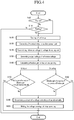
- the voltage detecting unit 116 At key-on and parking, the voltage detecting unit 116 generates an output voltage corresponding to the transmitted reference voltage Vref.
- the method involves determining abnormalities of the circuit of the voltage detecting unit 116, using an effective gain calculated by dividing the generated output voltage by a reference voltage Vref, is described in detail.
- the method can comprise an operation S100 as to whether a key-on signal is received from a vehicle.
- the MCU 20 determines whether a key-on signal is detected. If a key-on signal is received, the method proceeds to operation S120.
- the MCU 20 transmits the first control signal.
- the first control signal turns off all of the cell relays, for example, cell relays 111_1-111_40.
- the MCU 20 transmits a second control signal to the 3-contact relay 113.
- the 3-contact relay 113 connects the first contact S1, of the 3-contact_switch1 1131 with the first electrode of the capacitor C1.
- the 3-contact relay also connects the first contact S3, of the 3-contact_switch2 1132, with the second electrode of the capacitor C1.
- a reference voltage Vref is transmitted to the capacitor C1.
- the voltage detecting unit 116 generates an output voltage corresponding to the transmitted reference voltage Vref.
- the MCU 20 calculates an effective gain. The effective gain can be calculated by dividing the generated output voltage by the reference voltage Vref.
- the MCU 20 compares the effective gain from operation S160 with a previous effective gain of on just previous off.
- the previous effective gain can be the effective gain determined at the previous key-off.
- the effective gain determined in operation S160 can be referred to as an effective gain at key-on. If, during operation S170, the effective gain at key-on is determined to be the same as the previous effective gain, the MCU 20 determines that the circuit of the voltage detecting unit 116 is operating normally and the method ends. The method can then be repeated.
- the method proceeds to operation S190.
- the MCU 20 determines that the circuit of the voltage detecting unit 116 has an abnormality.
- the MCU transmits a first control signal to the cell relays 111_1 to 111_40 and thereby turns off the cell relays 111_1 to 111_40. If a key-on is not determined in operation S100, the MCU 20 makes a parking determination in operation S110. If parking is not detected, the MCU 20 does not determine an abnormality of the circuit of the voltage detecting unit 116, and the method ends.
- the method can proceed to operation S120.
- the MCU 20 transmits the first control signal and connects the cell relays 111_1-111_40, of the voltage sensing unit 110.
- the MCU 20 transmits the second control signal to the 3-contact relay 113.
- the 3-contact relay 113 connects the first contact S1, of the 3-contact_switch1 1131, with the first electrode of the capacitor C1 and connects the first contact S3, of the 3-contact_switch2 1132, with the second electrode of the capacitor C1.
- the MCU 20 transmits the reference voltage Vref to the capacitor C1.
- the 3-contact relay 113 transmits the reference voltage Vref to the capacitor C1.
- the voltage detecting unit 116 generates the output voltage corresponding to the transmitted reference voltage Vref.
- the MCU 20 divides the generated output voltage by the reference voltage Vref, and calculates an effective gain on parking.
- the MCU 20 compares the effective gain on parking to the previous effective gain.
- the previous effective gain can be, for example, the effective gain determined at key on.
- the effective gain determined in operation S160 can be referred to as an effective gain at parking. If the effective gain at parking is determined to be the same as the previous effective gain, the MCU determines that the circuit of the voltage detecting unit is operating normally, and the method ends. In some embodiments the method then starts again.
- the method proceeds to operation S190.
- the MCU 20 determines that the circuit of the voltage detecting unit has an abnormality.
- the MCU 20 makes the voltage detecting unit 116 stop operating entirely.
- a battery management system and a method thereof according to an exemplary embodiment of the present invention may determine an abnormality of the circuit of the voltage detecting unit using the reference voltage on key-on and parking.
- a battery management system and a method thereof according to an exemplary embodiment of the present invention may configure a circuit simply in comparison with the conventional voltage detecting circuit.
- the simple circuit determines an abnormality of the voltage detecting unit so that it may reduce cost and prevent a small current leakage.
Landscapes
- Engineering & Computer Science (AREA)
- Power Engineering (AREA)
- Life Sciences & Earth Sciences (AREA)
- Sustainable Development (AREA)
- Sustainable Energy (AREA)
- Transportation (AREA)
- Mechanical Engineering (AREA)
- Chemical & Material Sciences (AREA)
- Manufacturing & Machinery (AREA)
- Chemical Kinetics & Catalysis (AREA)
- Electrochemistry (AREA)
- General Chemical & Material Sciences (AREA)
- Electric Propulsion And Braking For Vehicles (AREA)
- Secondary Cells (AREA)
- Charge And Discharge Circuits For Batteries Or The Like (AREA)
- Tests Of Electric Status Of Batteries (AREA)
Claims (12)
- Fahrzeugbatterieverwaltungssystem für eine Mehrzahl von Zellen (2), umfassend:eine Mehrzahl von Zellenrelais (111_1 bis 111_40), wobei jedes Zellenrelais vorgesehen ist für das Koppeln an eine jeweilige Zelle der Mehrzahl von Zellen zum selektiven Bereitstellen einer Zellenspannung aus jeder der Zellen als eine erste Eingangsspannung;eine Hilfsstromversorgungseinheit (112) zum Bereitstellen einer zweiten Eingangsspannung, die eine Bezugsspannung ist;eine Spannungsdetektionseinheit (116), umfassend:ein 3-Kontaktrelais (113), das so angeordnet ist, dass es als Reaktion auf ein Steuersignal zwischen der ersten Eingangsspannung und der zweiten Eingangsspannung umschaltet, um eine erste Ausgangsspannung bereitzustellen, wobei das 3-Kontaktrelais so gesteuert wird, dass es auf die zweite Eingangsspannung umschaltet, wenn das Fahrzeug anfänglich eingeschaltet wird oder wenn das Fahrzeug parkt; undeinen Differentialverstärker (115, 115') zum Erzeugen einer zweiten Ausgangsspannung als Reaktion auf die erste Ausgangsspannung undeine Steuereinheit MCU (20) zum Bereitstellen des Steuersignals für das 3-Kontaktrelais (113) und zum Berechnen des Verhältnisses der zweiten Ausgangsspannung zu der zweiten Eingangsspannung, um eine wirksame Verstärkung der Spannungsdetektionseinheit (116) bereitzustellen, und zum Vergleichen einer bei dem anfänglichen Einschalten des Fahrzeugs berechneten wirksamen Verstärkung mit einer bei einem vorherigen Parken berechneten wirksamen Verstärkung, um zu bestimmen, ob eine Schaltung der Spannungsdetektionsmittel eine Abnormalität aufweist.
- System nach einem der vorangehenden Ansprüche, wobei das Spannungsdetektionsmittel ferner Mittel zum Speichern der ersten Ausgangsspannung (C1) umfasst.
- System nach Anspruch 2, wobei das Speichermittel einen Kondensator umfasst.
- System nach einem der vorangehenden Ansprüche, wobei der Differentialverstärker (115) die zweite Ausgangsspannung durch Verstärken der ersten Ausgangsspannung erzeugt.
- System nach einem der Ansprüche 1 bis 3, wobei das Mittel zum Erzeugen der zweiten Ausgangsspannung einen Spannungsfolger (115') zum Empfangen der ersten Ausgangsspannung und Übertragen der zweiten Ausgangsspannung, die die gleiche wie die erste Ausgangsspannung ist, umfasst.
- System nach Anspruch 1, wobei die MCU so angeordnet ist, dass sie eine beim Parken berechnete wirksame Verstärkung mit einer bei einem vorherigen anfänglichen Einschalten des Fahrzeugs berechneten vorherigen wirksamen Verstärkung vergleicht, um zu bestimmen, ob eine Schaltung der Spannungsdetektionsmittel eine Abnormalität aufweist.
- System nach einem der vorangehenden Ansprüche, ferner umfassend einen A/D-Wandler (117) zum Umwandeln der zweiten Ausgangsspannung vor der Übertragung an die MCU.
- System nach einem der vorangehenden Ansprüche, ferner umfassend ein Steuerrelais zum selektiven Anschließen von Speichermitteln (C1) zum Speichern der ersten Ausgangsspannung und der Mittel zum Erzeugen der zweiten Ausgangsspannung (115, 115').
- Batterieverwaltungsverfahren für ein Batterieverwaltungssystem in einem Fahrzeug nach einem der vorangehenden Ansprüche, umfassend:Koppeln an eine jeweilige Zelle der Mehrzahl von Zellen;Übertragen einer Zellenspannung aus der ausgewählten Zelle als die erste Eingangsspannung an das 3-Kontaktrelais;Übertragen der Bezugsspannung als die zweite Eingangsspannung an das 3-Kontaktrelais bei dem anfänglichen Einschalten des Fahrzeugs oder beim Parken;Umschalten, als Reaktion auf das Steuersignal, zwischen der ersten Eingangsspannung und der zweiten Eingangsspannung, um die erste Ausgangsspannung bereitzustellen;Erzeugen der zweiten Ausgangsspannung als Reaktion auf die erste Ausgangsspannung;Berechnen einer wirksamen Verstärkung gemäß einem Verhältnis der zweiten Ausgangsspannung zu der Bezugsspannung; undVergleichen der wirksamen Verstärkung mit einer bei einem vorherigen Einschalten des Fahrzeugs oder einem vorherigen Parken berechneten vorherigen wirksamen Verstärkung, um zu bestimmen, ob eine Schaltung der Spannungsdetektionsmittel eine Abnormalität aufweist.
- Verfahren nach Anspruch 9, wobei das Erzeugen der zweiten Ausgangsspannung das Verstärken der ersten Ausgangsspannung gemäß einer Verstärkung umfasst.
- Verfahren nach Anspruch 9, wobei das Vergleichen der wirksamen Verstärkung ferner umfasst: das Bestimmen, dass das System eine Abnormalität aufweist, wenn die bei dem anfänglichen Einschalten des Fahrzeugs berechnete wirksame Verstärkung nicht die gleiche ist wie die bei dem vorherigen Parken berechnete wirksame Verstärkung.
- Verfahren nach Anspruch 9, wobei das Vergleichen der wirksamen Verstärkung ferner umfasst: das Bestimmen, dass das System eine Abnormalität aufweist, wenn die beim Parken berechnete wirksame Verstärkung nicht die gleiche ist wie die bei dem vorherigen anfänglichen Einschalten des Fahrzeugs berechnete wirksame Verstärkung.
Applications Claiming Priority (1)
| Application Number | Priority Date | Filing Date | Title |
|---|---|---|---|
| KR1020060086149A KR100846710B1 (ko) | 2006-09-07 | 2006-09-07 | 배터리 관리 시스템 및 그의 구동 방법 |
Publications (3)
| Publication Number | Publication Date |
|---|---|
| EP1901412A2 EP1901412A2 (de) | 2008-03-19 |
| EP1901412A3 EP1901412A3 (de) | 2014-03-05 |
| EP1901412B1 true EP1901412B1 (de) | 2018-08-08 |
Family
ID=38853367
Family Applications (1)
| Application Number | Title | Priority Date | Filing Date |
|---|---|---|---|
| EP07115323.3A Ceased EP1901412B1 (de) | 2006-09-07 | 2007-08-30 | System und Verfahren zur Batterieverwaltung |
Country Status (5)
| Country | Link |
|---|---|
| US (1) | US7728599B2 (de) |
| EP (1) | EP1901412B1 (de) |
| JP (1) | JP4733079B2 (de) |
| KR (1) | KR100846710B1 (de) |
| CN (1) | CN101141076B (de) |
Families Citing this family (45)
| Publication number | Priority date | Publication date | Assignee | Title |
|---|---|---|---|---|
| US7994755B2 (en) * | 2008-01-30 | 2011-08-09 | Lg Chem, Ltd. | System, method, and article of manufacture for determining an estimated battery cell module state |
| KR20110021397A (ko) | 2009-08-26 | 2011-03-04 | 에스비리모티브 주식회사 | 배터리 관리 시스템 |
| US8493053B2 (en) * | 2009-12-18 | 2013-07-23 | GRID20/20, Inc. | System and device for measuring voltage in a conductor |
| KR101136151B1 (ko) * | 2010-01-27 | 2012-04-16 | 에스비리모티브 주식회사 | 이차 전지 |
| EP2551686B1 (de) * | 2010-03-26 | 2014-05-07 | Mitsubishi Electric Corporation | Vorrichtung zur kalkulation des ladezustandes |
| CN102243605B (zh) * | 2010-05-14 | 2014-04-30 | 鸿富锦精密工业(深圳)有限公司 | 检测装置及其检测方法 |
| US20130063154A1 (en) * | 2010-05-28 | 2013-03-14 | Sanyo Electric Co., Ltd. | Power supply apparatus |
| JP5450812B2 (ja) * | 2010-05-31 | 2014-03-26 | 三洋電機株式会社 | 電池システム、電動車両、移動体、電力貯蔵装置、電源装置及び電池電圧検出装置 |
| JP5606871B2 (ja) * | 2010-10-26 | 2014-10-15 | ラピスセミコンダクタ株式会社 | 半導体回路、半導体装置、配線の異常診断方法、及び異常診断プログラム |
| CN102623760A (zh) * | 2011-01-26 | 2012-08-01 | 上海樟村电子有限公司 | 一种电池管理系统 |
| WO2012132220A1 (ja) * | 2011-03-31 | 2012-10-04 | ルネサスエレクトロニクス株式会社 | 電圧監視モジュール及びこれを用いた電圧監視システム |
| US8449998B2 (en) | 2011-04-25 | 2013-05-28 | Lg Chem, Ltd. | Battery system and method for increasing an operational life of a battery cell |
| US9293936B2 (en) * | 2011-06-17 | 2016-03-22 | Yura Corporation Co., Ltd. | Power relay assembly driving apparatus and driving method thereof |
| CN102231553B (zh) * | 2011-07-06 | 2016-03-23 | 天津市松正电动汽车技术股份有限公司 | 带电源控制的电池管理系统 |
| US9048670B2 (en) | 2011-07-12 | 2015-06-02 | National Semiconductor Corporation | System and method for balancing electrical energy storage devices via differential power bus and capacitive load switched-mode power supply |
| US8970162B2 (en) | 2011-07-12 | 2015-03-03 | Texas Instruments Incorporated | System and method for balancing electrical energy storage devices via differential power bus and capacitive load switched-mode power supply |
| WO2013057820A1 (ja) * | 2011-10-20 | 2013-04-25 | 日立ビークルエナジー株式会社 | 電池システムの監視装置およびこれを備えた蓄電装置 |
| JP5468594B2 (ja) * | 2011-11-14 | 2014-04-09 | 本田技研工業株式会社 | 電動車両の電源装置 |
| US8775008B2 (en) * | 2011-12-14 | 2014-07-08 | GTR Development LLC | Electrical system health monitor (ESHM) system and method |
| US9107803B2 (en) * | 2012-02-05 | 2015-08-18 | Ricky Lee Vaught | Container with storage chambers |
| FR2993515B1 (fr) * | 2012-07-23 | 2015-12-25 | Renault Sas | Procede de fonctionnement d'un vehicule automobile comprenant un systeme d'alimentation electrique |
| DE102012213422A1 (de) * | 2012-07-31 | 2014-02-06 | Robert Bosch Gmbh | Batteriemanagementsystem, Kraftfahrzeug und Batteriesystem |
| KR101394751B1 (ko) * | 2012-12-28 | 2014-05-15 | 현대자동차주식회사 | Dc-dc 컨버터의 퓨즈 단선 검출 방법 |
| CN103171451B (zh) * | 2013-04-03 | 2015-03-04 | 山东大学 | 基于协处理器和固态继电器的电池管理系统 |
| CN103792492B (zh) * | 2014-01-22 | 2017-01-25 | 浙江精雷电器股份有限公司 | 一种蓄电池参数监测仪 |
| CN103792494B (zh) * | 2014-01-22 | 2017-01-25 | 浙江精雷电器股份有限公司 | 小型电动车辆动力管理装置 |
| DE102014206538A1 (de) * | 2014-04-04 | 2015-10-08 | Robert Bosch Gmbh | Verfahren und Vorrichtung zur Erhöhung der Sicherheit beim Gebrauch von Batteriesystemen |
| US10033213B2 (en) * | 2014-09-30 | 2018-07-24 | Johnson Controls Technology Company | Short circuit wake-up system and method for automotive battery while in key-off position |
| ITUB20152010A1 (it) * | 2015-07-09 | 2017-01-09 | Magneti Marelli Spa | Dispositivo elettronico di controllo di pacco batteria per veicolo e sistema impiegante tale dispositivo |
| US9931960B2 (en) * | 2015-09-11 | 2018-04-03 | Ford Global Technologies, Llc | Electric or hybrid vehicle battery pack voltage measurement functional assessment and redundancy |
| DE102015117744A1 (de) | 2015-10-19 | 2017-04-20 | Dr. Ing. H.C. F. Porsche Aktiengesellschaft | Batteriesystem |
| CN106992558A (zh) * | 2016-01-21 | 2017-07-28 | 华为技术有限公司 | 一种充放电控制装置 |
| KR102051177B1 (ko) | 2016-10-19 | 2019-12-17 | 주식회사 엘지화학 | 전압 분배를 이용한 스위치 진단 장치 및 방법 |
| CN106501734B (zh) * | 2016-12-29 | 2019-05-31 | 东莞钜威动力技术有限公司 | 电池管理系统的电压采集故障处理方法及装置 |
| US10322688B2 (en) | 2016-12-30 | 2019-06-18 | Textron Innovations Inc. | Controlling electrical access to a lithium battery on a utility vehicle |
| KR102173778B1 (ko) * | 2017-07-25 | 2020-11-03 | 주식회사 엘지화학 | 배터리 관리 유닛 및 이를 포함하는 배터리팩 |
| KR102173777B1 (ko) * | 2017-07-25 | 2020-11-03 | 주식회사 엘지화학 | 마스터 배터리 관리 유닛 및 이를 포함하는 배터리팩 |
| KR102478054B1 (ko) * | 2017-10-18 | 2022-12-16 | 현대자동차주식회사 | 차량용 배터리 시스템 |
| CN209479443U (zh) | 2018-12-29 | 2019-10-11 | 宁德时代新能源科技股份有限公司 | 一种电池加热系统 |
| JP7626700B2 (ja) * | 2019-07-25 | 2025-02-04 | ヌヴォトンテクノロジージャパン株式会社 | 電池管理回路、蓄電装置および電池管理方法 |
| KR20210111060A (ko) | 2020-03-02 | 2021-09-10 | 주식회사 럼플리어 | 폐배터리 재활용을 위한 배터리관리시스템 |
| CN114696571B (zh) * | 2020-12-31 | 2025-08-26 | 致茂电子(苏州)有限公司 | 电压控制方法 |
| TWI783340B (zh) * | 2020-12-31 | 2022-11-11 | 致茂電子股份有限公司 | 電壓控制方法 |
| US11791641B2 (en) * | 2021-11-17 | 2023-10-17 | GM Global Technology Operations LLC | High-voltage component protection during vehicle recharging |
| KR102621445B1 (ko) | 2023-01-02 | 2024-01-09 | 주식회사 케이에이치티 | 항공기용 배터리 관리 시스템 및 그 제어 방법 |
Citations (2)
| Publication number | Priority date | Publication date | Assignee | Title |
|---|---|---|---|---|
| US20020075004A1 (en) * | 2000-11-02 | 2002-06-20 | Hirofumi Yudahira | Battery voltage measurement device |
| US20040174170A1 (en) * | 2003-03-05 | 2004-09-09 | Tae Woo Kim | Method and apparatus for measuring voltage of battery module of electric vehicle |
Family Cites Families (17)
| Publication number | Priority date | Publication date | Assignee | Title |
|---|---|---|---|---|
| US4313080A (en) * | 1978-05-22 | 1982-01-26 | Battery Development Corporation | Method of charge control for vehicle hybrid drive batteries |
| US5530335A (en) * | 1993-05-11 | 1996-06-25 | Trw Inc. | Battery regulated bus spacecraft power control system |
| CN2278224Y (zh) * | 1996-05-20 | 1998-04-08 | 伍继先 | 蓄电池组自动监测仪 |
| US6486871B1 (en) * | 1996-08-30 | 2002-11-26 | Semtech Corporation | Pointing device with Z-axis functionality and reduced component count |
| DE19882652T1 (de) * | 1997-09-01 | 2000-09-07 | Batteryguard Ltd | Batterieladungsanzeiger |
| JP2001086656A (ja) * | 1999-07-09 | 2001-03-30 | Fujitsu Ltd | バッテリ監視装置 |
| JP2001178008A (ja) * | 1999-12-20 | 2001-06-29 | Nec Corp | セルバランス調整回路、セル電圧異常検出回路、セルバランス調整方法およびセル電圧異常検出方法 |
| JP4047558B2 (ja) * | 2001-05-29 | 2008-02-13 | 松下電器産業株式会社 | 電池電圧検出装置 |
| JP4118035B2 (ja) * | 2001-08-03 | 2008-07-16 | トヨタ自動車株式会社 | 電池制御装置 |
| US7301308B2 (en) * | 2001-11-02 | 2007-11-27 | Aker Wade Power Technologies, Llc | Fast charger for high capacity batteries |
| US6983212B2 (en) * | 2001-11-27 | 2006-01-03 | American Power Conversion Corporation | Battery management system and method |
| JP2003240806A (ja) * | 2002-02-15 | 2003-08-27 | Yazaki Corp | 組電池のセル電圧測定装置及びその方法 |
| JP4158458B2 (ja) * | 2002-08-28 | 2008-10-01 | ソニー株式会社 | 情報処理装置、その情報処理方法 |
| JP4254209B2 (ja) * | 2002-11-22 | 2009-04-15 | 新神戸電機株式会社 | 電池電圧検出線の検査方法、検査回路及び電池モジュール |
| JP4447526B2 (ja) * | 2004-07-20 | 2010-04-07 | パナソニックEvエナジー株式会社 | 組電池のための異常電圧検出装置 |
| KR100697528B1 (ko) * | 2004-12-31 | 2007-03-20 | 주식회사 케피코 | 하이브리드 자동차용 배터리 전압 검출부 보호회로 |
| JP3804682B2 (ja) * | 2005-03-18 | 2006-08-02 | 日産自動車株式会社 | 車両用組電池の電圧検出装置 |
-
2006
- 2006-09-07 KR KR1020060086149A patent/KR100846710B1/ko not_active Expired - Fee Related
-
2007
- 2007-07-13 JP JP2007184747A patent/JP4733079B2/ja not_active Expired - Fee Related
- 2007-08-28 CN CN200710147761XA patent/CN101141076B/zh not_active Expired - Fee Related
- 2007-08-30 EP EP07115323.3A patent/EP1901412B1/de not_active Ceased
- 2007-08-31 US US11/848,680 patent/US7728599B2/en not_active Expired - Fee Related
Patent Citations (2)
| Publication number | Priority date | Publication date | Assignee | Title |
|---|---|---|---|---|
| US20020075004A1 (en) * | 2000-11-02 | 2002-06-20 | Hirofumi Yudahira | Battery voltage measurement device |
| US20040174170A1 (en) * | 2003-03-05 | 2004-09-09 | Tae Woo Kim | Method and apparatus for measuring voltage of battery module of electric vehicle |
Also Published As
| Publication number | Publication date |
|---|---|
| KR100846710B1 (ko) | 2008-07-16 |
| EP1901412A3 (de) | 2014-03-05 |
| EP1901412A2 (de) | 2008-03-19 |
| US20080061764A1 (en) | 2008-03-13 |
| CN101141076A (zh) | 2008-03-12 |
| CN101141076B (zh) | 2012-06-13 |
| KR20080022676A (ko) | 2008-03-12 |
| JP2008066288A (ja) | 2008-03-21 |
| US7728599B2 (en) | 2010-06-01 |
| JP4733079B2 (ja) | 2011-07-27 |
Similar Documents
| Publication | Publication Date | Title |
|---|---|---|
| EP1901412B1 (de) | System und Verfahren zur Batterieverwaltung | |
| CN101188316B (zh) | 感测和控制装置及利用该装置的电池管理系统的驱动方法 | |
| EP1897772B1 (de) | Batterieverwaltungssystem und Antriebsverfahren | |
| EP1919059B1 (de) | System und Antriebsverfahren zur Batterieverwaltung | |
| US8405352B2 (en) | Battery management system and battery management method | |
| US7652449B2 (en) | Battery management system and driving method thereof | |
| CN1988242B (zh) | 补偿电池充电状态的方法、电池管理系统和混合动力车辆 | |
| JP4987581B2 (ja) | 電池制御装置 | |
| KR100814883B1 (ko) | 배터리 관리 시스템 및 그의 구동 방법 | |
| KR101552903B1 (ko) | 배터리 관리 시스템 및 방법 | |
| EP1914559A2 (de) | Batterieverwaltungssystem und Verfahren zu dessen Ansteuerung | |
| KR20080028161A (ko) | 배터리 관리 시스템 및 그 구동방법 | |
| KR100846712B1 (ko) | 배터리 관리 시스템 및 그의 구동 방법 | |
| JP2022545352A (ja) | 低電圧セル検出方法およびその方法を提供するバッテリー管理システム | |
| KR102884456B1 (ko) | 전원 고장 판별 장치 및 방법 |
Legal Events
| Date | Code | Title | Description |
|---|---|---|---|
| PUAI | Public reference made under article 153(3) epc to a published international application that has entered the european phase |
Free format text: ORIGINAL CODE: 0009012 |
|
| 17P | Request for examination filed |
Effective date: 20070830 |
|
| AK | Designated contracting states |
Kind code of ref document: A2 Designated state(s): AT BE BG CH CY CZ DE DK EE ES FI FR GB GR HU IE IS IT LI LT LU LV MC MT NL PL PT RO SE SI SK TR |
|
| AX | Request for extension of the european patent |
Extension state: AL BA HR MK YU |
|
| RAP1 | Party data changed (applicant data changed or rights of an application transferred) |
Owner name: SAMSUNG SDI CO., LTD. |
|
| PUAL | Search report despatched |
Free format text: ORIGINAL CODE: 0009013 |
|
| AK | Designated contracting states |
Kind code of ref document: A3 Designated state(s): AT BE BG CH CY CZ DE DK EE ES FI FR GB GR HU IE IS IT LI LT LU LV MC MT NL PL PT RO SE SI SK TR |
|
| AX | Request for extension of the european patent |
Extension state: AL BA HR MK RS |
|
| RIC1 | Information provided on ipc code assigned before grant |
Ipc: B60L 3/00 20060101ALI20140128BHEP Ipc: B60L 11/18 20060101ALI20140128BHEP Ipc: B60L 3/12 20060101ALI20140128BHEP Ipc: H02J 7/00 20060101AFI20140128BHEP Ipc: H02J 7/14 20060101ALI20140128BHEP |
|
| AKX | Designation fees paid |
Designated state(s): DE FR GB HU |
|
| 17Q | First examination report despatched |
Effective date: 20160808 |
|
| STAA | Information on the status of an ep patent application or granted ep patent |
Free format text: STATUS: EXAMINATION IS IN PROGRESS |
|
| GRAP | Despatch of communication of intention to grant a patent |
Free format text: ORIGINAL CODE: EPIDOSNIGR1 |
|
| STAA | Information on the status of an ep patent application or granted ep patent |
Free format text: STATUS: GRANT OF PATENT IS INTENDED |
|
| INTG | Intention to grant announced |
Effective date: 20180425 |
|
| RIN1 | Information on inventor provided before grant (corrected) |
Inventor name: SEO, SE-WOOK Inventor name: LEE, YOUNG-JO Inventor name: PARK, HO-YOUNG Inventor name: TAE, YONG-JUN Inventor name: YUN, HAN-SEOK Inventor name: CHOI, SOO-SEOK Inventor name: LIM, GYE-JONG Inventor name: KIM, BEOM-GYU |
|
| GRAS | Grant fee paid |
Free format text: ORIGINAL CODE: EPIDOSNIGR3 |
|
| GRAA | (expected) grant |
Free format text: ORIGINAL CODE: 0009210 |
|
| STAA | Information on the status of an ep patent application or granted ep patent |
Free format text: STATUS: THE PATENT HAS BEEN GRANTED |
|
| AK | Designated contracting states |
Kind code of ref document: B1 Designated state(s): DE FR GB HU |
|
| RAP1 | Party data changed (applicant data changed or rights of an application transferred) |
Owner name: SAMSUNG SDI CO., LTD. |
|
| REG | Reference to a national code |
Ref country code: GB Ref legal event code: FG4D |
|
| REG | Reference to a national code |
Ref country code: FR Ref legal event code: PLFP Year of fee payment: 12 |
|
| REG | Reference to a national code |
Ref country code: DE Ref legal event code: R096 Ref document number: 602007055631 Country of ref document: DE |
|
| REG | Reference to a national code |
Ref country code: DE Ref legal event code: R097 Ref document number: 602007055631 Country of ref document: DE |
|
| PLBE | No opposition filed within time limit |
Free format text: ORIGINAL CODE: 0009261 |
|
| STAA | Information on the status of an ep patent application or granted ep patent |
Free format text: STATUS: NO OPPOSITION FILED WITHIN TIME LIMIT |
|
| 26N | No opposition filed |
Effective date: 20190509 |
|
| PG25 | Lapsed in a contracting state [announced via postgrant information from national office to epo] |
Ref country code: HU Free format text: LAPSE BECAUSE OF FAILURE TO SUBMIT A TRANSLATION OF THE DESCRIPTION OR TO PAY THE FEE WITHIN THE PRESCRIBED TIME-LIMIT; INVALID AB INITIO Effective date: 20070830 |
|
| PGFP | Annual fee paid to national office [announced via postgrant information from national office to epo] |
Ref country code: DE Payment date: 20200819 Year of fee payment: 14 Ref country code: GB Payment date: 20200819 Year of fee payment: 14 Ref country code: FR Payment date: 20200812 Year of fee payment: 14 |
|
| REG | Reference to a national code |
Ref country code: DE Ref legal event code: R119 Ref document number: 602007055631 Country of ref document: DE |
|
| GBPC | Gb: european patent ceased through non-payment of renewal fee |
Effective date: 20210830 |
|
| PG25 | Lapsed in a contracting state [announced via postgrant information from national office to epo] |
Ref country code: GB Free format text: LAPSE BECAUSE OF NON-PAYMENT OF DUE FEES Effective date: 20210830 Ref country code: FR Free format text: LAPSE BECAUSE OF NON-PAYMENT OF DUE FEES Effective date: 20210831 Ref country code: DE Free format text: LAPSE BECAUSE OF NON-PAYMENT OF DUE FEES Effective date: 20220301 |