EP1901420A2 - Vorrichtung zur Steuerung eines Elektromotors und einer Mensch-Maschine-Schnittstelle ohne Nullleiteranschluss - Google Patents
Vorrichtung zur Steuerung eines Elektromotors und einer Mensch-Maschine-Schnittstelle ohne Nullleiteranschluss Download PDFInfo
- Publication number
- EP1901420A2 EP1901420A2 EP07360041A EP07360041A EP1901420A2 EP 1901420 A2 EP1901420 A2 EP 1901420A2 EP 07360041 A EP07360041 A EP 07360041A EP 07360041 A EP07360041 A EP 07360041A EP 1901420 A2 EP1901420 A2 EP 1901420A2
- Authority
- EP
- European Patent Office
- Prior art keywords
- stage
- power supply
- switch
- control
- switching
- Prior art date
- Legal status (The legal status is an assumption and is not a legal conclusion. Google has not performed a legal analysis and makes no representation as to the accuracy of the status listed.)
- Granted
Links
Images

Classifications
-
- H—ELECTRICITY
- H02—GENERATION; CONVERSION OR DISTRIBUTION OF ELECTRIC POWER
- H02P—CONTROL OR REGULATION OF ELECTRIC MOTORS, ELECTRIC GENERATORS OR DYNAMO-ELECTRIC CONVERTERS; CONTROLLING TRANSFORMERS, REACTORS OR CHOKE COILS
- H02P25/00—Arrangements or methods for the control of AC motors characterised by the kind of AC motor or by structural details
- H02P25/02—Arrangements or methods for the control of AC motors characterised by the kind of AC motor or by structural details characterised by the kind of motor
- H02P25/04—Single phase motors, e.g. capacitor motors
-
- H—ELECTRICITY
- H02—GENERATION; CONVERSION OR DISTRIBUTION OF ELECTRIC POWER
- H02P—CONTROL OR REGULATION OF ELECTRIC MOTORS, ELECTRIC GENERATORS OR DYNAMO-ELECTRIC CONVERTERS; CONTROLLING TRANSFORMERS, REACTORS OR CHOKE COILS
- H02P1/00—Arrangements for starting electric motors or dynamo-electric converters
- H02P1/16—Arrangements for starting electric motors or dynamo-electric converters for starting dynamo-electric motors or dynamo-electric converters
- H02P1/26—Arrangements for starting electric motors or dynamo-electric converters for starting dynamo-electric motors or dynamo-electric converters for starting an individual polyphase induction motor
-
- H—ELECTRICITY
- H02—GENERATION; CONVERSION OR DISTRIBUTION OF ELECTRIC POWER
- H02P—CONTROL OR REGULATION OF ELECTRIC MOTORS, ELECTRIC GENERATORS OR DYNAMO-ELECTRIC CONVERTERS; CONTROLLING TRANSFORMERS, REACTORS OR CHOKE COILS
- H02P1/00—Arrangements for starting electric motors or dynamo-electric converters
- H02P1/16—Arrangements for starting electric motors or dynamo-electric converters for starting dynamo-electric motors or dynamo-electric converters
- H02P1/42—Arrangements for starting electric motors or dynamo-electric converters for starting dynamo-electric motors or dynamo-electric converters for starting an individual single-phase induction motor
-
- E—FIXED CONSTRUCTIONS
- E06—DOORS, WINDOWS, SHUTTERS, OR ROLLER BLINDS IN GENERAL; LADDERS
- E06B—FIXED OR MOVABLE CLOSURES FOR OPENINGS IN BUILDINGS, VEHICLES, FENCES OR LIKE ENCLOSURES IN GENERAL, e.g. DOORS, WINDOWS, BLINDS, GATES
- E06B9/00—Screening or protective devices for wall or similar openings, with or without operating or securing mechanisms; Closures of similar construction
- E06B9/56—Operating, guiding or securing devices or arrangements for roll-type closures; Spring drums; Tape drums; Counterweighting arrangements therefor
- E06B9/68—Operating devices or mechanisms, e.g. with electric drive
Definitions
- the invention relates to a device for controlling, on the one hand, a motor with two coils intended for opening and closing, assisted by electromechanical limit switches, of an opening, and on the other hand the supplying a man-machine interface for example of the remote control type of said opening, without connection to the neutral.
- the invention also relates to a method of supplying such a device to power up.
- the openings may be roller shutters, and the power supply then relates more particularly to a transceiver exchanging information with the remote control.
- the opening may be a gate, an awning or a sunshade and the man-machine interface may for example consist of a screen, without these examples being limiting.
- the power supply of the human-machine interface in this case for example the transceiver of the rolling shutter control head, only concerns a few tens of mA, and therefore requires only a fraction very reduced each half period of the sector.
- the main power of the transceiver connected in parallel with said switch, is actually powered through the motor.
- the neutral is not directly connected to this power supply, and is only available through the engine.
- the switching stage comprises a relay controllable by the control unit and driving a mechanical contact connectable alternately to the two conductors connected via two electromechanical limit switches to the motor.
- This contact relay allows switching on the circuit mounted up or down the shutter. The switching of the contact is carried out automatically on arrival at the end of a race. In certain cases, this switchover requires control by the control unit. Indeed, the main power being indifferently by the circuit up or down, and the position of the limit switches being unknown when powering the system, this power supply is not necessarily energized at startup: it is the problem to which the process of the invention responds, as will be described in more detail below.
- control unit when powering up the system, it is always necessary to detect the existence of voltage at the terminals of the main power supply, the control unit then loading, if necessary, to send a signal. switch signal of the contact so that the main power is actually turned on.
- the auxiliary power supply is put into operation.
- This includes a tank capacity loaded by the two conductors connected to the motor windings and providing temporary power to the control unit. This capacity is always on mains voltage while auxiliary power is on.
- the latter is of linear type and drifts only a small current, of the order of 20 mA maximum for a period of time that does not exceed a few milliseconds, when powering up. It is then automatically put into standby, as soon as the main power supply takes over, and it does not intervene before a next power up.
- the tank capacity is connected to a load resistor connected to a power transistor connected to the conductors connected to the motor windings.
- This transistor acts as a switch for activating / deactivating the auxiliary power supply.
- the main power can then automatically take over when energized, its output is connected to the base of a bipolar transistor connected in parallel to said Zener diode.
- a signal arrives from the main power supply, making the bipolar transistor passing and shunting the Zener diode, the MOS transistor is blocked and the auxiliary power is no longer activated.
- the tank capacity is placed at the output of an OR function whose inputs are respectively connected to the main power supply and to the load resistance of the power transistor. It is thus constantly maintained charged by the main power supply after having been through the auxiliary power supply.
- this auxiliary power supply is absolutely essential, in the context of the invention, since it makes it possible, if necessary, to perform the initial switching operation of the relay so that the main power supply can itself be powered up and ensure the normal operation of the system.
- the detection stage of the zero crossing of the mains voltage is for example constituted by an open-loop comparator connected in parallel with the control switch stage of the motor, the output of which is connected to the control unit.
- This comparator delivers a signal whose edges indicate the zero crossing of the mains voltage and therefore allow the synchronization of the control of the switch stage.
- the input of the main power supply is connected to a voltage presence detection stage at its terminals, the output of which is also connected to the power supply. control unit.
- this stage consists of a comparator whose inputs are respectively connected to the input of the main power supply connected to the switching stage and to a threshold voltage reference.
- said detection stage may comprise two NPN transistors, the base of the input transistor being connected via a resistance bridge to the input of the main power supply and the polarized collector of the output transistor being connected. to the control unit.
- the base of the output transistor is in fact connected to the collector of the input transistor and to a bias resistor that turns it on when the input transistor is off, and off when the input transistor is saturated.
- the signal at the output of this stage is in the high state when the input voltage level makes the input transistor passing, and in the low state in the opposite hypothesis.
- the signal output from this stage is also used for the detection of voltage interruptions, whether they are temporary (micro cuts) or of greater importance.
- the switch stage is conventionally constituted by two MOS or IGBT power transistors operating alternately in the event of reception of a control signal coming from the control unit.
- the blocking / unblocking instruction of these transistors comes from the control unit.
- said predetermined duration is between 700 and 900 ms. Furthermore, preferably, the loop test is performed three times consecutively.
- the switch stage (1) comprises two MOS transistors for the circulation of the alternating current of the network to the conductors (M, D) supplying the two windings of the motor and respectively allowing the control of the raising and lowering of the shutter in the event of such an application of the invention.
- the switching stage (5) comprises a relay (7) switching the mechanical contact (8) between two positions respectively allowing the closure of the rise circuit (M) or descent (D) of the shutter.
- the detection stage (3) of the zero crossing allows the development of a synchronization signal of the control of the switch (to allow, under good conditions, the realization of a phase division of the conduction type to the angle during engine control). It consists of a conventional comparator whose inputs are connected in parallel to the switch stage (1).
- an overcurrent detection device (9) for example using a shunt resistor whose voltage at the terminals is proportional to the current flowing through the motor, makes it possible to protect said stage (1) against short circuits.
- the control of the MOS transistors of the power stage (1) is operated by the control unit (2) via the connection (C).
- the main power supply (4) of the switching type for example consists of a switching DC / DC converter type BUCK. It uses a part of the mains voltage (a fraction of each half period) to supply the control unit (2), and the human-machine interface that this unit (2) manages secondarily.
- This main power supply (4) is fed through the motor (it "sees” the neutral through the motor), either continuously when the motor is not running, or discontinuously, for a fraction of each half period of the sector, when the engine is controlled.
- auxiliary power supply (6) is provided to temporarily provide supplying the control unit (2) until the main power supply (4) is energized.
- the signal (PFO) at the address of the control unit (2) indicates the absence of voltage across the main power supply (4).
- the auxiliary power supply (6) with its tank capacity (10) ensure the initial tensioning of the system.
- the control unit then sends, via the connections C M / C D , information to the address of the switching stage (5), forcing the contact (8) to change position, and thus allowing ensure the supply by the stage (4).
- the reservoir capacity (10) is only filled via the stage (4) when the MOS transistor (13) is on, that is to say when its gate is biased by the Zener diode (15).
- the load of the capacitor is through a resistor (14) that avoids the current peaks, for a charging time of about a half second.
- OR function (11) makes it possible to fill the tank capacity (10) in all operating cases, whether the auxiliary power supply (6) or the main power supply (4) are energized. .
- Another OR function (17) continuously supplies power to the control unit (2), regardless of the activated power stage.
- the microcontroller (2) consumes a low current, of the order of 2 to 3 mA, while the human-machine interface (transceiver) consumes a larger current of the order of 20 mA.
- the auxiliary power supply when the auxiliary power supply is activated, only the microcontroller (2) is therefore powered, the interface being kept dormant.
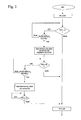
- the RF human-machine interface (whatever it may be) being deactivated, three tests of the signal state (PFO) at the output of the stage (12) are cascaded. detection of the presence of voltage (with reference to a threshold voltage (REF)) at the terminals of the main power supply (4), each time with a delay of the order of 800 ms.
- PFO signal state
- REF threshold voltage
- the microcontroller (2) In the first step, if the microcontroller (2) does not detect that the signal (PFO) is high, it goes on to the subsequent step after switching the relay (7) by state change.
Landscapes
- Engineering & Computer Science (AREA)
- Power Engineering (AREA)
- Operating, Guiding And Securing Of Roll- Type Closing Members (AREA)
- Control Of Electric Motors In General (AREA)
Applications Claiming Priority (1)
| Application Number | Priority Date | Filing Date | Title |
|---|---|---|---|
| FR0608146A FR2906092B1 (fr) | 2006-09-18 | 2006-09-18 | Dispositif de commande d'un moteur electrique et d'une interface homme-machine sans raccordement au neutre |
Publications (3)
| Publication Number | Publication Date |
|---|---|
| EP1901420A2 true EP1901420A2 (de) | 2008-03-19 |
| EP1901420A3 EP1901420A3 (de) | 2015-09-09 |
| EP1901420B1 EP1901420B1 (de) | 2018-11-14 |
Family
ID=37907684
Family Applications (1)
| Application Number | Title | Priority Date | Filing Date |
|---|---|---|---|
| EP07360041.3A Active EP1901420B1 (de) | 2006-09-18 | 2007-09-18 | Vorrichtung zur steuerung eines elektromotors und einer mensch-maschine-schnittstelle ohne nullleiteranschluss |
Country Status (2)
| Country | Link |
|---|---|
| EP (1) | EP1901420B1 (de) |
| FR (1) | FR2906092B1 (de) |
Cited By (1)
| Publication number | Priority date | Publication date | Assignee | Title |
|---|---|---|---|---|
| EP2528224A1 (de) * | 2011-05-24 | 2012-11-28 | Hager Controls | Steuerungsvorrichtung eines Motors für Rolläden, der mit oder ohne einen Nullleiter für den Stromanschluss ausgestattet ist |
Family Cites Families (3)
| Publication number | Priority date | Publication date | Assignee | Title |
|---|---|---|---|---|
| IT1254734B (it) * | 1992-03-24 | 1995-10-10 | Faac Spa | Metodo e dispositivo per il controllo della velocita' di motori asincroni |
| WO1997020381A1 (en) * | 1995-11-30 | 1997-06-05 | William Harry Kemp | Current modulation motor controller |
| FR2879047B1 (fr) * | 2004-12-07 | 2007-09-14 | Somfy Sas | Procede d'alimentation d'un moteur de manoeuvre d'un volet roulant et dispositif de volet roulant motorise |
-
2006
- 2006-09-18 FR FR0608146A patent/FR2906092B1/fr not_active Expired - Fee Related
-
2007
- 2007-09-18 EP EP07360041.3A patent/EP1901420B1/de active Active
Cited By (1)
| Publication number | Priority date | Publication date | Assignee | Title |
|---|---|---|---|---|
| EP2528224A1 (de) * | 2011-05-24 | 2012-11-28 | Hager Controls | Steuerungsvorrichtung eines Motors für Rolläden, der mit oder ohne einen Nullleiter für den Stromanschluss ausgestattet ist |
Also Published As
| Publication number | Publication date |
|---|---|
| FR2906092A1 (fr) | 2008-03-21 |
| EP1901420A3 (de) | 2015-09-09 |
| EP1901420B1 (de) | 2018-11-14 |
| FR2906092B1 (fr) | 2008-12-05 |
Similar Documents
| Publication | Publication Date | Title |
|---|---|---|
| CA1145815A (fr) | Dispositif de commutation automatique de deux batteries chargees en parallele et dechargees en serie | |
| FR2802360A1 (fr) | Procede et dispositif d'alimentation electrique d'une charge par un variateur a au moins un interrupteur commande | |
| CA1253578A (fr) | Systeme de soudage ou de coupage plasma muni d'une temporisation | |
| EP0766905B1 (de) | Anordnung zur fernsteuerung und fernüberwachung einer entladungslampe | |
| EP1901420B1 (de) | Vorrichtung zur steuerung eines elektromotors und einer mensch-maschine-schnittstelle ohne nullleiteranschluss | |
| EP3694068B1 (de) | Statisches schaltsystem und system zur begrenzung eines gleichstroms | |
| EP1271738A1 (de) | Elektronische Auslösevorrichtung mit einem Kondensator für die Stromversorgung einer Auslösespule | |
| FR2957205A1 (fr) | Dispositif et procede d'alimentation sans interruption en courant alternatif d'une installation | |
| EP2133977B1 (de) | Stromversorgungskreis einer Steuereinheit einer Heimanlage | |
| EP3323668B1 (de) | System und verfahren zur steuerung der unterbrechungsfreien stromversorgung im haushalt, die mit einem elektro- oder hybridfahrzeug verbunden ist | |
| EP0129454B1 (de) | Messverfahren um die Verfügbarkeit einer getakteten elektrischen Stromversorgung festzustellen und Vorrichtung zu seiner Durchführung | |
| JP2009027844A (ja) | 瞬低補償装置 | |
| WO2009013669A2 (fr) | Dispositif d'alimentation d'un actionneur domotique et procède de fonctionnement d'un tel dispositif | |
| BE898689A (fr) | Procede et appareil de blocage automatique d'un interrupteur de deconnexion de charge a proximite d'un defaut localise | |
| EP1741013B1 (de) | Verfahren zur schätzung einer dauer, während der ein rolladenstellglied ausgeschaltet ist | |
| FR2685830A1 (fr) | Installation d'alimentation comportant aux moins deux charges et leurs alimentations sans coupure respectives et procede de remplacement d'une alimentation par l'autre. | |
| FR2622750A1 (fr) | Systeme de controle du fonctionnement d'un groupe electrogene | |
| EP0864744A1 (de) | Verbesserung an Vorrichtungen zum Steuern eines Anlasschützes für einen Kraftfahrzeug | |
| FR2459542A1 (fr) | Dispositif de commutation de circuits a courant continu permettant notamment de supprimer la formation d'arcs et de reduire les ecarts de tension dus aux commutations | |
| EP2663166B1 (de) | Drahtlose Schaltung eines Erregungsschaltkreises eines zentralen Geräts vom Typ Zeitschalter, Fernschalter oder Regler | |
| EP2528224B1 (de) | Steuerungsvorrichtung eines Motors für Rolläden, der mit oder ohne einen Nullleiter für den Stromanschluss ausgestattet ist | |
| FR2540305A1 (en) | Remote control device for at least one security unit | |
| CH468736A (fr) | Bloc d'éclairage de sécurité | |
| WO2006018700A1 (fr) | Procede et dispositif d'alimentation d'un moteur electrique a courant continu | |
| FR2471067A2 (fr) | Dispositif de commutation automatique de deux batteries chargees en parallele et dechargees en serie |
Legal Events
| Date | Code | Title | Description |
|---|---|---|---|
| PUAI | Public reference made under article 153(3) epc to a published international application that has entered the european phase |
Free format text: ORIGINAL CODE: 0009012 |
|
| AK | Designated contracting states |
Kind code of ref document: A2 Designated state(s): AT BE BG CH CY CZ DE DK EE ES FI FR GB GR HU IE IS IT LI LT LU LV MC MT NL PL PT RO SE SI SK TR |
|
| AX | Request for extension of the european patent |
Extension state: AL BA HR MK YU |
|
| 17P | Request for examination filed |
Effective date: 20080917 |
|
| PUAL | Search report despatched |
Free format text: ORIGINAL CODE: 0009013 |
|
| AK | Designated contracting states |
Kind code of ref document: A3 Designated state(s): AT BE BG CH CY CZ DE DK EE ES FI FR GB GR HU IE IS IT LI LT LU LV MC MT NL PL PT RO SE SI SK TR |
|
| AX | Request for extension of the european patent |
Extension state: AL BA HR MK RS |
|
| RIC1 | Information provided on ipc code assigned before grant |
Ipc: H02P 1/26 20060101AFI20150803BHEP Ipc: E05F 15/10 00000000ALI20150803BHEP Ipc: H02P 25/04 20060101ALI20150803BHEP Ipc: E06B 9/68 20060101ALI20150803BHEP Ipc: H02P 1/42 20060101ALI20150803BHEP |
|
| AKX | Designation fees paid |
Designated state(s): CH DE FR LI |
|
| AXX | Extension fees paid |
Extension state: RS Extension state: AL Extension state: HR Extension state: MK Extension state: BA |
|
| GRAP | Despatch of communication of intention to grant a patent |
Free format text: ORIGINAL CODE: EPIDOSNIGR1 |
|
| RIC1 | Information provided on ipc code assigned before grant |
Ipc: H02P 1/42 20060101ALI20180517BHEP Ipc: H02P 1/26 20060101AFI20180517BHEP Ipc: E06B 9/68 20060101ALI20180517BHEP Ipc: H02P 25/04 20060101ALI20180517BHEP |
|
| INTG | Intention to grant announced |
Effective date: 20180613 |
|
| GRAS | Grant fee paid |
Free format text: ORIGINAL CODE: EPIDOSNIGR3 |
|
| GRAA | (expected) grant |
Free format text: ORIGINAL CODE: 0009210 |
|
| AK | Designated contracting states |
Kind code of ref document: B1 Designated state(s): CH DE FR LI |
|
| REG | Reference to a national code |
Ref country code: CH Ref legal event code: EP |
|
| REG | Reference to a national code |
Ref country code: DE Ref legal event code: R096 Ref document number: 602007056797 Country of ref document: DE |
|
| REG | Reference to a national code |
Ref country code: CH Ref legal event code: NV Representative=s name: RENTSCH PARTNER AG, CH |
|
| REG | Reference to a national code |
Ref country code: DE Ref legal event code: R097 Ref document number: 602007056797 Country of ref document: DE |
|
| PLBE | No opposition filed within time limit |
Free format text: ORIGINAL CODE: 0009261 |
|
| STAA | Information on the status of an ep patent application or granted ep patent |
Free format text: STATUS: NO OPPOSITION FILED WITHIN TIME LIMIT |
|
| 26N | No opposition filed |
Effective date: 20190815 |
|
| P01 | Opt-out of the competence of the unified patent court (upc) registered |
Effective date: 20230606 |
|
| REG | Reference to a national code |
Ref country code: CH Ref legal event code: U11 Free format text: ST27 STATUS EVENT CODE: U-0-0-U10-U11 (AS PROVIDED BY THE NATIONAL OFFICE) Effective date: 20251001 |
|
| PGFP | Annual fee paid to national office [announced via postgrant information from national office to epo] |
Ref country code: DE Payment date: 20250929 Year of fee payment: 19 |
|
| PGFP | Annual fee paid to national office [announced via postgrant information from national office to epo] |
Ref country code: FR Payment date: 20250925 Year of fee payment: 19 |
|
| PGFP | Annual fee paid to national office [announced via postgrant information from national office to epo] |
Ref country code: CH Payment date: 20251001 Year of fee payment: 19 |