EP1901538A1 - Séparateur de signal - Google Patents
Séparateur de signal Download PDFInfo
- Publication number
- EP1901538A1 EP1901538A1 EP06019188A EP06019188A EP1901538A1 EP 1901538 A1 EP1901538 A1 EP 1901538A1 EP 06019188 A EP06019188 A EP 06019188A EP 06019188 A EP06019188 A EP 06019188A EP 1901538 A1 EP1901538 A1 EP 1901538A1
- Authority
- EP
- European Patent Office
- Prior art keywords
- connecting port
- low
- signal
- pass filter
- terminal
- Prior art date
- Legal status (The legal status is an assumption and is not a legal conclusion. Google has not performed a legal analysis and makes no representation as to the accuracy of the status listed.)
- Withdrawn
Links
- 230000008878 coupling Effects 0.000 claims abstract description 21
- 238000010168 coupling process Methods 0.000 claims abstract description 21
- 238000005859 coupling reaction Methods 0.000 claims abstract description 21
- 238000004804 winding Methods 0.000 claims abstract description 10
- 239000003990 capacitor Substances 0.000 claims abstract description 5
- 238000010586 diagram Methods 0.000 description 3
Images
Classifications
-
- H—ELECTRICITY
- H04—ELECTRIC COMMUNICATION TECHNIQUE
- H04M—TELEPHONIC COMMUNICATION
- H04M11/00—Telephonic communication systems specially adapted for combination with other electrical systems
- H04M11/06—Simultaneous speech and data transmission, e.g. telegraphic transmission over the same conductors
- H04M11/062—Simultaneous speech and data transmission, e.g. telegraphic transmission over the same conductors using different frequency bands for speech and other data
Definitions
- the invention relates to a signal splitter, more particularly to a signal splitter capable ot reducing cross-talk phenomenon.
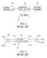
- Figures 1 and 2 illustrate a conventional signal splitter 81 that can be coupled among an incoming telephone line 82, a telephony instrument 83 and a digital subscriber line (DSL) modem 84, and that includes a first connecting port 813, a second connecting port 812 and a low-pass filter circuit 811.
- the first connecting port 813 is to be coupled to the incoming telephone line 82, and has first and second terminals 8131, 8132.
- the second connecting port 812 is to be coupled to the telephony instrument 83, and has first and second terminals 8121, 8122.
- the low-pass filter circuit 811 has first and second input ends 8111, 8112 connected electrically and respectively to the first and second terminals 8131, 8132 of the first connecting port 813, and first and second output ends 8113, 8114 connected electrically and respectively to the first and second terminals 8121, 8122 of the second connecting port 812.
- the low-pass filter circuit 811 is capable of permitting a low-frequency component of an incoming signal in the incoming telephone line 82 to pass therethrough to the second connecting port 812 in a known manner.
- the object of the present invention is to provide a signal splitter that can overcome the aforesaid drawback of the prior art.
- a signal splitter comprises:
- the coupling circuit is operable to generate a coupling signal at the second connecting port to cancel a high-frequency noise signal induced by a high-frequency component of the incoming signal in the incoming telephone line upon the second connecting port.
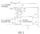
- a signal splitter 1 according to the present invention is shown to include a first connecting port 13, a second connecting port 12, a low-pass filter circuit 11, and a coupling circuit 14.
- the first connecting port 13 is adapted to be coupled to an incoming telephone line, and has first and second terminals 131, 132.
- the second connecting port 12 is adapted to be coupled to a telephony instrument, and has first and second terminals 121, 122.
- the low-pass filter circuit 11 has first and second input ends 111, 112 connected electrically and respectively to the first and second terminals 131, 132 of the first connecting port 13, and first and second output ends 113, 114 connected electrically and respectively to the first and second terminals 121, 122 of the second connecting port 12.
- the low-pass filter circuit 11 is capable of permitting a low-frequency component of an incoming signal in the incoming telephone line to pass therethrough to the second connecting port 12 in a known manner.
- the coupling circuit 14 includes a coupling transformer (T1) and a capacitor (C1).
- the coupling transformer (T1) includes a common core (not shown), a primary winding 141 that is wound on the common core and that interconnects the first terminal 131 of the first connecting port 13 and the first input end 111 of the low-pass filter circuit 11, and a secondary winding 142 that is wound on the common core and that interconnects the second terminal 122 of the second connecting port 12 and the second output end 114 of the low-pass filter circuit 11.
- a phase difference between a signal passing through the primary winding 141 and a signal passing through the secondary winding 142 is 180°.
- the capacitor (C1) is coupled between the first terminal 131 of the first connecting port 13 and the second terminal 122 of the second connecting port 12.
- the coupling circuit 14 is operable to generate a coupling signal at the second connecting port 12 based on a high-frequency component of the incoming signal in the incoming telephone line. At the same time, a high-frequency noise signal is induced by the high-frequency component of the incoming signal in the incoming telephone line upon the second connecting port 12. Since the coupling signal generated by the coupling circuit 14 has a magnitude substantially equal to that of the high-frequency noise signal induced upon the second connecting port 12, and since the phase difference between the coupling signal and the high-frequency noise signal is 180°, the high-frequency noise signal is cancelled by the coupling signal, thereby minimizing the effect of cross-talk phenomenon.
- the signal splitter 1 of this invention further includes a modem interface (not shown) for coupling with a DSL modem, such as an Asymmetric Digital Subscriber Line (ADSL) modem, an Integrated Digital Subscriber Line (IDSL) modem, a High-bit-rate Digital Subscriber Line (HDSL) modem, a Single-pair Digital Subscriber Line (SDSL) modem, a Very High Data Rate Subscriber Line (VDSL) modem, etc.
- the modem interface permits the high-frequency component of the incoming signal in the incoming telephone line to pass therethrough to the DSL modem. Since the feature of the invention does not reside in the conf iguration of the modem interface, which is conventional, details of the same are omitted herein for the sake of brevity.
Landscapes
- Engineering & Computer Science (AREA)
- Computer Networks & Wireless Communication (AREA)
- Signal Processing (AREA)
- Telephonic Communication Services (AREA)
- Filters And Equalizers (AREA)
Priority Applications (1)
| Application Number | Priority Date | Filing Date | Title |
|---|---|---|---|
| EP06019188A EP1901538A1 (fr) | 2006-09-13 | 2006-09-13 | Séparateur de signal |
Applications Claiming Priority (1)
| Application Number | Priority Date | Filing Date | Title |
|---|---|---|---|
| EP06019188A EP1901538A1 (fr) | 2006-09-13 | 2006-09-13 | Séparateur de signal |
Publications (1)
| Publication Number | Publication Date |
|---|---|
| EP1901538A1 true EP1901538A1 (fr) | 2008-03-19 |
Family
ID=37697889
Family Applications (1)
| Application Number | Title | Priority Date | Filing Date |
|---|---|---|---|
| EP06019188A Withdrawn EP1901538A1 (fr) | 2006-09-13 | 2006-09-13 | Séparateur de signal |
Country Status (1)
| Country | Link |
|---|---|
| EP (1) | EP1901538A1 (fr) |
Citations (3)
| Publication number | Priority date | Publication date | Assignee | Title |
|---|---|---|---|---|
| JPS60125902A (ja) * | 1983-12-09 | 1985-07-05 | Victor Co Of Japan Ltd | 磁気記録再生装置 |
| EP1076447A2 (fr) * | 1999-08-09 | 2001-02-14 | Excelsus Technologies, Inc. | Circuit de filtre de blocage d' impédance |
| GB2415571A (en) * | 2004-06-22 | 2005-12-28 | Ycl Electronic Co Ltd | Signal splitter |
-
2006
- 2006-09-13 EP EP06019188A patent/EP1901538A1/fr not_active Withdrawn
Patent Citations (3)
| Publication number | Priority date | Publication date | Assignee | Title |
|---|---|---|---|---|
| JPS60125902A (ja) * | 1983-12-09 | 1985-07-05 | Victor Co Of Japan Ltd | 磁気記録再生装置 |
| EP1076447A2 (fr) * | 1999-08-09 | 2001-02-14 | Excelsus Technologies, Inc. | Circuit de filtre de blocage d' impédance |
| GB2415571A (en) * | 2004-06-22 | 2005-12-28 | Ycl Electronic Co Ltd | Signal splitter |
Similar Documents
| Publication | Publication Date | Title |
|---|---|---|
| EP0923221B1 (fr) | Séparateur et filtre de signaux de communication | |
| US6704397B1 (en) | Filter arrangement | |
| JP4141707B2 (ja) | ブロードバンドモデムのためのハイブリッド回路 | |
| WO2008034643A1 (fr) | Ordre multiple de filtre passe-bas pour diviseur de type xdsl | |
| US7177349B2 (en) | High impedance state for digital subscriber line transceivers on copper twisted pairs | |
| EP1901538A1 (fr) | Séparateur de signal | |
| US7432782B2 (en) | Signal splitter | |
| US6757380B2 (en) | Impedance blocking filter circuit for digital subscriber line communication systems | |
| EP1901539A1 (fr) | Diviseur DSL | |
| EP2066103B1 (fr) | Séparateur xdsl à indépendance commutable | |
| CN1960196B (zh) | 一种电信滤波器设备 | |
| US6473507B1 (en) | Apparatus and method for isolating transients associated with a digital subscriber line | |
| US8249134B2 (en) | High impedance state for digital subscriber line transceivers on copper pairs | |
| WO2010040547A1 (fr) | Séparateur voix/données universel | |
| CN101155217A (zh) | 可降低串音现象的话音分离装置 | |
| EP1729472A2 (fr) | Appareil pour conditionner et séparer des signaux de télécommunication | |
| CN100449941C (zh) | 低频滤波装置 | |
| CN100559821C (zh) | 适合于adsl传输的用于电话线的滤波器 | |
| CN101155216A (zh) | 可降低串音现象的话音分离装置 | |
| JP4268821B2 (ja) | 信号処理装置 | |
| US20020141570A1 (en) | Low-pass filter usable with caller ID device | |
| AU2005200624B2 (en) | High performance micro-filter and splitter apparatus | |
| US20080074210A1 (en) | Signal splitter | |
| CN101154963A (zh) | 具有低通滤波补偿电路的话音分离装置 | |
| JP2004260610A (ja) | xDSL通信用線路特性改善方法及びそのための終端装置 |
Legal Events
| Date | Code | Title | Description |
|---|---|---|---|
| PUAI | Public reference made under article 153(3) epc to a published international application that has entered the european phase |
Free format text: ORIGINAL CODE: 0009012 |
|
| AK | Designated contracting states |
Kind code of ref document: A1 Designated state(s): AT BE BG CH CY CZ DE DK EE ES FI FR GB GR HU IE IS IT LI LT LU LV MC NL PL PT RO SE SI SK TR |
|
| AX | Request for extension of the european patent |
Extension state: AL BA HR MK YU |
|
| AKX | Designation fees paid | ||
| STAA | Information on the status of an ep patent application or granted ep patent |
Free format text: STATUS: THE APPLICATION IS DEEMED TO BE WITHDRAWN |
|
| 18D | Application deemed to be withdrawn |
Effective date: 20080920 |
|
| REG | Reference to a national code |
Ref country code: DE Ref legal event code: 8566 |