EP1901598B2 - Automatisierungsgerät - Google Patents
Automatisierungsgerät Download PDFInfo
- Publication number
- EP1901598B2 EP1901598B2 EP20060019090 EP06019090A EP1901598B2 EP 1901598 B2 EP1901598 B2 EP 1901598B2 EP 20060019090 EP20060019090 EP 20060019090 EP 06019090 A EP06019090 A EP 06019090A EP 1901598 B2 EP1901598 B2 EP 1901598B2
- Authority
- EP
- European Patent Office
- Prior art keywords
- bus module
- connection
- modules
- parts
- connection bus
- Prior art date
- Legal status (The legal status is an assumption and is not a legal conclusion. Google has not performed a legal analysis and makes no representation as to the accuracy of the status listed.)
- Not-in-force
Links
- 239000002775 capsule Substances 0.000 claims description 3
- 230000000712 assembly Effects 0.000 description 11
- 238000000429 assembly Methods 0.000 description 11
- 150000001875 compounds Chemical class 0.000 description 1
- 230000037431 insertion Effects 0.000 description 1
- 238000003780 insertion Methods 0.000 description 1
- 230000002093 peripheral effect Effects 0.000 description 1
Images

Classifications
-
- H—ELECTRICITY
- H05—ELECTRIC TECHNIQUES NOT OTHERWISE PROVIDED FOR
- H05K—PRINTED CIRCUITS; CASINGS OR CONSTRUCTIONAL DETAILS OF ELECTRIC APPARATUS; MANUFACTURE OF ASSEMBLAGES OF ELECTRICAL COMPONENTS
- H05K7/00—Constructional details common to different types of electric apparatus
- H05K7/14—Mounting supporting structure in casing or on frame or rack
- H05K7/1462—Mounting supporting structure in casing or on frame or rack for programmable logic controllers [PLC] for automation or industrial process control
- H05K7/1475—Bus assemblies for establishing communication between PLC modules
- H05K7/1478—Bus assemblies for establishing communication between PLC modules including a segmented bus
-
- H—ELECTRICITY
- H05—ELECTRIC TECHNIQUES NOT OTHERWISE PROVIDED FOR
- H05K—PRINTED CIRCUITS; CASINGS OR CONSTRUCTIONAL DETAILS OF ELECTRIC APPARATUS; MANUFACTURE OF ASSEMBLAGES OF ELECTRICAL COMPONENTS
- H05K7/00—Constructional details common to different types of electric apparatus
- H05K7/14—Mounting supporting structure in casing or on frame or rack
- H05K7/1462—Mounting supporting structure in casing or on frame or rack for programmable logic controllers [PLC] for automation or industrial process control
- H05K7/1465—Modular PLC assemblies with separable functional units
Definitions
- the invention relates to an automation device, which has a plurality of assemblies, with a housing capsule for each module, which is provided with at least one rear wall, and with an arranged on the rear wall of each module module bus module part, which is connected to a circuit board and which with a connection Bus module part electrically and mechanically cooperates, which establishes a bus connection with an adjacent module, wherein the modules are mounted on a mounting rail.
- Such an automation device is from the DE 42 25 573 C2 known.
- Each assembly of this automation device has a substantially U-shaped module bus module part, which is electrically and mechanically connected to produce a bus connection with an adjacent module with a likewise substantially U-shaped connection bus module part.
- the base and the legs of a connection bus module part bridge the distance between one leg of a module bus module part from an adjacent leg of an adjacent module.
- the assembly of the automation device is preferably carried out in such a way that in each case a leg of the connection bus module part is inserted into the right leg of the modules, so that the right leg of the respective connection bus module part protrudes from the back right of the modules. Subsequently, the assemblies nach- and side by side swung onto a mounting rail, forcibly by the pivoting the electrical connection of adjacent modules is made.
- EP 0 025 209 A2 describes a baseline arrangement which is provided for the electrical connection of assemblies.
- the present invention has for its object to provide an automation device of the type mentioned, the assembly is simplified.
- connection bus module parts carrier is z. B. initially positioned on the support rail and held by the swiveling of two modules on the support rail. By pivoting these assemblies, their subassembly bus module parts engage the corresponding link bus module parts of the carrier, thereby holding the carrier by these assemblies. On a carrier positioned and held in such a way then the remaining modules can be swung open. A pre-assembly of a connection Busmodulteils before swiveling an assembly is no longer required. It is also particularly advantageous that individual connection bus module parts can not be lost in the event of disassembly of modules, since each connection bus module part is held in position on the carrier and new modules can be inserted or swung onto these connection bus module parts.
- the length of the carrier can be easily adapted to the number of required modules of the programmable controller.
- a carrier according to the measures specified in claim 2 prevents z.
- a service technician carry a variety of connection bus module parts separately or that a customer must store a variety of items in the form of individual connection bus module parts in a spare parts inventory.
- Such a carrier is easier to handle and easier to market as a separate part.
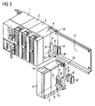
- FIG. 3 in which a known per se modular automation device is shown.
- This has modules 1 to 5, of which the module 1 is a central unit and the modules 2 to 5 are designed as peripheral modules.
- Each of the assemblies 1 to 5 is provided with a substantially U-shaped module bus module part 6, which is electrically connected to a printed circuit board 7 and electrically and mechanically with a substantially symmetrically constructed U-shaped connection bus module part 8 in assembled automation device Active compound is.
- the modules 1 to 5 are designed to protect against damage to the circuit board contained in the modules 1 to 5 7 as enveloping housing capsule.
- Each leg 8 ', 8 "of the connection bus module part 8 can be inserted into each leg 6', 6" of the module bus module part 6, whereby a bus connection is created.
- the module bus module part 6 is designed such that the legs 6 ', 6 '' always have the same distance to the nearest side wall, eg the side walls 5 ', 5''of the assembly 5, independently of the width of the assemblies, eg the assembly 5.
- the connection bus module part 8 is designed so that it is exactly the distance between two The assembly of the automation device takes place, for example, in such a way that the left leg 8 'of the connection bus module part 8 is inserted into the right leg 6 "of the assemblies 1 to 5 in each case so that the right leg 8 "of the respective connection bus module part 8 protrudes to the right rear from the assemblies 1 to 5.
- the assemblies 1 to 5 are moved back and forth by means of a hooking device 10 arranged on a rear wall 9 of the assemblies 1 to 5 pivoted onto a mounting rail 11, wherein the electrical connection of adjacent modules is forcibly produced by the swiveling, wherein after swiveling the modules 1 to 5 are secured by a screw 12 on the support rail 11.
- the bus connection is thus constructed by alternately each one Module Busmodulteil 6 and a connection Busmodulteil 8 electrically and mechanically miteinan which are connected. Insertion of a connection bus module part into an assembly before swiveling this assembly can be dispensed with by placing and holding the connection bus module parts on a support.
- FIG. 1 In this context is on FIG. 1 referenced, in which a modular automation device is shown.
- the in the FIGS. 1 and 3 The same parts shown are provided with the same reference numerals.
- the connection bus module parts are held on a support 13, which is arranged on the support rail 11.
- the carrier can be positioned in a simple manner on the mounting rail 11, for example by the modules 1 and 4 plugged onto the corresponding connection bus module parts 8 and then the modules 1 and 4 are pivoted to the support 13 on the support rail 11.
- the carrier 13 is positioned on the support rail 11 and it can be pivoted on the support rail 11, the remaining modules, forcibly by the pivoting the electrical connection of adjacent modules is made.
- the carrier 13 is provided with predetermined breaking points, whereby the length of the carrier 13 can be easily adapted to the number of required modules of the programmable controller.
- the carrier 13 has seven connection bus module parts and the support rail 11 is thus provided for receiving eight modules.
- connection bus module parts 8 are z. B. on a support in the form of a plastic strip 14 ( FIG. 2 ) glued, which can be rolled up spirally and which is provided with predetermined breaking points 15 in a grid spacing.
- a plastic strip 14 FIG. 2
- the modules can be disassembled without loss of connection bus module parts 8.
Landscapes
- Engineering & Computer Science (AREA)
- Automation & Control Theory (AREA)
- Microelectronics & Electronic Packaging (AREA)
- Coupling Device And Connection With Printed Circuit (AREA)
- Manufacturing Of Electrical Connectors (AREA)
Description
- Die Erfindung betrifft ein Automatisierungsgerät, welches mehrere Baugruppen aufweist, mit einer Gehäusekapsel für jede Baugruppe, die mit wenigstens einer Rückwand versehen ist, und mit einem an der Rückwand jeder Baugruppe angeordneten Baugruppen-Busmodulteil, welches mit einer Leiterplatte verbunden ist und welches mit einem Verbindungs-Busmodulteil elektrisch und mechanisch zusammenwirkt, das eine Busverbindung mit einer benachbarten Baugruppe herstellt, wobei die Baugruppen auf eine Tragschiene montiert sind.
- Ein derartiges Automatisierungsgerät ist aus der
DE 42 25 573 C2 bekannt. Jede Baugruppe dieses Automatisierungsgerätes weist ein im Wesentlichen U-förmiges Baugruppen-Busmodulteil auf, welches zur Herstellung einer Busverbindung mit einer benachbarten Baugruppe mit einem ebenfalls im Wesentlichen U-förmigen Verbindungs-Busmodulteil elektrisch und mechanisch verbunden ist. Die Basis und die Schenkel eines Verbindungs-Busmodulteils überbrücken dabei den Abstand zwischen einem Schenkel eines Baugruppen-Busmodulteils von einem benachbarten Schenkel einer benachbarten Baugruppe. Der Zusammenbau des Automatisierungsgerätes erfolgt vorzugsweise in der Art und Weise, dass jeweils in den rechten Schenkel der Baugruppen ein Schenkel des Verbindungs-Busmodulteils eingesetzt wird, so dass der rechte Schenkel des jeweiligen Verbindungs-Busmodulteils rechts hinten aus den Baugruppen hervorragt. Anschließend werden die Baugruppen nach- und nebeneinander auf eine Tragschiene aufgeschwenkt, wobei durch das Aufschwenken zwangsweise die elektrische Verbindung benachbarter Baugruppen hergestellt wird. -
EP 0 025 209 A2 beschreibt eine Basline-Anordnung, welche zur elektrischen Verbindung von Baugruppen vorgesehen ist. - Der vorliegenden Erfindung liegt die Aufgabe zugrunde, ein Automatisierungsgerät der eingangs genannten Art zu schaffen, dessen Zusammenbau vereinfacht wird.
- Diese Aufgabe wird durch die im kennzeichnenden Teil des Anspruchs 1 angegebenen Maßnahmen gelöst.
- Durch einen derartigen Träger wird eine Montage der Baugruppen vereinfacht. Der mit den Verbindungs-Busmodulteilen versehene Träger wird z. B. zunächst an der Tragschiene positioniert und durch das Aufschwenken von zwei Baugruppen auf der Tragschiene festgehalten. Durch das Aufschwenken dieser Baugruppen greifen deren Baugruppen-Busmodulteile in die entsprechenden Verbindungs-Busmodulteile des Trägers ein, wodurch der Träger durch diese Baugruppen festgehalten wird. Auf einen derartig positionierten und festgehaltenen Träger können anschließend die restlichen Baugruppen aufgeschwenkt werden. Eine Vormontage eines Verbindungs-Busmodulteils vor dem Aufschwenken einer Baugruppe ist nicht mehr erforderlich. Besonders vorteilhaft ist ferner, dass einzelne Verbindungs-Busmodulteile im Falle einer Demontage von Baugruppen nicht verloren gehen können, da jedes Verbindungs-Busmodulteil auf dem Träger in seiner Position gehalten wird und auf diese Verbindungs-Busmodulteile neue Baugruppen gesteckt bzw. aufgeschwenkt werden können.
- Dadurch, dass der Träger mit Sollbruchstellen versehen ist kann die Länge des Trägers leicht an die Anzahl der benötigten Baugruppen des Automatisierungsgerätes angepasst werden.
- Durch einen Träger gemäß den im Anspruch 2 angegebenen Maßnahmen wird vermieden, dass z. B. ein Servicetechniker eine Vielzahl von Verbindungs-Busmodulteilen separat mitführen bzw. dass ein Kunde im Rahmen einer Ersatzteilhaltung eine Vielzahl von Einzelteilen in Form von einzelnen Verbindungs-Busmodulteilen lagern muss. Ein derartiger Träger ist einfacher zu handhaben und einfacher als separates Teil zu vermarkten.
- Anhand der Zeichnung, in der ein Ausführungsbeispiel der Erfindung veranschaulicht ist, werden im Folgenden die Erfindung, deren Ausgestaltungen sowie Vorteile näher erläutert.
- Es zeigen in schematischer Darstellung:
- Figur 1
- ein modulares Automatisierungsgerät mit einem Verbindungs-Busmodulteile aufweisenden Träger,
- Figur 2
- auf einem Träger gehaltene Verbindungs-Busmodulteile und
- Figur 3
- ein bekanntes modulares Automatisierungsgerät.
- Es wird zunächst auf
Figur 3 verwiesen, in welcher ein an sich bekanntes modulares Automatisierungsgerät dargestellt ist. Dieses weist Baugruppen 1 bis 5 auf, von denen die Baugruppe 1 eine Zentraleinheit ist und die Baugruppen 2 bis 5 als Peripheriebaugruppen ausgestaltet sind. Jede der Baugruppen 1 bis 5 ist mit einem im Wesentlichen U-förmigen Baugruppen-Busmodulteil 6 versehen, welches mit einer Leiterplatte 7 elektrisch verbunden ist und mit einem dazu im Wesentlichen symmetrisch aufgebauten U-förmigen Verbindungs-Busmodulteil 8 bei zusammengebautem Automatisierungsgerät elektrisch und mechanisch in Wirkverbindung steht. Die Baugruppen 1 bis 5 sind zum Schutz vor Beschädigung der in den Baugruppen 1 bis 5 enthaltenen Leiterplatte 7 als umhüllende Gehäusekapsel ausgebildet. Jeder Schenkel 8', 8'' des Verbindungs-Busmodulteils 8 kann in jeden Schenkel 6', 6" des Baugruppen-Busmodulteils 6 eingesetzt werden, wodurch eine Busverbindung entsteht. Das Baugruppen-Busmodulteil 6 ist derart ausgestaltet, dass die Schenkel 6', 6'' unabhängig von der Breite der Baugruppen, z. B. der Baugruppe 5, stets den gleichen Abstand zur nächstliegenden Seitenwand, z. B. den Seitenwänden 5', 5'' der Baugruppe 5, aufweisen. Das Verbindungs-Busmodulteil 8 ist derart ausgestaltet, dass es genau den Abstand zwischen zwei Schenkeln 6', 6" zweier benachbarter Baugruppen überbrückt. Der Zusammenbau des Automatisierungsgerätes erfolgt z. B. in der Art und Weise, dass jeweils in den rechten Schenkel 6" der Baugruppen 1 bis 5 der linke Schenkel 8' des Verbindungs-Busmodulteils 8 eingesetzt wird, so dass der rechte Schenkel 8" des jeweiligen Verbindungs-Busmodulteils 8 rechts hinten aus den Baugruppen 1 bis 5 hervorragt. Anschließend werden die Baugruppen 1 bis 5 mittels einer an einer Rückwand 9 der Baugruppen 1 bis 5 angeordneten Hakvorrichtung 10 nach- und nebeneinander auf eine Tragschiene 11 aufgeschwenkt, wobei durch das Aufschwenken zwangsweise die elektrische Verbindung benachbarter Baugruppen hergestellt wird, wobei nach dem Aufschwenken die Baugruppen 1 bis 5 durch eine Schraubverbindung 12 auf der Tragschiene 11 gesichert werden. Die Busverbindung wird also dadurch aufgebaut, dass abwechselnd je ein Baugruppen-Busmodulteil 6 und ein Verbindungs-Busmodulteil 8 elektrisch und mechanisch miteinander verbunden sind.
Auf ein Einsetzen eines Verbindungs-Busmodulteils in eine Baugruppe vor dem Aufschwenken dieser Baugruppe kann verzichtet werden, indem die Verbindungs-Busmodulteile auf einen Träger angeordnet und auf diesem gehalten werden. - In diesem Zusammenhang wird auf
Figur 1 verwiesen, in welcher ein modulares Automatisierungsgerät dargestellt ist. Die in denFiguren 1 und3 dargestellten gleichen Teile sind mit gleichen Bezugszeichen versehen. Die Verbindungs-Busmodulteile werden auf einem Träger 13 gehalten, der auf der Tragschiene 11 angeordnet ist. Der Träger kann in einfacher Weise auf der Tragschiene 11 positioniert werden, indem beispielsweise die Baugruppen 1 und 4 auf die entsprechenden Verbindungs-Busmodulteile 8 gesteckt und anschließend die Baugruppen 1 und 4 mit dem Träger 13 auf die Tragschiene 11 aufgeschwenkt werden. Dadurch ist der Träger 13 auf der Tragschiene 11 positioniert und es können die restlichen Baugruppen auf die Tragschiene 11 aufgeschwenkt werden, wobei durch das Aufschwenken zwangsweise die elektrische Verbindung benachbarter Baugruppen hergestellt wird. Der Träger 13 ist mit Sollbruchstellen versehen, wodurch die Länge des Trägers 13 leicht an die Anzahl der benötigten Baugruppen des Automatisierungsgerätes angepasst werden kann. Im dargestellten Ausführungsbeispiel weist der Träger 13 sieben Verbindungs-Busmodulteile auf und die Tragschiene 11 ist somit zur Aufnahme von acht Baugruppen vorgesehen. - Durch den Träger wird vermieden, dass einerseits ein Servicetechniker eine Vielzahl von Verbindungs-Busmodulteilen separat mitführen und dass andererseits ein Kunde im Rahmen einer Ersatzteilhaltung eine Vielzahl von Einzelteilen in Form von einzelnen Verbindungs-Busmodulteilen lagern muss. Die Verbindungs-Busmodulteile 8 sind z. B. auf einem Träger in Form eines Kunststoffstreifens 14 (
Figur 2 ) angeklebt, welcher spiralförmig aufgerollt sein kann und welcher in einem Rasterabstand mit Sollbruchstellen 15 versehen ist. Dadurch ist es im Rahmen einer Montage vor Ort leicht möglich, einen Streifen mit einer gewünschten Anzahl von Verbindungs-Busmodulteilen 8 abzubrechen. Die Baugruppen können demontiert werden, ohne dass dabei Verbindungs-Busmodulteile 8 verloren gehen.
Claims (2)
- Automatisierungsgerät, welches mehrere Baugruppen (1, 2, ...) aufweist, mit- einer Gehäusekapsel für jede Baugruppe (1, 2, ...), die mit wenigstens einer Rückwand (9) versehen ist,- einem an der Rückwand (9) jeder Baugruppe (1, 2, ...) angeordneten Baugruppen-Busmodulteil (6), welches mit einer Leiterplatte (7) verbunden ist und welches mit einem Verbindungs-Busmodulteil (8) elektrisch und mechanisch zusammenwirkt, das eine Busverbindung mit einer benachbarten Baugruppe herstellt, wobei die Baugruppen-Busmodulteile (6) und die Verbindungs-Busmodulteile (8) im Wesentlichen U-förmig sind und zwei Schenkel (6', 6"; 8', 8" ) und eine Basis sowie mehrere Buskontakte aufweisen,wobei die Baugruppen (1, 2, ...) auf eine Tragschiene (11) montiert sind,
dadurch gekennzeichnet,- dass die Verbindungs-Busmodulteile (8) auf einem auf der Tragschiene (11) angeordneten Träger (13; 14) gehalten sind, wobei jeweils die Basis der im Wesentlichen U-förmigen Verbindungs-Busmodulteile (8) auf dem Träger (13; 14) befestigt ist, und- dass der Träger (13; 14) mit Sollbruchstellen (15) versehen ist. - Träger mit mehreren Verbindungs-Busmodulteilen (8), welcher für einen Einsatz in einem Automatisierungsgerät nach Anspruch 1 geeignet ist, dadurch gekennzeichnet, dass der Träger (13; 14) mit Sollbruchstellen (15) versehen ist.
Priority Applications (2)
| Application Number | Priority Date | Filing Date | Title |
|---|---|---|---|
| DE200650002027 DE502006002027D1 (de) | 2006-09-12 | 2006-09-12 | Automatisierungsgerät |
| EP20060019090 EP1901598B2 (de) | 2006-09-12 | 2006-09-12 | Automatisierungsgerät |
Applications Claiming Priority (1)
| Application Number | Priority Date | Filing Date | Title |
|---|---|---|---|
| EP20060019090 EP1901598B2 (de) | 2006-09-12 | 2006-09-12 | Automatisierungsgerät |
Publications (3)
| Publication Number | Publication Date |
|---|---|
| EP1901598A1 EP1901598A1 (de) | 2008-03-19 |
| EP1901598B1 EP1901598B1 (de) | 2008-11-05 |
| EP1901598B2 true EP1901598B2 (de) | 2012-02-29 |
Family
ID=37943837
Family Applications (1)
| Application Number | Title | Priority Date | Filing Date |
|---|---|---|---|
| EP20060019090 Not-in-force EP1901598B2 (de) | 2006-09-12 | 2006-09-12 | Automatisierungsgerät |
Country Status (2)
| Country | Link |
|---|---|
| EP (1) | EP1901598B2 (de) |
| DE (1) | DE502006002027D1 (de) |
Families Citing this family (6)
| Publication number | Priority date | Publication date | Assignee | Title |
|---|---|---|---|---|
| EP2157845A1 (de) | 2008-08-13 | 2010-02-24 | Siemens Aktiengesellschaft | Automatisierungsgerät |
| DE102010062065A1 (de) | 2010-11-26 | 2012-05-31 | Siemens Aktiengesellschaft | Modulares Elektronikgerät |
| ES2683886T3 (es) | 2013-06-27 | 2018-09-28 | Siemens Aktiengesellschaft | Aparato de comunicaciones modular para un sistema de automatización industrial |
| DE102013112117A1 (de) * | 2013-11-04 | 2015-05-07 | Phoenix Contact Gmbh & Co. Kg | Funktionskomponente für ein Komponentenaufbausystem |
| DE102013112099B4 (de) * | 2013-11-04 | 2021-10-07 | Phoenix Contact Gmbh & Co. Kg | Komponentenaufbausystem |
| JP5983696B2 (ja) * | 2014-01-29 | 2016-09-06 | 横河電機株式会社 | 電子機器 |
Family Cites Families (9)
| Publication number | Priority date | Publication date | Assignee | Title |
|---|---|---|---|---|
| DE2936621A1 (de) | 1979-09-11 | 1981-03-26 | Brown, Boveri & Cie Ag, 6800 Mannheim | Buslinie-anordnung fuer elektronik-systeme in blockbauform |
| US4790762A (en) * | 1985-07-23 | 1988-12-13 | Honeywell Inc. | Backplane for a modularly expandable programmable controller |
| FR2608847B1 (fr) * | 1986-12-19 | 1989-04-21 | Legrand Sa | Connecteur de liaison pour appareil electrique a mise en place par encliquetage sur un rail de montage, et appareil electrique propre a la mise en oeuvre d'un tel connecteur de liaison |
| DE3740290C2 (de) * | 1987-11-27 | 1997-01-16 | Licentia Gmbh | Vorrichtung zum Steuern und/oder Regeln von Prozessen |
| DE8804649U1 (de) * | 1988-04-08 | 1988-06-16 | Murrelektronik GmbH, 7155 Oppenweiler | Elektrisches Gerät, z.B. Schaltgerät, Einschaltverzögerer od. dgl. |
| ATE95969T1 (de) * | 1988-10-18 | 1993-10-15 | Weidmueller Interface | Mehrfachsignaluebertragungsgeraet. |
| EP0527247B1 (de) * | 1991-08-08 | 2000-02-02 | Siemens Aktiengesellschaft | Selbstaufbauender Bus |
| DE19610559A1 (de) * | 1996-03-18 | 1997-09-25 | Siemens Ag | Speicherprogrammierbare Steuerung |
| DE10134885B4 (de) * | 2001-07-18 | 2004-02-05 | Roche Diagnostics Gmbh | Modulares Analysesystem |
-
2006
- 2006-09-12 EP EP20060019090 patent/EP1901598B2/de not_active Not-in-force
- 2006-09-12 DE DE200650002027 patent/DE502006002027D1/de active Active
Also Published As
| Publication number | Publication date |
|---|---|
| EP1901598A1 (de) | 2008-03-19 |
| DE502006002027D1 (de) | 2008-12-18 |
| EP1901598B1 (de) | 2008-11-05 |
Similar Documents
| Publication | Publication Date | Title |
|---|---|---|
| DE102004031707B4 (de) | Intelligenter Anschlusskasten für Kraftfahrzeuge | |
| DE4419895C2 (de) | Verbindungsanordnung in einer Kabelbaum-Montagegruppe für Fahrzeuge | |
| EP0527247B1 (de) | Selbstaufbauender Bus | |
| EP2115841B1 (de) | Tragvorrichtung für stromsammelschienen | |
| EP3461376B1 (de) | Einrichtung zur warenpräsentation und adapter für eine solche einrichtung | |
| DE102012014775A1 (de) | Vorrichtung zur Anordnung von Batteriemodulen in einer Fahrzeugbatterie | |
| EP1901598B2 (de) | Automatisierungsgerät | |
| DE102010039133A1 (de) | Halterungsanordnung zur Halterung von Systemen sowie Luft- oder Raumfahrzeug | |
| DE19901962B4 (de) | Verfahren zum Montieren elektrischer Steckverbindungen sowie Montagehilfe zur Verfahrensdurchführung | |
| DE202015101776U1 (de) | Rangierwabe | |
| EP3084902B1 (de) | Rahmen für einen schaltschrank mit demontierbarer bodenplatte für verteilsammelschienen sowie herstellungsverfahren für einen schaltschrank | |
| DE2847116C2 (de) | Kabelverbindung für Wählvermittlungsanlagen | |
| EP3281253B1 (de) | Rangierwabe | |
| EP2036176A1 (de) | Stromschienenhalter und stromverteilereinheit mit einem stromschienenhalter | |
| DE69605271T2 (de) | Verfahren zur Herstellung von flexiblen gedruckten Leiterplatten, insbesondere für Motorfahrzeuge, und dabei hergestellte gedruckte Leiterplatten | |
| DE102013222090A1 (de) | Zellkontaktierungssystem, Batteriemodul mit einem Zellkontaktierungssystem und Fahrzeug mit zumindest einem derartigen Batteriemodul | |
| EP1605269B1 (de) | Zählerplatz | |
| DE19518220B4 (de) | Ausziehvorrichtung für einen Telekommunikationsgeräterahmen | |
| EP1728310A1 (de) | Langstator mit einer erdungsleitung und damit ausgerüstete magnetschwebebahn | |
| EP1713315A2 (de) | Anordnung elektrischer bzw. elektronischer Geräte | |
| DE1224371B (de) | Gestellverdrahtung fuer Fernmeldeanlagen, insbesondere fuer Gestelle von Fernsprech-vermittlungsschraenken | |
| DE10316384A1 (de) | Kontaktadapter für die Kontaktierung einer Antennenstruktur eines Fahrzeuges | |
| DE4339095A1 (de) | Lenkstockschalter für Kraftfahrzeuge | |
| DE9418719U1 (de) | Elektrische Verbindungsvorrichtung | |
| EP0394753B1 (de) | Codiervorrichtung für auf eine Rückwandverdrahtung aufsteckbare elektrische Baugruppen |
Legal Events
| Date | Code | Title | Description |
|---|---|---|---|
| PUAI | Public reference made under article 153(3) epc to a published international application that has entered the european phase |
Free format text: ORIGINAL CODE: 0009012 |
|
| 17P | Request for examination filed |
Effective date: 20070720 |
|
| AK | Designated contracting states |
Kind code of ref document: A1 Designated state(s): AT BE BG CH CY CZ DE DK EE ES FI FR GB GR HU IE IS IT LI LT LU LV MC NL PL PT RO SE SI SK TR |
|
| AX | Request for extension of the european patent |
Extension state: AL BA HR MK YU |
|
| GRAP | Despatch of communication of intention to grant a patent |
Free format text: ORIGINAL CODE: EPIDOSNIGR1 |
|
| GRAS | Grant fee paid |
Free format text: ORIGINAL CODE: EPIDOSNIGR3 |
|
| GRAA | (expected) grant |
Free format text: ORIGINAL CODE: 0009210 |
|
| AK | Designated contracting states |
Kind code of ref document: B1 Designated state(s): DE FR GB IT |
|
| REG | Reference to a national code |
Ref country code: GB Ref legal event code: FG4D Free format text: NOT ENGLISH |
|
| AKX | Designation fees paid |
Designated state(s): DE FR GB IT |
|
| REF | Corresponds to: |
Ref document number: 502006002027 Country of ref document: DE Date of ref document: 20081218 Kind code of ref document: P |
|
| PLBI | Opposition filed |
Free format text: ORIGINAL CODE: 0009260 |
|
| PLAX | Notice of opposition and request to file observation + time limit sent |
Free format text: ORIGINAL CODE: EPIDOSNOBS2 |
|
| 26 | Opposition filed |
Opponent name: VIPA G Effective date: 20090805 |
|
| PLAF | Information modified related to communication of a notice of opposition and request to file observations + time limit |
Free format text: ORIGINAL CODE: EPIDOSCOBS2 |
|
| PLBB | Reply of patent proprietor to notice(s) of opposition received |
Free format text: ORIGINAL CODE: EPIDOSNOBS3 |
|
| PUAH | Patent maintained in amended form |
Free format text: ORIGINAL CODE: 0009272 |
|
| STAA | Information on the status of an ep patent application or granted ep patent |
Free format text: STATUS: PATENT MAINTAINED AS AMENDED |
|
| 27A | Patent maintained in amended form |
Effective date: 20120229 |
|
| AK | Designated contracting states |
Kind code of ref document: B2 Designated state(s): DE FR GB IT |
|
| REG | Reference to a national code |
Ref country code: DE Ref legal event code: R102 Ref document number: 502006002027 Country of ref document: DE Effective date: 20120229 |
|
| PGFP | Annual fee paid to national office [announced via postgrant information from national office to epo] |
Ref country code: DE Payment date: 20141120 Year of fee payment: 9 |
|
| REG | Reference to a national code |
Ref country code: FR Ref legal event code: PLFP Year of fee payment: 10 |
|
| PGFP | Annual fee paid to national office [announced via postgrant information from national office to epo] |
Ref country code: GB Payment date: 20150909 Year of fee payment: 10 |
|
| PGFP | Annual fee paid to national office [announced via postgrant information from national office to epo] |
Ref country code: FR Payment date: 20150910 Year of fee payment: 10 |
|
| PGFP | Annual fee paid to national office [announced via postgrant information from national office to epo] |
Ref country code: IT Payment date: 20150924 Year of fee payment: 10 |
|
| REG | Reference to a national code |
Ref country code: DE Ref legal event code: R119 Ref document number: 502006002027 Country of ref document: DE |
|
| PG25 | Lapsed in a contracting state [announced via postgrant information from national office to epo] |
Ref country code: DE Free format text: LAPSE BECAUSE OF NON-PAYMENT OF DUE FEES Effective date: 20160401 |
|
| GBPC | Gb: european patent ceased through non-payment of renewal fee |
Effective date: 20160912 |
|
| REG | Reference to a national code |
Ref country code: FR Ref legal event code: ST Effective date: 20170531 |
|
| PG25 | Lapsed in a contracting state [announced via postgrant information from national office to epo] |
Ref country code: FR Free format text: LAPSE BECAUSE OF NON-PAYMENT OF DUE FEES Effective date: 20160930 Ref country code: GB Free format text: LAPSE BECAUSE OF NON-PAYMENT OF DUE FEES Effective date: 20160912 |
|
| PG25 | Lapsed in a contracting state [announced via postgrant information from national office to epo] |
Ref country code: IT Free format text: LAPSE BECAUSE OF NON-PAYMENT OF DUE FEES Effective date: 20160912 |