EP1901643B1 - Medizinischer apparat und medizinisches system - Google Patents
Medizinischer apparat und medizinisches system Download PDFInfo
- Publication number
- EP1901643B1 EP1901643B1 EP05748201.0A EP05748201A EP1901643B1 EP 1901643 B1 EP1901643 B1 EP 1901643B1 EP 05748201 A EP05748201 A EP 05748201A EP 1901643 B1 EP1901643 B1 EP 1901643B1
- Authority
- EP
- European Patent Office
- Prior art keywords
- antenna devices
- medical apparatus
- programmer
- antenna
- signals
- Prior art date
- Legal status (The legal status is an assumption and is not a legal conclusion. Google has not performed a legal analysis and makes no representation as to the accuracy of the status listed.)
- Expired - Lifetime
Links
Images

Classifications
-
- A—HUMAN NECESSITIES
- A61—MEDICAL OR VETERINARY SCIENCE; HYGIENE
- A61N—ELECTROTHERAPY; MAGNETOTHERAPY; RADIATION THERAPY; ULTRASOUND THERAPY
- A61N1/00—Electrotherapy; Circuits therefor
- A61N1/18—Applying electric currents by contact electrodes
- A61N1/32—Applying electric currents by contact electrodes alternating or intermittent currents
- A61N1/36—Applying electric currents by contact electrodes alternating or intermittent currents for stimulation
- A61N1/372—Arrangements in connection with the implantation of stimulators
- A61N1/37211—Means for communicating with stimulators
- A61N1/37217—Means for communicating with stimulators characterised by the communication link, e.g. acoustic or tactile
- A61N1/37223—Circuits for electromagnetic coupling
- A61N1/37229—Shape or location of the implanted or external antenna
-
- A—HUMAN NECESSITIES
- A61—MEDICAL OR VETERINARY SCIENCE; HYGIENE
- A61B—DIAGNOSIS; SURGERY; IDENTIFICATION
- A61B5/00—Measuring for diagnostic purposes; Identification of persons
- A61B5/0002—Remote monitoring of patients using telemetry, e.g. transmission of vital signals via a communication network
- A61B5/0031—Implanted circuitry
Definitions
- the present invention relates to the field of telemetry, and in particular to a medical apparatus for programming and/or monitoring an implantable medical device over a radio-based wireless network, and such a system.
- Telemetry is a generic term for techniques for conveying measuring data from one point to another, usually by means of radio.
- medical field telemetry systems are generally used for enabling radio-frequency (RF) communication between an implantable medical device (IMD) such as a pacemaker, and an external monitoring device.
- IMD implantable medical device
- the frequency spectrum used for wireless communications between implanted medical devices and external equipment is about 400 MHz, but for wireless medical telemetry services in general several frequency bands may be used.
- Within a medical telemetry system crucial physiologic data is transmitted, and it is critical to ensure that data is not lost or delayed.
- Medical telemetry is a low-power radio system, and although relatively short distances are usually employed within such systems, there may nevertheless arise a need for considering reception aspects.
- One such consideration is related to the fact that electromagnetic fields emitted in a room will give rise to standing wave patterns.
- the energy that a receiver will be able to receive is varying as a function of the position in the room.
- US 2002/0013518 discloses a wireless patient monitor adapted to communicate with a medical telemetry network having a central station.
- the monitor includes sensor inputs for receiving vital signs data that is communicated to the central station over the telemetry network.
- US 6,167,312 discloses such a device for use in communication with an implantable medical device.
- the device is provided with a spatial diversity antenna array including at least one antenna permanently and fixedly mounted to the housing of a monitor or programmer, and an additional antenna removably mounted to the housing.
- the system comprises a removable antenna, but the use of it entails the physician having to move the antenna around until an acceptable reception is obtained. Therefore, should there arise a need to move a patient from one place to another, for example from an examination room to an X-ray examination room, the tedious reception/transmission optimization would have to be performed once more.
- the apparatus described requires the physician operating it to perform a kind of an antenna reception optimization, which is a time-consuming and also unreliable method.
- the range of said removable antenna is limited, and dependent upon the length of a coiled cord by means of which the removable antenna is coupled to a transceiver within the programmer.
- Such a programmer is relatively expensive, and it would be desirable and convenient to be able to easily move the programmer, for example between different wards in a hospital, with retained communication quality, to thereby avoid having to buy several costly programmers.
- a medical apparatus comprising a monitoring device and at least two antenna devices, the medical apparatus enabling programming and/or monitoring of an implantable medical device over a radio- based wireless network.
- the at least two antenna devices comprised within the system are provided as separate, stand-alone units, i.e. not forming part of the programmer or monitoring device. Thereby it is possible to place the antenna devices in an optimal way, preferably at stationary locations, such as for example wall and/or ceiling mounted.
- the antennas may be placed in each room, or area of use, in which telemetry is utilized, for example an X-ray room, examination room or operating room, or even in the equipment utilized.
- the programmer may be easily moved from one place to another without thereby affecting the signal quality.
- the placement of the antennas may also be optimized in advance, in consideration of where in the respective rooms the patient usually is located.
- the medical apparatus of the present invention further comprises a control unit provided for measuring a signal quality parameter of signals received from the implantable medical device by each of the antenna devices. Thereafter one of the antenna devices is selected for subsequent reception or transmission of signals from the implantable medical device depending on the measured signal quality parameter of the received signals. Spatial diversity is thereby ensured, and the antenna giving the best reception may be chosen and a reliable communication is provided.
- the signal quality parameter is any of RSSI, BER, or C/N ratio.
- control unit is utilized for measuring a signal quality parameter of signals received from the implantable medical device by each of the antenna devices at regular intervals, or continuously. It is thereby possible to rapidly detect a deteriorated signal quality and switch to an antenna having a better signal reception.
- control unit is connected between the programmer or monitoring device and the antenna devices.
- control unit is an integral part of the programmer.
- control unit is provided as an integral part of either one of the antenna devices. This provides a modular structure, giving a great design flexibility, and enabling custom-made solutions.
- the communication links between the programmer or monitoring device and the control unit on one hand, and between the control unit and the antenna devices on the other hand may be via wire, e.g. an USB connection, or wirelessly, e.g. via Bluetooth. This again adds to the design flexibility.
- each of the antenna devices comprises a radio transceiver unit.
- only one transceiver unit is provided, preferably centrally located in a room, or other area of use. Utilizing several radio transceiver units provides an additional security, but if a less expensive solution is desired, a fewer number of radio transceiver units may be provided.
- each of the antenna devices are fixedly mounted, for example in a ceiling or to a wall.
- the antenna devices may be more or less permanently placed at locations considered to be the best in view of reception/transmission from and to an implantable medical device.
- the reception/transmission may be optimized in advance, in dependence of an expected location in a room of the patient wearing the implantable medical device.
- each of the antenna devices comprises a conductive radiating antenna element, and these conductive radiating antenna elements are adapted to emit and receive radio waves having essentially parallel polarization. Thereby spatial diversity is provided independently of polarization diversity.
- each of the antenna devices comprises at least one conductive radiating antenna element capable of emitting and receiving radio waves of orthogonal polarizations. If at least two conductive radiating antenna elements are provided in each antenna device they should be operatively provided adjacent to each other at a single location in space.
- the programmer or monitoring device is portable, and is in particular a hand held device.
- the antenna devices are not physically part of the programmer or monitoring device, which would, considering the frequencies in question, require a certain, non-portable size of the programmer in order to accommodate the fastening of several antennas to it. The size of the programmer may therefore be reduced in accordance with the invention. A user may thereby easily bring the programmer along, should such need arise.
- the programmer or monitoring device is arranged on a movable rack such as a roller table or the like, whereby the present invention may be utilized also in connection with currently used programmer or monitoring devices, giving a solution easy to implement with existing programmers.
- the present invention is also related to such a system, in accordance with which advantages corresponding to the above described are achieved.
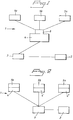
- a medical apparatus 1 for programming and/or monitoring a patient related device (not shown), for example an implantable medical device, over a radio-based wireless network comprises a programmer or monitoring device 2, hereinafter referred to as a programmer 2.
- the programmer 2 is provided with input and/or output means for transmitting programming instructions to an implantable medical device, and/or for outputting monitoring information patient related data, for example for display on a screen, thereby enabling a physician to easily see such patient related data received from the implantable medical device.
- a control unit 3 for example a microcontroller, is connected to the programmer 2, via wired standards, for example via USB (Universal Serial Bus), or via some wireless protocols.
- Bluetooth is such an exemplary, preferred wireless protocol, being an open-standard protocol.
- Using an open-standard protocol allows interoperability among devices from different manufacturers, which may be very advantageous in some cases.
- utilizing Bluetooth standard for communication between the programmer 2 and antenna devices may permit the use of programmers from different producers, without also necessitating antenna device changes, which is particularly advantageous if the antenna devices are wall mounted or in some other manner more permanently mounted.
- the control unit 3 and the programmer 2 are shown as separate parts, but it is possible to, in an alternative embodiment, make the control unit 3 an integrated part of the programmer 2.
- the control unit 3 is connected to at least one radio frequency circuitry unit 4, hereinafter called transceiver unit, via a digital link such as SPI (Serial Peripheral Interface), USB, Bluetooth or the like.
- the control unit 3 controls the one or more transceiver units 4.
- the transceiver unit 4 comprises conventional radio frequency circuitry, such as, for example, a duplexer, connected to a transmitter section and a receiver section, microcontroller, a wakeup transmitter, switches, low noise amplifiers (LNA), power amplifiers, AGC (Automatic Gain Control), power detectors and filters.
- the transceiver unit may also be an integral part of the contol unit 3.
- the medical apparatus 1 further includes at least two antenna devices 5a, 5b, ..., 5n operatively provided at different locations, that is, they are provided as separate, stand alone units, i.e. not forming part of the programmer 2 as in the prior art.
- the programmer 2 is connected, via a control unit 3 and transceiver unit 4, to the antenna devices 5a, 5b, ..., 5n and is provided for transmitting signals to and receiving signals from an implantable medical device via either one of the antenna devices 5a, 5b, ..., 5n.
- the connection between the antenna devices 5a, 5b, ..., 5n and the programmer 2 is a wired connection, e.g. an USB connection, or a wireless connection, e.g. via Bluetooth.
- the antenna devices 5a, 5b, ..., 5n are kept still, for example being permanently mounted to a wall or the like.
- the antenna devices 5a, 5b, ... 5n may be placed in an optimal way, preferably at stationary locations, such as for example wall mounted.
- the antenna devices 5a, 5b, ... 5n may be placed in each room, or area of use, in which telemetry is utilized, for example an X-ray room, examination room or operating room, or even in the equipment utilized. Since, in accordance with the present invention, the distance between a patient and the programmer 2 is not a consideration with regard to signal reception anymore, the programmer 2 may be easily moved from one place to another without the signal quality being affected.
- the placement of the antenna devices 5a, 5b, ... 5n may also be optimized in advance, in consideration of where in a respective room the patient usually is located. For example, in an X-ray room the patient is most likely placed at a certain location known in advance, and the antenna devices 5a, 5b,..., 5n may be placed so as to optimize the reception/transmission in relation to this location.
- the antenna devices 5a, 5b, ..., 5n consist only of antenna elements, i.e. electrically conductive and radiating structures for transmitting and receiving radio frequency signals. These antenna elements can have any desired and appropriate shape, such as for example strip shape, cross shape or star shape.
- each antenna device 5a, 5b,..., 5n may comprise means for enabling polarization diversity, for example by providing the antenna device 5a, ..., 5b, ..., 5n with conductive structures for emitting and/or receiving radiation of different polarizations.
- PCT/SE2004/000832 entitled "Medical transceiver device and method", having the same applicant as the present application.
- the antenna devices 5a, 5b, ..., 5n are connected to the transceiver unit 4, the transceiver unit 4 being controlled by the control unit 3.
- a switch device 6, switchable between using one or more of the different antenna devices 5a, 5b,..., 5n is also included.
- the antenna device 5a, 5b, ..., 5n giving the best reception at any time may be utilized.
- the antenna device 5a, 5b,..., 5n giving the best communication link, as determined in a suitable way is chosen for communication between the programmer 2 and an implantable medical device.
- the control unit 3 comprises circuitry for measuring characteristics of the radio frequency signals as received by the antenna devices 5a, 5b,..., 5n.
- a suitable signal quality indicator one of the antenna devices 5a, 5b, ..., 5n is chosen for the subsequent communication.
- the signal quality indicator or parameter may for example be one of: signal strength, bit error rate (BER), carrier-to-noise (C/N) ratio, carrier-to-interference (C/I) ratio or received signal strength indicators (RSSI).
- BER bit error rate
- C/N carrier-to-noise
- C/I carrier-to-interference
- RSSI received signal strength indicators
- control unit is set on continuous listening of the antenna devices 5a, 5b,..., 5n or transceiver units 4.
- the medical apparatus 1, and in particular the control unit 3 thereof receives from an implantable medical device a measure of a signal quality parameter of signals as received by the implantable medical device, wherein the signals received by the implantable medical device are signals as transmitted from the medical apparatus to the implantable medical device after having been distorted by a transmission medium, i.e. the air interface between the respective antenna devices.
- the signal strength and the phase of the signals thereafter transmitted may be altered in dependence on the signal quality parameter of the signals as received by the implantable medical device.
- each antenna device 5a, 5b,..., 5n could comprise one or more antenna elements and one transceiver unit 4, 4', 4".
- the antenna devices 5a, 5b,..., 5n and their respective transceiver units 4, 4', 4" could form an integrated unit, as shown in figure 2 , or be separated units. Utilizing several transceiver units enables the use of an ad-hoc structure, i.e. the antenna devices 5a, 5b,...5n, comprising antenna elements and a transceiver unit, constitutes autonomous nodes, thereby providing increased robustness in the communication.
- each antenna device 5a, 5b,..., 5n comprises a transceiver unit 4.
- the embodiment of figure 2 is similar to the embodiment in figure 1 .
- the number of antenna devices 5a, 5b, ..., 5n may be different in different rooms, in dependence of the particular need in a certain room.
- an exercise room used for monitoring the heart of a patient when subject to an increased heart rate may be provided with a larger number of antennas, thereby increasing the spatial diversity and enabling the patient to freely move around within the room without risking a communication failure due to fading.
- the placing of the antenna devices 5a, 5b, ..., 5n may be optimized with regard to, on the one hand, the most probable placement of the patient in a room.
- the most probable location of the patient in a room may be readily determined for example in an x-ray examination room, in which the patient presumably is monitored when being in situ for being x-rayed.
- the antennas may be mounted on the walls, the ceiling or even within equipment such as x-ray equipment or a hospital bed, or in a hospital room, such as a waiting room or an operating room. Thereby it is easy to optimize the communication between the patient-related device and the antennas of the medical apparatus in advance.
- the antenna devices 5a, 5b, ..., 5n when positioning the antenna devices 5a, 5b, ..., 5n one should also consider near-field interference, and in particular their mutual coupling.
- Mutual coupling is pronounced up to a few wavelengths, and requires the space between adjacent antennas to be no less than a half-wavelength, the distance thus depending on the frequency in question.
- the signal at antenna device locations spaced a few wavelengths apart are almost independent, so increasing the distance between antennas would be beneficial.
- the antennas are mounted to the programmer, whereby the distance between the antennas is limited to the size of the programmer.
- the programmer 2 in accordance with the invention may be made portable, and in particular hand-held.
- the antenna devices 5a, 5b, ..., 5n are not physically part of the casing containing the programmer 2, i.e. not in physical contact with the programmer 2, there are no restrictions being placed on the size of the programmer 2 for accommodating a plurality of antennas. Therefore the size of the programmer may be reduced considerably, and a user may easily bring the programmer 2 along if desired.
- the antenna devices 5a, 5b,..., 5n may be placed at locations such that the distance between them is larger than the largest external length of the programmer, and also such that the antenna devices 5a, 5b,..., 5n are separated at least two wavelengths apart in order to achieve appropriate spatial diversity.
- the programmer 2 may, in an alternative embodiment, have a state-of-the art size and be arranged on a movable rack such as a roller table or the like.
- FIG. 3 shows a system in accordance with the present invention.
- a medical apparatus 1 in accordance with the invention comprising a programmer 2, a control unit 3, and antenna devices 5a, 5b,...,5n, with radio transceiver units 4, 4' « are utilized for monitoring and/or transmitting programming instructions to a patient related device 7, here shown to be an implantable device, implanted into a patient 8.
- the implantable medical device 7 comprises a radio transceiver enabled for communication with the medical apparatus 1 of the present invention.
Landscapes
- Health & Medical Sciences (AREA)
- Life Sciences & Earth Sciences (AREA)
- Physics & Mathematics (AREA)
- Engineering & Computer Science (AREA)
- Animal Behavior & Ethology (AREA)
- Veterinary Medicine (AREA)
- Public Health (AREA)
- Biomedical Technology (AREA)
- General Health & Medical Sciences (AREA)
- Biophysics (AREA)
- Molecular Biology (AREA)
- Surgery (AREA)
- Medical Informatics (AREA)
- Heart & Thoracic Surgery (AREA)
- Pathology (AREA)
- Computer Networks & Wireless Communication (AREA)
- Electromagnetism (AREA)
- Acoustics & Sound (AREA)
- Nuclear Medicine, Radiotherapy & Molecular Imaging (AREA)
- Radiology & Medical Imaging (AREA)
- Measuring And Recording Apparatus For Diagnosis (AREA)
Claims (20)
- Medizinisches Gerät (1) zur Programmierung und/oder Überwachung eines implantierbaren Medizinprodukts (7) über ein drahtloses Funknetzwerk, bestehend aus:- einer Programmier- oder Überwachungsvorrichtung (2), ausgestattet mit Eingangs- und/oder Ausgangsmitteln zur Übertragung von Programmierbefehlen und/oder zum Empfangen von Überwachungsinformationen vom implantierbaren Medizinprodukt (7);- zumindest zwei Antennenvorrichtungen (5a, 5b, ..., 5n), die betriebsfähig an verschiedenen Stellen bereitgestellt werden, wobei- die Programmier- oder Überwachungsvorrichtung (2) an die Antennenvorrichtungen (5a, 5b, ..., 5n) angeschlossen ist und dazu dient, über zumindest eine der Antennenvorrichtungen (5a, 5b, ..., 5n) Signale an das implantierbare Medizinprodukt (7) zu übertragen und von diesem zu empfangen,- jede der Antennenvorrichtungen (5a, 5b, ..., 5n) als physikalisch gesonderte Einheit bereitgestellt, die kabellos an die Programmier- oder Überwachungsvorrichtung (2) angeschlossen ist, um dadurch Bewegungen der Programmier- oder Überwachungsvorrichtung (2) gegenüber den Antennenvorrichtungen (5a, 5b, ..., 5n) zu ermöglichen,- jede der Antennenvorrichtungen (5a, 5b, ..., 5n) zumindest ein leitendes, strahlendes Antennenelement umfasst, das in der Lage ist, Radiowellen mit orthogonalen Polarisationen zu senden und zu empfangen, und- eine Kontrolleinheit (3), die dazu bereitgestellt ist,- einen Signalqualitätsparameter von Signalen zu messen, die eine jede der Antennenvorrichtungen (5a, 5b, ..., 5n) vom implantierbaren Medizinprodukt (7) empfängt; und- eine der Antennenvorrichtungen (5a, 5b, ..., 5n) für den weiteren Empfang von Signalen vom implantierbaren Medizinprodukt (7) auf Basis des ermittelten Signalqualitätsparameters der Signale, die eine jede der Antennenvorrichtungen (5a, 5b, ..., 5n) empfangen hat, auszuwählen.
- Medizinisches Gerät nach Anspruch 1, wobei die Kontrolleinheit (3) dazu vorgesehen ist, eine der Antennenvorrichtungen (5a, 5b, ..., 5n) in Abhängigkeit vom gemessenen Signalqualitätsparameter der Signale, die eine jede der Antennenvorrichtungen (5a, 5b, ..., 5n) empfangen hat, für die Übertragung von Signalen an das implantierbare Medizinprodukt (7) auszuwählen.
- Medizinisches Gerät nach Anspruch 1 oder 2, wobei die Signale, die eine jede der Antennenvorrichtungen (5a, 5b, ..., 5n) empfangen hat, eine Messgröße eines Signalqualitätsparameters für Signale enthalten, wie sie das medizinische Gerät (1) vom implantierbaren Medizinprodukt (7) empfangen hat, nachdem diese durch ein Übertragungsmedium verzerrt wurden.
- Medizinisches Gerät nach einem der Ansprüche 1 bis 3, wobei es sich beim Signalqualitätsparameter um RSSI, BER oder das C/N-Verhältnis handelt.
- Medizinisches Gerät nach einem der Ansprüche 1 bis 4, wobei die Kontrolleinheit (3) dazu dient, einen Signalqualitätsparameter von Signalen zu ermitteln, die eine jede der Antennenvorrichtungen (5a, 5b, ..., 5n) vom implantierbaren Medizinprodukt (7) regelmäßig oder durchgehend empfängt.
- Medizinisches Gerät nach einem der Ansprüche 1 bis 5, wobei die Kontrolleinheit (3) zwischen der Programmier- oder Überwachungsvorrichtung (2) und den Antennenvorrichtungen (5a, 5b, ..., 5n) angeschlossen ist.
- Medizinisches Gerät nach einem der Ansprüche 1 bis 6, wobei die Kontrolleinheit (3) als getrennte Einheit bereitgestellt wird, die über eine erste Verbindung an die Programmier- oder Überwachungsvorrichtung (2) und über eine zweite Verbindung an eine jede der Antennenvorrichtungen (5a, 5b, ..., 5n) angeschlossen ist, wobei entweder beide von der ersten und der zweiten Verbindung kabellos, z.B. Bluetooth, sind oder entweder eine von der ersten und der zweiten Verbindung über Kabel, z.B. USB-Anschluss, erfolgt und die andere Verbindung kabellos, z.B. Bluetooth, ist.
- Medizinisches Gerät nach einem der Ansprüche 1 bis 6, wobei die Kontrolleinheit (3) als fester Bestandteil der Programmier- oder Überwachungsvorrichtung (2) bereitgestellt wird und kabellos an eine jede der Antennenvorrichtungen (5a, 5b, ..., 5n) angeschlossen ist, z.B. über Bluetooth.
- Medizinisches Gerät nach einem der Ansprüche 1 bis 6, wobei die Kontrolleinheit (3) als fester Bestandteil einer der Antennenvorrichtungen (5a, 5b, ..., 5n) bereitgestellt wird und über Kabel, z.B. USB-Anschlüsse, oder kabellos, z.B. über Bluetooth, an die andere der Antennenvorrichtungen (5a, 5b, ..., 5n), sowie kabellos, z.B. über Bluetooth, an die Programmier- oder Überwachungseinrichtung (2) angeschlossen ist.
- Medizinisches Gerät nach einem der Ansprüche 1 bis 9, wobei die Kontrolleinheit (3) mit Funkverbindungen bereitgestellt wird, um Signale an das implantierbare Medizinprodukt (7) zu senden und Signale von diesem zu empfangen.
- Medizinisches Gerät nach einem der Ansprüche 1 bis 10, wobei jede der Antennenvorrichtungen (5a, 5b, ..., 5n) mindestens einen Verstärker umfasst.
- Medizinisches Gerät nach einem der Ansprüche 1 bis 10, wobei jede der Antennenvorrichtungen (5a, 5b, ..., 5n) eine Funk-Sende- und Empfangseinheit (4) umfasst.
- Medizinisches Gerät nach einem der Ansprüche 1 bis 12, wobei jede der Antennenvorrichtungen (5a, 5b, ..., 5n) für die fixe Montage vorgesehen ist.
- Medizinisches Gerät nach einem der Ansprüche 1 bis 13, wobei jede der Antennenvorrichtungen (5a, 5b, ..., 5n) für die Montage in einer Decke oder an eine Wand vorgesehen ist.
- Medizinisches Gerät nach einem der Ansprüche 1 bis 14, wobei die Kontrolleinheit (3) dazu dient- einen Signalqualitätsparameter von Signalen zu messen, die ein jedes der leitenden, strahlenden Antennenelemente in jeder der Antennenvorrichtungen (5a, 5b, ..., 5n) vom implantierbaren Medizinprodukt (7) empfängt; und- ein einziges der leitenden, strahlenden Antennenelemente in einer der Antennenvorrichtungen (5a, 5b, ..., 5n) für die weitere Übertragung von Signalen an das implantierbare Medizinprodukt (7) und den weiteren Empfang von Signalen vom implantierbaren Medizinprodukt (7) in Abhängigkeit vom ermittelten Signalqualitätsparameter der Signale auszuwählen, die ein jedes der leitenden, strahlenden Antennenelemente in einer jeden der Antennenvorrichtungen (5a, 5b, ..., 5n) empfängt.
- Medizinisches Gerät nach einem der Ansprüche 1 bis 15, wobei die Programmier- oder Überwachungsvorrichtung (2) tragbar ist.
- Medizinisches Gerät nach einem der Ansprüche 1 bis 16, wobei die Programmier- oder Überwachungsvorrichtung (2) ein Handgerät ist.
- Medizinisches Gerät nach einem der Ansprüche 1 bis 17, wobei das Eingangs- und/oder Ausgangsmittel eine Display-Einheit oder einen Bildschirm, sowie ein Tastenfeld oder eine Tastatur umfasst/umfassen.
- Medizinisches Gerät nach einem der Ansprüche 1 bis 18, wobei der Abstand zwischen den mindestens zwei Antennenvorrichtungen (5a, 5b, ..., 5n), die an verschiedenen Orten bereitgestellt sind, größer ist als eine maximale Länge der Programmier- oder Überwachungsvorrichtung (2).
- Medizinisches Kommunikationssystem, bestehend aus einem implantierbaren Medizinprodukt (7) und einem medizinischen Gerät (1) nach einem der Ansprüche 1 bis 19, wobei das implantierbare Medizinprodukt (7) einen Funksender und/oder Funkempfänger zur Kommunikation mit dem medizinischen Gerät (1) umfasst.
Applications Claiming Priority (1)
| Application Number | Priority Date | Filing Date | Title |
|---|---|---|---|
| PCT/SE2005/000854 WO2006130060A1 (en) | 2005-06-03 | 2005-06-03 | Medical apparatus and system |
Publications (2)
| Publication Number | Publication Date |
|---|---|
| EP1901643A1 EP1901643A1 (de) | 2008-03-26 |
| EP1901643B1 true EP1901643B1 (de) | 2016-02-03 |
Family
ID=37481900
Family Applications (1)
| Application Number | Title | Priority Date | Filing Date |
|---|---|---|---|
| EP05748201.0A Expired - Lifetime EP1901643B1 (de) | 2005-06-03 | 2005-06-03 | Medizinischer apparat und medizinisches system |
Country Status (3)
| Country | Link |
|---|---|
| US (1) | US20090132008A1 (de) |
| EP (1) | EP1901643B1 (de) |
| WO (1) | WO2006130060A1 (de) |
Families Citing this family (13)
| Publication number | Priority date | Publication date | Assignee | Title |
|---|---|---|---|---|
| DE102007033993A1 (de) | 2007-07-19 | 2009-01-22 | Biotronik Crm Patent Ag | Anordnung und Verfahren für die Fernprogrammierung eines programmierbaren persönlichen Gerätes |
| DE102007037948A1 (de) * | 2007-08-11 | 2009-02-12 | Biotronik Crm Patent Ag | Verfahren zur sicheren Umprogrammierung klinisch relevanter Parameter im Rahmen der Fernprogrammierung eines elektronischen Implantates |
| DE102007037947A1 (de) * | 2007-08-11 | 2009-02-12 | Biotronik Crm Patent Ag | Fernprogrammierbares persönliches Gerät sowie Anordnung und Verfahren zum Fernprogrammieren eines persönliches Gerätes |
| DE102007043090A1 (de) * | 2007-09-10 | 2009-03-12 | Biotronik Crm Patent Ag | Fernprogrammierbares persönliches Gerät sowie Anordnung und Verfahren zum Fernprogrammieren eines persönlichen Gerätes |
| US8264342B2 (en) | 2008-10-28 | 2012-09-11 | RF Surgical Systems, Inc | Method and apparatus to detect transponder tagged objects, for example during medical procedures |
| US9226686B2 (en) | 2009-11-23 | 2016-01-05 | Rf Surgical Systems, Inc. | Method and apparatus to account for transponder tagged objects used during medical procedures |
| US9108065B2 (en) | 2011-09-27 | 2015-08-18 | Pacesetter, Inc. | RF transceiver hopping for communication with implantable medical device |
| US9002466B2 (en) * | 2012-04-09 | 2015-04-07 | Greatbatch Ltd. | Diversity antennas for neurostimulator programming devices |
| EP3125804B1 (de) | 2014-03-31 | 2019-05-01 | Covidien LP | Tragbares kugelförmiges antennensystem zur detektion von transpondermarkierten objekten, etwa bei chirurgischen eingriffen |
| US9514341B2 (en) | 2014-03-31 | 2016-12-06 | Covidien Lp | Method, apparatus and article for detection of transponder tagged objects, for example during surgery |
| JP6637984B2 (ja) | 2015-01-22 | 2020-01-29 | カーディアック ペースメイカーズ, インコーポレイテッド | 医療用外部通信のための無整合回路多帯域ダイバーシティアンテナ |
| US9690963B2 (en) | 2015-03-02 | 2017-06-27 | Covidien Lp | Hand-held dual spherical antenna system |
| US10193209B2 (en) | 2015-04-06 | 2019-01-29 | Covidien Lp | Mat based antenna and heater system, for use during medical procedures |
Citations (4)
| Publication number | Priority date | Publication date | Assignee | Title |
|---|---|---|---|---|
| US20010023360A1 (en) * | 1999-12-24 | 2001-09-20 | Nelson Chester G. | Dynamic bandwidth monitor and adjuster for remote communications with a medical device |
| US20020013518A1 (en) * | 2000-05-19 | 2002-01-31 | West Kenneth G. | Patient monitoring system |
| US20030220673A1 (en) * | 2002-05-24 | 2003-11-27 | Snell Jeffrey D. | Multi-device telemetry architecture |
| WO2006039525A2 (en) * | 2004-10-01 | 2006-04-13 | Medtronic, Inc. | In-home remote monitor with smart repeater, memory and emergency event management |
Family Cites Families (6)
| Publication number | Priority date | Publication date | Assignee | Title |
|---|---|---|---|---|
| US4539710A (en) * | 1983-09-30 | 1985-09-03 | Transkinetics Systems, Inc. | Diversity telemetry receiver having plural spaced antennas |
| EP0602459B1 (de) * | 1992-12-16 | 1999-11-03 | Siemens Medical Systems, Inc. | Patientenort- und Patientendatenüberwachungssystem |
| US5944659A (en) * | 1995-11-13 | 1999-08-31 | Vitalcom Inc. | Architecture for TDMA medical telemetry system |
| US6167312A (en) | 1999-04-30 | 2000-12-26 | Medtronic, Inc. | Telemetry system for implantable medical devices |
| US6650944B2 (en) * | 2000-02-23 | 2003-11-18 | Medtronic, Inc. | Follow-up monitoring method and system for implantable medical devices |
| US7149581B2 (en) * | 2003-01-31 | 2006-12-12 | Medtronic, Inc. | Patient monitoring device with multi-antenna receiver |
-
2005
- 2005-06-03 EP EP05748201.0A patent/EP1901643B1/de not_active Expired - Lifetime
- 2005-06-03 US US11/916,315 patent/US20090132008A1/en not_active Abandoned
- 2005-06-03 WO PCT/SE2005/000854 patent/WO2006130060A1/en not_active Ceased
Patent Citations (4)
| Publication number | Priority date | Publication date | Assignee | Title |
|---|---|---|---|---|
| US20010023360A1 (en) * | 1999-12-24 | 2001-09-20 | Nelson Chester G. | Dynamic bandwidth monitor and adjuster for remote communications with a medical device |
| US20020013518A1 (en) * | 2000-05-19 | 2002-01-31 | West Kenneth G. | Patient monitoring system |
| US20030220673A1 (en) * | 2002-05-24 | 2003-11-27 | Snell Jeffrey D. | Multi-device telemetry architecture |
| WO2006039525A2 (en) * | 2004-10-01 | 2006-04-13 | Medtronic, Inc. | In-home remote monitor with smart repeater, memory and emergency event management |
Also Published As
| Publication number | Publication date |
|---|---|
| US20090132008A1 (en) | 2009-05-21 |
| WO2006130060A1 (en) | 2006-12-07 |
| EP1901643A1 (de) | 2008-03-26 |
Similar Documents
| Publication | Publication Date | Title |
|---|---|---|
| EP1901643B1 (de) | Medizinischer apparat und medizinisches system | |
| US8938305B2 (en) | Medical transceiver device and method | |
| EP2499752B1 (de) | Diversitätsfunksystem mit schneller wiederverbindung | |
| US6463329B1 (en) | Null-free antenna array for use in communication with implantable medical devices | |
| US8509911B2 (en) | Method and apparatus for operating a diversity antenna system for communicating with implantable medical device | |
| JP3967680B2 (ja) | 患者モニタリングエリアネットワーク | |
| US11843450B2 (en) | Duplex long range backscatter wireless communication systems and methods | |
| US20060195162A1 (en) | Diversity antenna system for communication with an implantable medical device | |
| US20080021521A1 (en) | Implantable Medical Device Communication System | |
| US20090102641A1 (en) | Coaxial cable antenna for communication with implanted medical devices | |
| WO2019221779A1 (en) | Autotune bolus antenna | |
| Iqbal et al. | Simultaneous transmit and receive self-duplexing antenna for head implants | |
| JP2020150841A (ja) | 牛監視システムおよびセンサカプセル | |
| JP2009525640A (ja) | ワイヤレスアクセスポイント用のリモートアンテナ | |
| US11553442B2 (en) | Hopping scheme for embedded wireless sensors | |
| Iqbal et al. | A compact self-triplexing antenna for head implants | |
| US11056774B2 (en) | Autotune bolus antenna | |
| Svistunou et al. | Analysis of EMC between medical short-range devices and equipment of wireless systems | |
| KR101533153B1 (ko) | 인체 부착형 인체 통신용 중계기 안테나 | |
| Takizawa et al. | Performance evaluation of wireless communications through capsule endoscope | |
| Ali et al. | Experimental Analysis of a Quad-Band Antenna to Establish Wireless Intracranial Implant-to-Implant Communications | |
| Iqbal et al. | Broadband Duplex Antenna for Implantable Medical Devices | |
| Higgins | Body implant communication-is it a reality? | |
| Yokoyama et al. | Antenna design for implantable medical device communication in HF band | |
| US20190296424A1 (en) | Antenna coupling of implantable devices or devices attached to a person and an external device by orientation dependent switching of antennas |
Legal Events
| Date | Code | Title | Description |
|---|---|---|---|
| PUAI | Public reference made under article 153(3) epc to a published international application that has entered the european phase |
Free format text: ORIGINAL CODE: 0009012 |
|
| 17P | Request for examination filed |
Effective date: 20080103 |
|
| AK | Designated contracting states |
Kind code of ref document: A1 Designated state(s): AT BE BG CH CY CZ DE DK EE ES FI FR GB GR HU IE IS IT LI LT LU MC NL PL PT RO SE SI SK TR |
|
| DAX | Request for extension of the european patent (deleted) | ||
| 17Q | First examination report despatched |
Effective date: 20121114 |
|
| GRAP | Despatch of communication of intention to grant a patent |
Free format text: ORIGINAL CODE: EPIDOSNIGR1 |
|
| RIC1 | Information provided on ipc code assigned before grant |
Ipc: A61B 5/00 20060101AFI20150914BHEP Ipc: A61N 1/372 20060101ALI20150914BHEP Ipc: A61N 1/08 20060101ALI20150914BHEP |
|
| INTG | Intention to grant announced |
Effective date: 20151013 |
|
| GRAS | Grant fee paid |
Free format text: ORIGINAL CODE: EPIDOSNIGR3 |
|
| GRAA | (expected) grant |
Free format text: ORIGINAL CODE: 0009210 |
|
| AK | Designated contracting states |
Kind code of ref document: B1 Designated state(s): AT BE BG CH CY CZ DE DK EE ES FI FR GB GR HU IE IS IT LI LT LU MC NL PL PT RO SE SI SK TR |
|
| REG | Reference to a national code |
Ref country code: GB Ref legal event code: FG4D |
|
| REG | Reference to a national code |
Ref country code: AT Ref legal event code: REF Ref document number: 773275 Country of ref document: AT Kind code of ref document: T Effective date: 20160215 Ref country code: CH Ref legal event code: NV Representative=s name: E. BLUM AND CO. AG PATENT- UND MARKENANWAELTE , CH Ref country code: CH Ref legal event code: EP |
|
| REG | Reference to a national code |
Ref country code: IE Ref legal event code: FG4D |
|
| REG | Reference to a national code |
Ref country code: DE Ref legal event code: R096 Ref document number: 602005048414 Country of ref document: DE |
|
| REG | Reference to a national code |
Ref country code: LT Ref legal event code: MG4D Ref country code: NL Ref legal event code: MP Effective date: 20160203 |
|
| REG | Reference to a national code |
Ref country code: AT Ref legal event code: MK05 Ref document number: 773275 Country of ref document: AT Kind code of ref document: T Effective date: 20160203 |
|
| REG | Reference to a national code |
Ref country code: FR Ref legal event code: PLFP Year of fee payment: 12 |
|
| PG25 | Lapsed in a contracting state [announced via postgrant information from national office to epo] |
Ref country code: GR Free format text: LAPSE BECAUSE OF FAILURE TO SUBMIT A TRANSLATION OF THE DESCRIPTION OR TO PAY THE FEE WITHIN THE PRESCRIBED TIME-LIMIT Effective date: 20160504 Ref country code: FI Free format text: LAPSE BECAUSE OF FAILURE TO SUBMIT A TRANSLATION OF THE DESCRIPTION OR TO PAY THE FEE WITHIN THE PRESCRIBED TIME-LIMIT Effective date: 20160203 Ref country code: ES Free format text: LAPSE BECAUSE OF FAILURE TO SUBMIT A TRANSLATION OF THE DESCRIPTION OR TO PAY THE FEE WITHIN THE PRESCRIBED TIME-LIMIT Effective date: 20160203 |
|
| PG25 | Lapsed in a contracting state [announced via postgrant information from national office to epo] |
Ref country code: SE Free format text: LAPSE BECAUSE OF FAILURE TO SUBMIT A TRANSLATION OF THE DESCRIPTION OR TO PAY THE FEE WITHIN THE PRESCRIBED TIME-LIMIT Effective date: 20160203 Ref country code: LT Free format text: LAPSE BECAUSE OF FAILURE TO SUBMIT A TRANSLATION OF THE DESCRIPTION OR TO PAY THE FEE WITHIN THE PRESCRIBED TIME-LIMIT Effective date: 20160203 Ref country code: PT Free format text: LAPSE BECAUSE OF FAILURE TO SUBMIT A TRANSLATION OF THE DESCRIPTION OR TO PAY THE FEE WITHIN THE PRESCRIBED TIME-LIMIT Effective date: 20160603 Ref country code: PL Free format text: LAPSE BECAUSE OF FAILURE TO SUBMIT A TRANSLATION OF THE DESCRIPTION OR TO PAY THE FEE WITHIN THE PRESCRIBED TIME-LIMIT Effective date: 20160203 Ref country code: NL Free format text: LAPSE BECAUSE OF FAILURE TO SUBMIT A TRANSLATION OF THE DESCRIPTION OR TO PAY THE FEE WITHIN THE PRESCRIBED TIME-LIMIT Effective date: 20160203 Ref country code: AT Free format text: LAPSE BECAUSE OF FAILURE TO SUBMIT A TRANSLATION OF THE DESCRIPTION OR TO PAY THE FEE WITHIN THE PRESCRIBED TIME-LIMIT Effective date: 20160203 Ref country code: IS Free format text: LAPSE BECAUSE OF FAILURE TO SUBMIT A TRANSLATION OF THE DESCRIPTION OR TO PAY THE FEE WITHIN THE PRESCRIBED TIME-LIMIT Effective date: 20160603 |
|
| PGFP | Annual fee paid to national office [announced via postgrant information from national office to epo] |
Ref country code: FR Payment date: 20160628 Year of fee payment: 12 |
|
| PG25 | Lapsed in a contracting state [announced via postgrant information from national office to epo] |
Ref country code: DK Free format text: LAPSE BECAUSE OF FAILURE TO SUBMIT A TRANSLATION OF THE DESCRIPTION OR TO PAY THE FEE WITHIN THE PRESCRIBED TIME-LIMIT Effective date: 20160203 Ref country code: EE Free format text: LAPSE BECAUSE OF FAILURE TO SUBMIT A TRANSLATION OF THE DESCRIPTION OR TO PAY THE FEE WITHIN THE PRESCRIBED TIME-LIMIT Effective date: 20160203 |
|
| PGFP | Annual fee paid to national office [announced via postgrant information from national office to epo] |
Ref country code: IT Payment date: 20160627 Year of fee payment: 12 |
|
| REG | Reference to a national code |
Ref country code: DE Ref legal event code: R097 Ref document number: 602005048414 Country of ref document: DE |
|
| PG25 | Lapsed in a contracting state [announced via postgrant information from national office to epo] |
Ref country code: SK Free format text: LAPSE BECAUSE OF FAILURE TO SUBMIT A TRANSLATION OF THE DESCRIPTION OR TO PAY THE FEE WITHIN THE PRESCRIBED TIME-LIMIT Effective date: 20160203 Ref country code: CZ Free format text: LAPSE BECAUSE OF FAILURE TO SUBMIT A TRANSLATION OF THE DESCRIPTION OR TO PAY THE FEE WITHIN THE PRESCRIBED TIME-LIMIT Effective date: 20160203 Ref country code: RO Free format text: LAPSE BECAUSE OF FAILURE TO SUBMIT A TRANSLATION OF THE DESCRIPTION OR TO PAY THE FEE WITHIN THE PRESCRIBED TIME-LIMIT Effective date: 20160203 |
|
| PLBE | No opposition filed within time limit |
Free format text: ORIGINAL CODE: 0009261 |
|
| STAA | Information on the status of an ep patent application or granted ep patent |
Free format text: STATUS: NO OPPOSITION FILED WITHIN TIME LIMIT |
|
| PG25 | Lapsed in a contracting state [announced via postgrant information from national office to epo] |
Ref country code: BE Free format text: LAPSE BECAUSE OF FAILURE TO SUBMIT A TRANSLATION OF THE DESCRIPTION OR TO PAY THE FEE WITHIN THE PRESCRIBED TIME-LIMIT Effective date: 20160203 |
|
| 26N | No opposition filed |
Effective date: 20161104 |
|
| PG25 | Lapsed in a contracting state [announced via postgrant information from national office to epo] |
Ref country code: MC Free format text: LAPSE BECAUSE OF FAILURE TO SUBMIT A TRANSLATION OF THE DESCRIPTION OR TO PAY THE FEE WITHIN THE PRESCRIBED TIME-LIMIT Effective date: 20160203 |
|
| PG25 | Lapsed in a contracting state [announced via postgrant information from national office to epo] |
Ref country code: BG Free format text: LAPSE BECAUSE OF FAILURE TO SUBMIT A TRANSLATION OF THE DESCRIPTION OR TO PAY THE FEE WITHIN THE PRESCRIBED TIME-LIMIT Effective date: 20160503 Ref country code: SI Free format text: LAPSE BECAUSE OF FAILURE TO SUBMIT A TRANSLATION OF THE DESCRIPTION OR TO PAY THE FEE WITHIN THE PRESCRIBED TIME-LIMIT Effective date: 20160203 |
|
| GBPC | Gb: european patent ceased through non-payment of renewal fee |
Effective date: 20160603 |
|
| REG | Reference to a national code |
Ref country code: IE Ref legal event code: MM4A |
|
| PG25 | Lapsed in a contracting state [announced via postgrant information from national office to epo] |
Ref country code: IE Free format text: LAPSE BECAUSE OF NON-PAYMENT OF DUE FEES Effective date: 20160603 Ref country code: GB Free format text: LAPSE BECAUSE OF NON-PAYMENT OF DUE FEES Effective date: 20160603 |
|
| REG | Reference to a national code |
Ref country code: FR Ref legal event code: ST Effective date: 20180228 |
|
| PG25 | Lapsed in a contracting state [announced via postgrant information from national office to epo] |
Ref country code: CY Free format text: LAPSE BECAUSE OF FAILURE TO SUBMIT A TRANSLATION OF THE DESCRIPTION OR TO PAY THE FEE WITHIN THE PRESCRIBED TIME-LIMIT Effective date: 20160203 Ref country code: HU Free format text: LAPSE BECAUSE OF FAILURE TO SUBMIT A TRANSLATION OF THE DESCRIPTION OR TO PAY THE FEE WITHIN THE PRESCRIBED TIME-LIMIT; INVALID AB INITIO Effective date: 20050603 Ref country code: IT Free format text: LAPSE BECAUSE OF NON-PAYMENT OF DUE FEES Effective date: 20170603 Ref country code: FR Free format text: LAPSE BECAUSE OF NON-PAYMENT OF DUE FEES Effective date: 20170630 |
|
| PG25 | Lapsed in a contracting state [announced via postgrant information from national office to epo] |
Ref country code: TR Free format text: LAPSE BECAUSE OF FAILURE TO SUBMIT A TRANSLATION OF THE DESCRIPTION OR TO PAY THE FEE WITHIN THE PRESCRIBED TIME-LIMIT Effective date: 20160203 Ref country code: LU Free format text: LAPSE BECAUSE OF NON-PAYMENT OF DUE FEES Effective date: 20160603 |
|
| PGFP | Annual fee paid to national office [announced via postgrant information from national office to epo] |
Ref country code: CH Payment date: 20200529 Year of fee payment: 16 Ref country code: DE Payment date: 20200518 Year of fee payment: 16 |
|
| REG | Reference to a national code |
Ref country code: DE Ref legal event code: R119 Ref document number: 602005048414 Country of ref document: DE |
|
| REG | Reference to a national code |
Ref country code: CH Ref legal event code: PL |
|
| PG25 | Lapsed in a contracting state [announced via postgrant information from national office to epo] |
Ref country code: LI Free format text: LAPSE BECAUSE OF NON-PAYMENT OF DUE FEES Effective date: 20210630 Ref country code: DE Free format text: LAPSE BECAUSE OF NON-PAYMENT OF DUE FEES Effective date: 20220101 Ref country code: CH Free format text: LAPSE BECAUSE OF NON-PAYMENT OF DUE FEES Effective date: 20210630 |
|
| P01 | Opt-out of the competence of the unified patent court (upc) registered |
Effective date: 20230602 |