EP1901854B1 - Systeme d'application d'un revetement protecteur - Google Patents
Systeme d'application d'un revetement protecteur Download PDFInfo
- Publication number
- EP1901854B1 EP1901854B1 EP06766431A EP06766431A EP1901854B1 EP 1901854 B1 EP1901854 B1 EP 1901854B1 EP 06766431 A EP06766431 A EP 06766431A EP 06766431 A EP06766431 A EP 06766431A EP 1901854 B1 EP1901854 B1 EP 1901854B1
- Authority
- EP
- European Patent Office
- Prior art keywords
- nozzle unit
- protective coating
- application nozzle
- compressed air
- plate
- Prior art date
- Legal status (The legal status is an assumption and is not a legal conclusion. Google has not performed a legal analysis and makes no representation as to the accuracy of the status listed.)
- Ceased
Links
- 239000011253 protective coating Substances 0.000 title claims abstract description 66
- 238000000034 method Methods 0.000 claims abstract description 13
- 238000000576 coating method Methods 0.000 claims description 27
- 239000011248 coating agent Substances 0.000 claims description 25
- 238000007599 discharging Methods 0.000 claims description 10
- 239000011295 pitch Substances 0.000 description 11
- 239000000853 adhesive Substances 0.000 description 7
- 230000001070 adhesive effect Effects 0.000 description 7
- 239000003973 paint Substances 0.000 description 7
- 239000012530 fluid Substances 0.000 description 5
- 239000000463 material Substances 0.000 description 5
- 239000007788 liquid Substances 0.000 description 4
- 230000001681 protective effect Effects 0.000 description 4
- 238000007664 blowing Methods 0.000 description 1
- 230000000052 comparative effect Effects 0.000 description 1
- JEIPFZHSYJVQDO-UHFFFAOYSA-N iron(III) oxide Inorganic materials O=[Fe]O[Fe]=O JEIPFZHSYJVQDO-UHFFFAOYSA-N 0.000 description 1
- 238000010422 painting Methods 0.000 description 1
- 238000010008 shearing Methods 0.000 description 1
Images


Classifications
-
- B—PERFORMING OPERATIONS; TRANSPORTING
- B05—SPRAYING OR ATOMISING IN GENERAL; APPLYING FLUENT MATERIALS TO SURFACES, IN GENERAL
- B05C—APPARATUS FOR APPLYING FLUENT MATERIALS TO SURFACES, IN GENERAL
- B05C5/00—Apparatus in which liquid or other fluent material is projected, poured or allowed to flow on to the surface of the work
- B05C5/02—Apparatus in which liquid or other fluent material is projected, poured or allowed to flow on to the surface of the work the liquid or other fluent material being discharged through an outlet orifice by pressure, e.g. from an outlet device in contact or almost in contact, with the work
- B05C5/027—Coating heads with several outlets, e.g. aligned transversally to the moving direction of a web to be coated
-
- B—PERFORMING OPERATIONS; TRANSPORTING
- B05—SPRAYING OR ATOMISING IN GENERAL; APPLYING FLUENT MATERIALS TO SURFACES, IN GENERAL
- B05C—APPARATUS FOR APPLYING FLUENT MATERIALS TO SURFACES, IN GENERAL
- B05C11/00—Component parts, details or accessories not specifically provided for in groups B05C1/00 - B05C9/00
- B05C11/02—Apparatus for spreading or distributing liquids or other fluent materials already applied to a surface ; Controlling means therefor; Control of the thickness of a coating by spreading or distributing liquids or other fluent materials already applied to the coated surface
- B05C11/06—Apparatus for spreading or distributing liquids or other fluent materials already applied to a surface ; Controlling means therefor; Control of the thickness of a coating by spreading or distributing liquids or other fluent materials already applied to the coated surface with a blast of gas or vapour
-
- B—PERFORMING OPERATIONS; TRANSPORTING
- B05—SPRAYING OR ATOMISING IN GENERAL; APPLYING FLUENT MATERIALS TO SURFACES, IN GENERAL
- B05C—APPARATUS FOR APPLYING FLUENT MATERIALS TO SURFACES, IN GENERAL
- B05C5/00—Apparatus in which liquid or other fluent material is projected, poured or allowed to flow on to the surface of the work
- B05C5/02—Apparatus in which liquid or other fluent material is projected, poured or allowed to flow on to the surface of the work the liquid or other fluent material being discharged through an outlet orifice by pressure, e.g. from an outlet device in contact or almost in contact, with the work
- B05C5/0291—Apparatus in which liquid or other fluent material is projected, poured or allowed to flow on to the surface of the work the liquid or other fluent material being discharged through an outlet orifice by pressure, e.g. from an outlet device in contact or almost in contact, with the work the material being discharged on the work through discrete orifices as discrete droplets, beads or strips that coalesce on the work or are spread on the work so as to form a continuous coating
-
- B—PERFORMING OPERATIONS; TRANSPORTING
- B05—SPRAYING OR ATOMISING IN GENERAL; APPLYING FLUENT MATERIALS TO SURFACES, IN GENERAL
- B05D—PROCESSES FOR APPLYING FLUENT MATERIALS TO SURFACES, IN GENERAL
- B05D3/00—Pretreatment of surfaces to which liquids or other fluent materials are to be applied; After-treatment of applied coatings, e.g. intermediate treating of an applied coating preparatory to subsequent applications of liquids or other fluent materials
- B05D3/04—Pretreatment of surfaces to which liquids or other fluent materials are to be applied; After-treatment of applied coatings, e.g. intermediate treating of an applied coating preparatory to subsequent applications of liquids or other fluent materials by exposure to gases
- B05D3/0406—Pretreatment of surfaces to which liquids or other fluent materials are to be applied; After-treatment of applied coatings, e.g. intermediate treating of an applied coating preparatory to subsequent applications of liquids or other fluent materials by exposure to gases the gas being air
- B05D3/042—Directing or stopping the fluid to be coated with air
-
- B—PERFORMING OPERATIONS; TRANSPORTING
- B05—SPRAYING OR ATOMISING IN GENERAL; APPLYING FLUENT MATERIALS TO SURFACES, IN GENERAL
- B05D—PROCESSES FOR APPLYING FLUENT MATERIALS TO SURFACES, IN GENERAL
- B05D1/00—Processes for applying liquids or other fluent materials
- B05D1/30—Processes for applying liquids or other fluent materials performed by gravity only, i.e. flow coating
- B05D1/305—Curtain coating
-
- B—PERFORMING OPERATIONS; TRANSPORTING
- B05—SPRAYING OR ATOMISING IN GENERAL; APPLYING FLUENT MATERIALS TO SURFACES, IN GENERAL
- B05D—PROCESSES FOR APPLYING FLUENT MATERIALS TO SURFACES, IN GENERAL
- B05D1/00—Processes for applying liquids or other fluent materials
- B05D1/40—Distributing applied liquids or other fluent materials by members moving relatively to surface
- B05D1/42—Distributing applied liquids or other fluent materials by members moving relatively to surface by non-rotary members
-
- B—PERFORMING OPERATIONS; TRANSPORTING
- B05—SPRAYING OR ATOMISING IN GENERAL; APPLYING FLUENT MATERIALS TO SURFACES, IN GENERAL
- B05D—PROCESSES FOR APPLYING FLUENT MATERIALS TO SURFACES, IN GENERAL
- B05D5/00—Processes for applying liquids or other fluent materials to surfaces to obtain special surface effects, finishes or structures
Definitions
- the present invention relates to a method for applying a protective coating to a paint film for protection, and an application nozzle unit suitable for use in the method.
- Vehicular bodies such as automotive bodies are painted to provide not only improved appearances but also improved resistance to rust.
- the vehicle bodies would provide less commercial values if paint films formed on the bodies are damaged.
- the paint films are coated with coatings. Such coatings are called "protective coatings”.
- the protective coatings need to be evenly applied and spread to provide a uniform thickness, as in the case of painting of the vehicle bodies. Such even application of the protective coatings is achieved using a nozzle unit disclosed in JP-B-3498941 .
- the nozzle unit denoted by reference numeral 100 includes a nozzle body 101, a plate member 102, and a plurality of bolts 103 connecting the plate member 102 to the nozzle body 101.
- the plate member 102 has a horizontal groove 105 for receiving a protective coating fed from a feed port 104 formed in the nozzle body 101.
- the plate member 102 has a plurality of discharge passages 106 through which the protective coating flows out.
- the protective coating fed from the nozzle unit 100, to a workpiece 110, with reference to Fig. 13 .
- the protective coating designated at 111
- a roller 112 presses the protective coating 111 for spreading the coating 111 over the workpiece 110 to provide a protective film 113 on the workpiece 110.
- the roller 112 is rotatably supported by levers 115 through pins 114.
- roller 112 is supported by the levers 115, 115.
- a roller center located furthest from the pins 114 flexes away from the workpiece 110.
- the protective film 113 is not rendered uniform in thickness.
- WO 2004/039505 A discloses a method for applying a viscous fluid material to a workpiece, the method comprising the steps of: feeding the viscous fluid material from a stationary application nozzle unit to the moving workpiece, the application nozzle unit having a discharge slot, a rear jet port located rearwardly of the discharge slot with respect to the movement direction; and radiating streams of compressed air at the fed viscous fluid material to the thereby uniformly spread the viscous fluid material, wherein the feeding step comprising discharging the viscous fluid material from the discharge slot of the application nozzle unit while moving the workpiece in one direction and jetting the streams of compressed air from the rear jet port of the application nozzle unit during the movement of the workpiece rearwardly of the discharge slot.
- WO 03/051550 A1 discloses a method for applying a liquid to a workpiece, the method comprising the steps of: feeding the protective coating from a stationary application nozzle unit to the moving workpiece, the application nozzle unit having a discharge slot, a front jet port located forwardly of the discharge slot with respect to the movement direction; and radiating streams of compressed air at the fed liquid to the thereby uniformly spread the liquid, wherein the feeding step comprising discharging the liquid from the discharge slot of the application nozzle unit while moving the workpiece in one direction and jetting the streams of compressed air from the front jet port of the application nozzle unit during movement of the workpiece forwardly of the discharge slot.
- US 5 800 614 A discloses an application apparatus for applying an adhesive coating to a moving workpiece, the apparatus comprising: a stationary application nozzle unit; including an adhesive reservoir for holding the adhesive coating; a nozzle plate having a plurality of discharge ports defined therein for discharging the adhesive coating from within the coating reservoir; a feed tube provided on a top surface of the block, for feeding the adhesive coating into the nozzle plate, and a pair of front and rear jet ports, defined in the nozzle plate for emitting jets of the compressed air to spread and dry the adhesive coating discharged from the discharge ports rearwardly of the applied adhesive coating with respect to the movement direction of the workpiece.
- US 4 241 689 A discloses an application apparatus for applying a protective coating to a moving workpiece, the apparatus comprising: a stationary application nozzle unit including a block having a coating reservoir defined therein for holding the protective coating; a nozzle plate having a discharge slot defined therein for discharging the protective coating from within the coating reservoir; a feed tube for feeding the protective coating into the coating reservoir; front and rear plates provided on front and rear surfaces of the block, respectively; a supply tube, provided on the rear plate, for supplying compressed air into a gap between the rear plate and the block; a rear jet port, defined between the nozzle plate (16) and a portion of the rear plate, for emitting a jet of the compressed air to spread the protective coating discharged from the discharge slot.
- the spread protective coating has no mark which would be otherwise left thereon if a roller, a bristle or the like were used.
- the protective coating has its clean surface.
- the applying step comprises jetting the streams of compressed air from jet ports defined in the application nozzle unit.
- the applying step comprises jetting the streams of compressed air from one of a pair of jet ports defined in the application nozzle unit.
- the feeding step comprises discharging the protective coating from a plurality of discharge ports defined in the application nozzle unit while moving the nozzle unit to and fro, and wherein the applying step comprises, jetting the streams of compressed air from a front jet port defined in the application nozzle unit and located forwardly of the discharge ports during rearward movement of the application nozzle unit, and jetting the streams of compressed air from a rear jet port defined in the application nozzle unit and located rearwardly of the discharge ports during forward movement of the application nozzle unit.
- the applying apparatus for applying a protective coating to a painted workpiece comprises: a movable application nozzle unit; a directional control valve,' the application nozzle unit including: a block having a coating reservoir defined therein for holding the protective coating; a nozzle plate having a plurality of discharge ports defined therein for discharging the protective coating from within the coating reservoir; a feed tube, provided on a top surface of the block, for feeding the protective coating into the coating reservoir; front and rear plates provided on front and rear surfaces of the block, respectively, the front and rear plates each having at least one cutout portion; a pair of supply tubes, provided on the front and rear plates, respectively, for supplying compressed air into gaps between the front plate and the front surface of the block and between the rear plate and the rear surface of the block; a pair of front and rear jet ports, defined between the nozzle plate and a lower portion of the front plate and between the nozzle plate and a lower portion of the rear plate, respectively, for emitting jets of the compressed air to spread the protective coating discharged from the
- the spread protective coating has no mark which would be otherwise left thereon if a roller, a bristle or the like were used.
- the protective coating has its clean surface.
- the nozzle unit need not tum through 180 degrees. Because the nozzle unit need not change its orientation, the nozzle unit can more efficiently perform an applying operation.
- the front and rear plates are vertically movable relative to the block.
- the nozzle plate is provided on the block through an O ring.
- each discharge port is designed to have a diameter of 0.4 to 0.6 mm.
- the at least one cutout portion comprises a plurality of groove portions of V-shaped cross-sections.
- an application nozzle unit 10 includes a block 11.
- the block 11 has a coating reservoir 12 defined therein for holding a protective coating.
- a feed pipe 14 for feeding a protective coating into the coating reservoir 12.
- a nozzle plate 16 Provided on a bottom surface 15 of the block 11 is a nozzle plate 16 defining a bottom of the coating reservoir 12.
- the nozzle plate 16 has a plurality of discharge ports 17 defined therein for discharging the protective coating from within the coating reservoir 12.
- front and rear surfaces 18, 19 of the block 11 are front and rear plates 20, 20.
- front supply tubes 21F, 21F for supplying compressed air into a gap defined between the front plate 20 and the front surface 18 of the block 11.
- rear supply tubes 21F, 21R for supplying compressed air to a gap defined between the rear plate 20 and the rear surface 19 of the block 11.
- the nozzle plate 16 is secured to the bottom surface 15 of the block 11 by fasteners 22, 22.
- the front and rear plates 20, 20 are secured to the front and rear surfaces 18, 19 of the block 11 by fasteners 23, 23.
- the fasteners 22, 23 are preferably bolts.
- the horizontally elongated coating reservoir 12 is defined in the horizontally elongated block 11.
- the coating reservoir 12 has a closed bottom defined by the nozzle plate 16.
- Sandwiched between the nozzle plate 16 and the block 11 is an O-ring 24 for providing a hermetic seal therebetween.
- the feed pipe 14 is positioned centrally in a right-and-left direction of the horizontally elongated coating reservoir 12.
- the block 11 has a height H of 30 mm.
- the nozzle plate 16 has a thickness t from 1 to 3 mm.
- the feed pipe 14 has an outer diameter D of 17 mm.
- the plate 20 is made of a rectangular plate 26.
- the rectangular plate 26 has right and left vertically-elongated holes 27, 27 defined in right and left end portions of the plate 26.
- the rectangular plate 26 has a pair of openings 28, 28 defined therein.
- the plate 26 also has a shallow recessed portion 29 formed at one side thereof for providing flattened streams of compressed air blown out of the openings 28, 28.
- the shallow recessed portion 29 has a depth increasing gradually towards a longitudinally center line CL of the recessed portion 29. Namely, the recessed portion 29 has opposite portions of depths Wt, Wt smaller than a depth Wc of a central portion of the recessed portion 29.
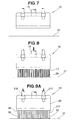
- the horizontally-elongated nozzle plate 16 has a great number of the discharge ports 17 arranged in two rows.
- One of the two rows of the discharge ports 17 is horizontally displaced relative to the other row by one half of a pitch between adjacent discharge ports 17.
- the discharge ports 17 in the two rows are arranged in a staggered fashion.
- a front jet port 31F for emitting a jet of compressed pair.
- a rear jet port 31R for emitting a jet of compressed air.
- the nozzle plate 16 has a length L of 120 mm and a width D of 35 mm.
- the number of the discharge ports 17 defined in the nozzle plate 16 is determined by a width of an area to be coated with the protective coating. For example, where such a width is 90 mm, fifteen discharge ports 17 each having a diameter from 0.4 to 0.6 mm are arranged in a row at pitches of 6 mm while fourteen discharge ports 17 each having a diameter from 0.4 to 0.6 mm are arranged in a row at pitches of 6 mm. Namely, a total of twenty nine discharge ports 17 is provided in a staggered fashion.
- thirty two discharge ports 17 each having a diameter from 0.4 to 0.6 mm may be arranged in a row at pitches of 3 mm while thirty one discharge ports 17 each having a diameter from 0.4 to 0.6 mm may be arranged in a row at pitches of 3 mm.
- a total of sixty three discharge ports 17 is provided in a staggered fashion.
- the nozzle plate 16 may have only one row of fifteen discharge ports 17 arranged at pitches of 6 mm.
- a width of an area to be coated with a protective coating is 48 mm
- eight discharge ports 17 each having a diameter from 0.4 to 0.6 mm are arranged in a row at pitches of 6 mm while seven discharge ports 17 each having a diameter from 0.4 to 0.6 mm are arranged in a row at pitches of 6 mm.
- a total of fifteen discharge ports 17 is arranged in a staggered fashion.
- sixteen discharge ports 17 each having a diameter from 0.4 to 0.6 mm may be arranged in a row at pitches of 3 mm while fifteen discharge ports 17 each having a diameter from 0.4 to 0.6 mm may be arranged in a row at pitches of 3 mm.
- a total of thirty one discharge ports 17 is arranged in a staggered fashion.
- the nozzle plate 16 may have only one row of eight discharge ports 17 arranged at pitches of 6 mm.
- the front and rear plates 20, 20 are disposed on front and rear sides of the block 11. By loosening the fasteners 23, 23, it becomes possible to move the plates 20, 20 vertically a distance equal to or less than a length of the elongated hole 27.
- a main air tube 33 extending from a source 32 of compressed air has a distal end connected to a directional control valve 35 from which two air tubes (front and rear air tubes) 34F, 34R extend.
- the front air tube 34F is connected to the front supply tubes 21F, 21F.
- the rear air tube 34R is connected to the rear supply tubes 21R, 21R.
- the directional control valve 35 is operated by a valve control section 36.
- the valve control section 36 receives a signal A indicative of information on a direction of movement of the application nozzle unit 10.
- the application nozzle unit 10 is disposed facing toward a painted workpiece 37.
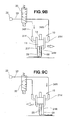
- the operation of the application nozzle unit 10 starts from a step of feeding a protective coating 38 to the workpiece 37. More specifically, as shown in Fig. 8 , the protective coating 38 is discharged out through the discharge ports 17onto the workpiece 37. While discharging the protective coating 38, the application nozzle unit 10 moves in a direction directed down out of a plane of Fig. 8 .
- the operation of the application nozzle unit 10 proceeds to a step of leveling the protective coating 38 on the workpiece 37. More specifically, as shown in Fig. 9A , the protective coating 38 is spread under pressure of compressed air 39 jetting from the jet port 31F.
- the application nozzle unit 10 includes the front and rear jet ports 31F, 31R located forwardly and rearwardly of the discharge ports 17 ( Fig. 1 ), respectively.
- the directional control valve 35 is operated such that compressed air is supplied through the front air tube 34F to the front supply tubes 21F, 21F. Then, the compressed air, designated at 39, jets from the front jet port 31F.
- the directional control valve 35 When the application nozzle unit 10 moves forward (leftward of Fig. 9C ), as shown by a profiled arrow of Fig. 9C , the directional control valve 35 is operated such that compressed air is supplied through the rear air tube 34R to the rear supply tubes 21R, 21R. Then the compressed air, denoted by reference numeral 39, jets from the rear jet port 31R.
- the directional control valve 35 is operated such that the compressed air jets from the corresponding one of the front jet port 31F and the rear jet port 31R. Because the application nozzle unit 10 moves reciprocally without having to make any turn, an applying operation can be more efficiently performed imposing a reduced burden on a robot.
- the protective coating 38 immediately after applied to the workpiece 37, is in the form of a wet film having a thickness of 120 ⁇ m to 200 ⁇ m, preferably, 160 ⁇ m.
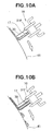
- Discussion will be made as to a case where a diameter of the discharge port 17 is set to be equal to or less than 1 mm, and a case where a diameter of the discharge port 17 is set to exceed 1 mm.
- the discharge ports 17 each having a diameter of 1 mm or less, preferably, in the range of 0.4 to 0.6 mm, discharge jets of the protective coating to a steep surface 41 of a workpiece (not designated).
- the protective coating is put in the form of a thin line on the steep surface 41. This protective coating is rapidly spread over the surface 41 under pressure of compressed air 39 jetting from the front jet port 31F.
- the discharge ports 17 each having a diameter exceeding 1 mm, discharge jets of the protective coating to a steep surface 41 of a workpiece (not designated).
- the protective coating is put in the form of a thick line on the surface 41.
- This protective coating can not be sufficiently spread over the surface 41 under pressure of compressed air 39 jetting from the front jet port 31F.
- parts of the protective coating descend in the form of drops along the surface 41.
- the diameter of the discharge port 17 is 1 mm or less, preferably, in the range of 0.4 to 0.6 mm.
- the discharge ports 17 is not only circular but also square, rectangular or octagonal in shape.
- the discharge ports 17 are designed to be small in size on the basis of viscosity and thixotropy of the protective coating.
- the thixotropy means a property of varying in viscosity when the coating is subjected to a shearing force.
- a plate 20B is made of a rectangular plate 26 having on one side surface a plurality of groove portions 42 of V-shaped cross-sections, in place of the shallow recessed portion 29 shown in Fig. 4 .
- the groove portions 42 have their individually set depths. Namely, the depth of the groove portion 42 is easier to set than that of the recessed portion 29.
- the present invention is also applicable to protection of paint films formed on vehicle bodies, machines and the like.
- the application method and nozzle unit of the present invention are useful in applying a protective coating to a painted vehicle body.
Landscapes
- Coating Apparatus (AREA)
- Spray Control Apparatus (AREA)
- Application Of Or Painting With Fluid Materials (AREA)
Abstract
Claims (3)
- Procédé pour appliquer un revêtement protecteur (38) à une pièce de fabrication (32) peinte, le procédé comprenant les étapes consistant à :distribuer le revêtement protecteur (38) à partir d'une unité de buse d'application (10) sur la pièce de fabrication (37), l'unité de buse d'application (10) comportant une pluralité d'orifices de décharge (17), un orifice de jet avant (31F) situé en avant des orifices de décharge (17), et un orifice de jet arrière (31R) situé à l'arrière des orifices de décharge (17) ; etrayonner des jets d'air comprimé (39) vers le revêtement protecteur (38) délivré pour, de ce fait, étaler uniformément le revêtement protecteur (38), dans lequel l'étape de distribution comprend la décharge avec les jets d'air comprimé (39) du revêtement protecteur (38) à partir des orifices de décharge (17) de l'unité de buse d'application (10) tout en déplaçant l'unité de buse d'application (10) en avant et arrière, et l'étape de rayonnement comprend la projection des jets d'air comprimé (39) uniquement à partir de l'orifice de jet avant (31F) de l'unité de buse d'application (10) pendant le mouvement vers l'arrière de l'unité de buse d'application (10), et la projection des jets d'air comprimé uniquement à partir de l'orifice de jet arrière (31R) de l'unité de buse d'application (10) pendant le mouvement vers l'avant de l'unité de buse d'application (10).
- Dispositif d'application pour appliquer un revêtement protecteur (38) à une pièce de fabrication (37) peinte, le dispositif comprenant :une unité de buse d'application (10) mobile ;une vanne de commande directionnelle (35) ;l'unité de buse d'application (10) comprenant :un bloc (11) comportant un réservoir de revêtement (12) défini dans celui-ci pour contenir le revêtement protecteur (38) ;une plaque de buse (16) comportant une pluralité d'orifices de décharge (17) définis dans celle-ci pour décharger le revêtement protecteur (38) de l'intérieur du réservoir de revêtement (12) ;un tube de distribution (14), prévu sur une surface supérieure du bloc (11), pour distribuer le revêtement protecteur (38) dans le réservoir de revêtement (12) ;des plaques avant et arrière (20, 20B) prévues sur les surfaces avant et arrière du bloc (11) , respectivement, les plaques avant et arrière (20, 20B) comportant chacune au moins une partie découpée ;une paire de tubes d'alimentation (21F, 21R), prévus sur les plaques avant et arrière (20, 20B), respectivement, pour délivrer de l'air comprimé dans les espaces entre la plaque avant (20) et la surface avant du bloc (11) et entre la plaque arrière (20) et la surface arrière du bloc (11) ;une paire d'orifices de jet avant et arrière (31F, 31F), définis entre la plaque de buse (16) et une partie inférieure de la plaque avant (20, 20B) et entre la plaque de buse (16) et une partie inférieure de la plaque arrière (20, 20B), respectivement, pour émettre des jets d'air comprimé (39) pour étaler le revêtement protecteur (38) déchargé des orifices de décharge (17) ; etla vanne de commande directionnelle (35) permettant l'alimentation en air comprimé (39) de l'un de la paire de tubes d'alimentation (21F, 21R) sur la base d'une direction de mouvement de l'unité de buse d'application (10),dans lequel ladite au moins une partie découpée comprend une pluralité de parties formant rainures (42) avec une section transversale en forme de V.
- Dispositif d'application selon la revendication 2, dans lequel les plaques avant et arrière (20, 20B) peuvent être déplacées verticalement par rapport au bloc (11).
Applications Claiming Priority (2)
| Application Number | Priority Date | Filing Date | Title |
|---|---|---|---|
| JP2005162553A JP2006334512A (ja) | 2005-06-02 | 2005-06-02 | 塗膜保護材塗布方法及び同塗布ノズル |
| PCT/JP2006/311046 WO2006129776A1 (fr) | 2005-06-02 | 2006-05-26 | Systeme d’application d’un revetement protecteur |
Publications (2)
| Publication Number | Publication Date |
|---|---|
| EP1901854A1 EP1901854A1 (fr) | 2008-03-26 |
| EP1901854B1 true EP1901854B1 (fr) | 2009-07-15 |
Family
ID=36677100
Family Applications (1)
| Application Number | Title | Priority Date | Filing Date |
|---|---|---|---|
| EP06766431A Ceased EP1901854B1 (fr) | 2005-06-02 | 2006-05-26 | Systeme d'application d'un revetement protecteur |
Country Status (8)
| Country | Link |
|---|---|
| US (1) | US20090304936A1 (fr) |
| EP (1) | EP1901854B1 (fr) |
| JP (1) | JP2006334512A (fr) |
| CN (1) | CN101237944A (fr) |
| BR (1) | BRPI0610913A2 (fr) |
| CA (1) | CA2609962A1 (fr) |
| DE (1) | DE602006007849D1 (fr) |
| WO (1) | WO2006129776A1 (fr) |
Families Citing this family (18)
| Publication number | Priority date | Publication date | Assignee | Title |
|---|---|---|---|---|
| JP4185084B2 (ja) * | 2005-09-26 | 2008-11-19 | 本田技研工業株式会社 | 水性塗料の塗布方法及び同塗布ノズル |
| DE102007034877A1 (de) * | 2007-07-24 | 2009-01-29 | Schmid Rhyner Ag | Verfahren und Vorrichtung zum Auftrag von Kunststoffbeschichtungen |
| JP2012139682A (ja) * | 2012-01-23 | 2012-07-26 | Dainippon Printing Co Ltd | 塗工装置、及び塗工方法 |
| JP6119657B2 (ja) * | 2014-04-02 | 2017-04-26 | トヨタ車体株式会社 | 塗装方法 |
| US10000049B2 (en) * | 2014-06-23 | 2018-06-19 | Exel Industries | Methods and apparatus for applying protective films |
| DE102014212940A1 (de) * | 2014-07-03 | 2016-01-07 | Fraunhofer-Gesellschaft zur Förderung der angewandten Forschung e.V. | Modul, System und Verfahren zum Auftragen eines viskosen Mediums auf eine Oberfläche und Verfahren zum Herstellen des Moduls |
| JP6917329B2 (ja) * | 2018-03-22 | 2021-08-11 | 東レエンジニアリング株式会社 | 塗布装置 |
| CN110624778A (zh) * | 2019-10-31 | 2019-12-31 | 桂林海威科技股份有限公司 | 一种用于led显示屏灯板模组的补胶方法及装置和应用 |
| EP4074782B1 (fr) | 2021-04-12 | 2024-03-20 | Axalta Coating Systems GmbH | Procédé d'application d'une composition de revêtement à base de solvant sur un substrat à l'aide d'un applicateur à haut rendement de transfert pour y former une couche de revêtement |
| US12486411B2 (en) | 2021-04-30 | 2025-12-02 | Axalta Coating Systems Ip Co., Llc | Method of applying a one-component waterborne coating composition to a substrate utilizing a high transfer efficiency applicator |
| EP4094847A1 (fr) | 2021-05-27 | 2022-11-30 | Axalta Coating Systems GmbH | Compositions de revêtement et procédés d'application |
| DE112022004222T5 (de) | 2021-08-30 | 2024-06-20 | Axalta Coating Systems Gmbh | Verfahren zum auftragen einer beschichtungszusammensetzung auf ein substrat |
| US12459000B2 (en) | 2021-12-21 | 2025-11-04 | Axalta Coating Systems Ip Co., Llc | Methods of coating a substrate |
| JP2026509455A (ja) | 2023-03-10 | 2026-03-19 | アクサルタ コーティング システムズ ゲゼルシャフト ミット ベシュレンクテル ハフツング | コーティング組成物及び関連方法 |
| JP7392192B1 (ja) | 2023-04-28 | 2023-12-05 | アーベーベー・シュバイツ・アーゲー | 塗装機 |
| KR20260003134A (ko) | 2023-04-28 | 2026-01-06 | 악살타 코팅 시스템즈 게엠베하 | 고 전달 효율 어플리케이터를 이용하여 기판에 코팅 조성물을 도포하는 방법 |
| CN121263312A (zh) | 2023-06-23 | 2026-01-02 | 艾仕得涂料系统有限责任公司 | 涂层施加系统和涂覆基材的方法 |
| US20250084253A1 (en) | 2023-09-11 | 2025-03-13 | Axalta Coating Systems Ip Co., Llc | Coating compositions and formulation methods |
Family Cites Families (5)
| Publication number | Priority date | Publication date | Assignee | Title |
|---|---|---|---|---|
| JPS53118442A (en) * | 1977-03-26 | 1978-10-16 | Konishiroku Photo Ind | Painting method |
| US5800614A (en) * | 1996-09-24 | 1998-09-01 | Foust; Paul William | Adhesive applier for screen printing machine |
| US6156373A (en) * | 1999-05-03 | 2000-12-05 | Scimed Life Systems, Inc. | Medical device coating methods and devices |
| AUPR949801A0 (en) * | 2001-12-14 | 2002-01-24 | Industrial Automation Services Pty Ltd | Process control method and apparatus |
| JP2004148167A (ja) * | 2002-10-29 | 2004-05-27 | Nordson Corp | 粘性流体材料の塗布方法及び装置 |
-
2005
- 2005-06-02 JP JP2005162553A patent/JP2006334512A/ja not_active Withdrawn
-
2006
- 2006-05-26 WO PCT/JP2006/311046 patent/WO2006129776A1/fr not_active Ceased
- 2006-05-26 DE DE602006007849T patent/DE602006007849D1/de not_active Expired - Fee Related
- 2006-05-26 EP EP06766431A patent/EP1901854B1/fr not_active Ceased
- 2006-05-26 BR BRPI0610913-6A patent/BRPI0610913A2/pt not_active IP Right Cessation
- 2006-05-26 CA CA002609962A patent/CA2609962A1/fr not_active Abandoned
- 2006-05-26 US US11/921,543 patent/US20090304936A1/en not_active Abandoned
- 2006-05-26 CN CNA2006800285974A patent/CN101237944A/zh active Pending
Also Published As
| Publication number | Publication date |
|---|---|
| JP2006334512A (ja) | 2006-12-14 |
| CA2609962A1 (fr) | 2006-12-07 |
| BRPI0610913A2 (pt) | 2008-12-02 |
| EP1901854A1 (fr) | 2008-03-26 |
| CN101237944A (zh) | 2008-08-06 |
| US20090304936A1 (en) | 2009-12-10 |
| WO2006129776A1 (fr) | 2006-12-07 |
| DE602006007849D1 (de) | 2009-08-27 |
Similar Documents
| Publication | Publication Date | Title |
|---|---|---|
| EP1901854B1 (fr) | Systeme d'application d'un revetement protecteur | |
| EP2711088B1 (fr) | Buse de pelliculage, dispositif de revêtement et procédé de revêtement | |
| US8499713B2 (en) | Water-based coating application system | |
| JP6335992B2 (ja) | 塗装機器および塗装方法 | |
| US6811807B1 (en) | Method of applying a peel-off protective layer | |
| CN106660069B (zh) | 用于涂覆保护膜的方法和设备 | |
| JPH06154691A (ja) | 電子回路基板に相似なコーテイングの塗布装置と方法 | |
| CA2082264A1 (fr) | Imprimante a jet d'encre goutte a la demande et procede de fabrication de celle-ci | |
| US5976249A (en) | Varnishing head | |
| US20040217202A1 (en) | Airless conformal coating apparatus and method | |
| US5686145A (en) | Method of forming a protective film on a coated surface and apparatus for carrying out the same | |
| US20060102213A1 (en) | Nozzle arrangement | |
| CN101674895A (zh) | 用于在涂敷面上涂敷液态涂料的方法及装置 | |
| EP1205308A3 (fr) | Procédé de correction pour imprimante à jet d'encre continu | |
| CZ20012015A3 (cs) | Zařízení a způsob rozpraąovacího vytlačování | |
| CN210995058U (zh) | 一种刮涂机构及极片刮涂机 | |
| JPH06121944A (ja) | 塗装装置 | |
| JP3478523B2 (ja) | 厚塗り用噴射ノズル装置および塗装方法並びに自動車ボデイ | |
| JP2831288B2 (ja) | 自動車の塗装表面へストリッパブルペイントを塗布する装置 | |
| JPH10216599A5 (fr) | ||
| JP2005000887A (ja) | 塗工方法及び塗工装置 | |
| JP6871429B2 (ja) | 塗装装置 | |
| JPH08173897A (ja) | 塗装面の保護膜形成方法 | |
| JP4358657B2 (ja) | リップコータ型塗工装置 | |
| TWI710456B (zh) | 一種漸層式面光源之製造裝置 |
Legal Events
| Date | Code | Title | Description |
|---|---|---|---|
| PUAI | Public reference made under article 153(3) epc to a published international application that has entered the european phase |
Free format text: ORIGINAL CODE: 0009012 |
|
| 17P | Request for examination filed |
Effective date: 20080102 |
|
| AK | Designated contracting states |
Kind code of ref document: A1 Designated state(s): DE GB |
|
| RIN1 | Information on inventor provided before grant (corrected) |
Inventor name: NAKAZAWA, YOSHIYUKI,C/O HONDA MOTOR CO., LTD. |
|
| DAX | Request for extension of the european patent (deleted) | ||
| RBV | Designated contracting states (corrected) |
Designated state(s): DE GB |
|
| 17Q | First examination report despatched |
Effective date: 20080911 |
|
| GRAP | Despatch of communication of intention to grant a patent |
Free format text: ORIGINAL CODE: EPIDOSNIGR1 |
|
| GRAS | Grant fee paid |
Free format text: ORIGINAL CODE: EPIDOSNIGR3 |
|
| GRAA | (expected) grant |
Free format text: ORIGINAL CODE: 0009210 |
|
| AK | Designated contracting states |
Kind code of ref document: B1 Designated state(s): DE GB |
|
| REG | Reference to a national code |
Ref country code: GB Ref legal event code: FG4D |
|
| REF | Corresponds to: |
Ref document number: 602006007849 Country of ref document: DE Date of ref document: 20090827 Kind code of ref document: P |
|
| PLBE | No opposition filed within time limit |
Free format text: ORIGINAL CODE: 0009261 |
|
| STAA | Information on the status of an ep patent application or granted ep patent |
Free format text: STATUS: NO OPPOSITION FILED WITHIN TIME LIMIT |
|
| 26N | No opposition filed |
Effective date: 20100416 |
|
| GBPC | Gb: european patent ceased through non-payment of renewal fee |
Effective date: 20100526 |
|
| PG25 | Lapsed in a contracting state [announced via postgrant information from national office to epo] |
Ref country code: DE Free format text: LAPSE BECAUSE OF NON-PAYMENT OF DUE FEES Effective date: 20101201 |
|
| PG25 | Lapsed in a contracting state [announced via postgrant information from national office to epo] |
Ref country code: GB Free format text: LAPSE BECAUSE OF NON-PAYMENT OF DUE FEES Effective date: 20100526 |