EP1902192B1 - Procede et dispositif de fixation d'une unite entrainement a engrenage a une partie de la carrosserie d'un vehicule a moteur - Google Patents
Procede et dispositif de fixation d'une unite entrainement a engrenage a une partie de la carrosserie d'un vehicule a moteur Download PDFInfo
- Publication number
- EP1902192B1 EP1902192B1 EP06755228.1A EP06755228A EP1902192B1 EP 1902192 B1 EP1902192 B1 EP 1902192B1 EP 06755228 A EP06755228 A EP 06755228A EP 1902192 B1 EP1902192 B1 EP 1902192B1
- Authority
- EP
- European Patent Office
- Prior art keywords
- drive unit
- gearbox drive
- bodywork part
- radial webs
- bayonet
- Prior art date
- Legal status (The legal status is an assumption and is not a legal conclusion. Google has not performed a legal analysis and makes no representation as to the accuracy of the status listed.)
- Ceased
Links
- 238000000034 method Methods 0.000 title claims description 15
- 230000033001 locomotion Effects 0.000 claims description 9
- 238000001746 injection moulding Methods 0.000 claims 1
- 230000000630 rising effect Effects 0.000 claims 1
- 230000005540 biological transmission Effects 0.000 description 33
- 230000015572 biosynthetic process Effects 0.000 description 2
- 238000011161 development Methods 0.000 description 2
- 230000018109 developmental process Effects 0.000 description 2
- 238000005755 formation reaction Methods 0.000 description 2
- 238000002347 injection Methods 0.000 description 2
- 239000007924 injection Substances 0.000 description 2
- 239000002184 metal Substances 0.000 description 2
- 239000000243 solution Substances 0.000 description 2
- 206010053648 Vascular occlusion Diseases 0.000 description 1
- 238000005452 bending Methods 0.000 description 1
- 230000001419 dependent effect Effects 0.000 description 1
- 230000002349 favourable effect Effects 0.000 description 1
- 238000004519 manufacturing process Methods 0.000 description 1
- 239000000463 material Substances 0.000 description 1
- 210000003739 neck Anatomy 0.000 description 1
Images

Classifications
-
- H—ELECTRICITY
- H02—GENERATION; CONVERSION OR DISTRIBUTION OF ELECTRIC POWER
- H02K—DYNAMO-ELECTRIC MACHINES
- H02K5/00—Casings; Enclosures; Supports
-
- E—FIXED CONSTRUCTIONS
- E05—LOCKS; KEYS; WINDOW OR DOOR FITTINGS; SAFES
- E05F—DEVICES FOR MOVING WINGS INTO OPEN OR CLOSED POSITION; CHECKS FOR WINGS; WING FITTINGS NOT OTHERWISE PROVIDED FOR, CONCERNED WITH THE FUNCTIONING OF THE WING
- E05F15/00—Power-operated mechanisms for wings
- E05F15/60—Power-operated mechanisms for wings using electrical actuators
- E05F15/603—Power-operated mechanisms for wings using electrical actuators using rotary electromotors
- E05F15/665—Power-operated mechanisms for wings using electrical actuators using rotary electromotors for vertically-sliding wings
- E05F15/689—Power-operated mechanisms for wings using electrical actuators using rotary electromotors for vertically-sliding wings specially adapted for vehicle windows
- E05F15/697—Motor units therefor, e.g. geared motors
-
- E—FIXED CONSTRUCTIONS
- E05—LOCKS; KEYS; WINDOW OR DOOR FITTINGS; SAFES
- E05Y—INDEXING SCHEME ASSOCIATED WITH SUBCLASSES E05D AND E05F, RELATING TO CONSTRUCTION ELEMENTS, ELECTRIC CONTROL, POWER SUPPLY, POWER SIGNAL OR TRANSMISSION, USER INTERFACES, MOUNTING OR COUPLING, DETAILS, ACCESSORIES, AUXILIARY OPERATIONS NOT OTHERWISE PROVIDED FOR, APPLICATION THEREOF
- E05Y2900/00—Application of doors, windows, wings or fittings thereof
- E05Y2900/50—Application of doors, windows, wings or fittings thereof for vehicles
- E05Y2900/53—Type of wing
- E05Y2900/55—Windows
-
- H—ELECTRICITY
- H02—GENERATION; CONVERSION OR DISTRIBUTION OF ELECTRIC POWER
- H02K—DYNAMO-ELECTRIC MACHINES
- H02K7/00—Arrangements for handling mechanical energy structurally associated with dynamo-electric machines, e.g. structural association with mechanical driving motors or auxiliary dynamo-electric machines
- H02K7/10—Structural association with clutches, brakes, gears, pulleys or mechanical starters
- H02K7/116—Structural association with clutches, brakes, gears, pulleys or mechanical starters with gears
- H02K7/1163—Structural association with clutches, brakes, gears, pulleys or mechanical starters with gears where at least two gears have non-parallel axes without having orbital motion
- H02K7/1166—Structural association with clutches, brakes, gears, pulleys or mechanical starters with gears where at least two gears have non-parallel axes without having orbital motion comprising worm and worm-wheel
-
- H—ELECTRICITY
- H02—GENERATION; CONVERSION OR DISTRIBUTION OF ELECTRIC POWER
- H02K—DYNAMO-ELECTRIC MACHINES
- H02K7/00—Arrangements for handling mechanical energy structurally associated with dynamo-electric machines, e.g. structural association with mechanical driving motors or auxiliary dynamo-electric machines
- H02K7/14—Structural association with mechanical loads, e.g. with hand-held machine tools or fans
Definitions
- the invention relates to a device, and a method for connecting a transmission drive unit with a body part of a motor vehicle according to the preamble of the independent claims.
- a transmission drive unit for adjusting moving parts in the motor vehicle which is fastened by means of Anschraubdomen on a body part.
- the mounting domes are slidably mounted on the gear drive unit so that the bolt-on points of the gear drive unit can be varied according to the custom body part without modifying the housing of the power unit.
- attachment of the gear drive unit is relatively variable, but when mounting the Anschraubdome must be positioned in the correct manner.
- the screwing or riveting, as well as the provision of these connecting means is a relatively expensive process step.
- the FR-A-2863323 also shows an adjustment drive which is attached to a fixed component.
- a cover of a transmission housing is closed positively by means of a rotational movement relative to the fixed component.
- the inventive device and the inventive method for connecting a transmission drive unit with a body part with the features of the independent claims have the advantage that by the connection of the transmission drive unit can be dispensed with the body part by means of a bayonet-type mounting geometry, completely on the mounting screws and the Anschraub mixes. This significantly reduces the cycle time and the variety of parts during assembly. By the formation of radial webs on both the body part, and on the transmission drive unit, the latter can be attached by a simple rotational movement of the bayonet lock very quickly and without additional tools on the body.
- the radial webs of the gear drive unit axially engage between the radial webs of the body part in such a way that the radial webs slide over one another in the circumferential direction by a simple rotation of the gear drive unit, whereby a reliable, axial fixation is ensured .
- the connection between the body part and the drive unit is secured by means of a twist lock.
- the twist lock is automatically activated during assembly of the drive unit and can be solved for targeted disassembly of the transmission drive unit again.
- a gear drive unit proves to be advantageous in which the radial webs are formed directly on the gear housing of the drive unit.
- These can for example be made in one piece with the gear housing as an injection molded part made of plastic.
- the radial webs are formed with respect to the closing direction of the bayonet closure such that the sliding over of the bayonet elements by a molded-on phase or inclined surface is simplified. As a result, practically the "threading" of the radial webs when closing the bayonet closure is facilitated.
- the phases can also be formed on the separate fastening ring of the bayonet closure.
- the radial webs of the drive unit and the body part are axially against each other, wherein the axial connection is achieved for an additional mounting ring, which also has bayonet-like, radial mounting tabs which are pushed in the circumferential direction over the radial webs in the manner of a bayonet closure become.
- the transmission drive unit does not need to be rotated relative to the body part, but only the mounting ring. This has the advantage that in a self-locking drive unit, the body-side adjustment mechanism does not have to be set in motion during assembly of the transmission drive unit.
- the rotation lock prevents unwanted rotation of the drive unit by an axial positive engagement between the body part and the transmission drive unit, in which a holding element engages axially in a corresponding counter-element.
- Such locking or clip elements can be easily disassembled for disassembly of the drive unit due to the easily accessible arrangement radially outside the climbs.
- a rotation lock gear drive units can be attached to the body in a particularly advantageous manner, which operate in forward and reverse operation, as is the case for example with window regulators, sunroofs or seat adjusters. Due to the constant torque change, it is particularly important here that the rotary locking reliably prevents loosening of the bayonet lock in the direction of rotation. If a separate mounting ring of the bayonet lock is used, so that self-locking drive units can be easily mounted without much effort.
- connection device for the connection of a sunroof drive to a roof frame of the motor vehicle.
- the driven element designed as a driven pinion can directly axially into the riser of the sunroof mechanism be inserted and fixed reliably by a simple rotation of the bayonet lock. As a result, the assembly time and thus the manufacturing cost is significantly reduced.
- the body part is designed as a fastening flange, the advantageous bayonet closure on the drive unit can already be realized, even if the customer's connection point of the body does not yet have any bayonet elements.
- this design not only serves as a temporary solution, but the mounting flange can also serve as an adapter element for any body-side customer interfaces, where always the identical drive unit can be used.
- a body part where the radial webs are also formed directly.
- This can be formed, for example, as a stamped sheet metal part, or as a plastic injection molded part.
- the inventive method for connecting a transmission drive unit with a body part allows a particularly time-saving and thus cost-effective assembly method, since the bayonet lock can be closed by a simple rotation and reliably secured against detachment.
- the two components with the radial webs are pushed axially into one another, so that the output element coupled with the adjustment and by the subsequent rotation of the transmission drive unit on the one hand, the radial webs of the two components are pushed one behind the other and simultaneously locks the twist lock.
- Such an extremely simple assembly process is a great advantage for the customer, who can purchase a completely assembled transmission drive unit and easily attach it to his custom body part.
- a transmission drive unit 12 which has an electric motor 14, an electronics housing 16 and a transmission housing 18.
- the electric motor 14 has an armature shaft 20, not shown, with a worm 22, which is provided with a in the Gear housing 18 mounted worm wheel 24 meshes.
- the worm wheel 24 is mounted together with an output element 26 on an output shaft 28.
- the output shaft 28 protrudes through a guide dome 30 from the transmission housing 18, so that as output element 26, a driven pinion 27 is mounted by means of a locking ring 32 outside of the transmission housing 18 on the output shaft 28.
- radial webs 34 are arranged on the gear drive unit 12, each extending over an angular range 38 in the circumferential direction 36 of about 60 °.
- the radial webs 34 are connected via an axial sleeve 40 with the gear housing 18, this sleeve 40 may be formed in an alternative embodiment, however, also as ring segments.
- the radial webs 34 are formed directly on the guide dome 30.
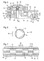
- a transmission drive unit 12 is connected to a body part 11, which is designed as a roof frame 52 of a motor vehicle.
- a mechanism 54 is mounted, with a movable part in the vehicle, such as a sliding roof, can be adjusted.
- the adjustment mechanism 54 is formed by two risers 56, which are connected to the part to be adjusted (sliding roof).
- the output element 26 engages in the adjustment mechanism 54 and is connected by means of a bayonet lock 58 fixed to the body part 11.
- the body part 11 has - as the gear drive unit 12 - also bayonet-like, radial webs 34 which engage in the connected state in the manner of the bayonet lock 58 into one another.
- the radial webs 34 of the drive unit 12 extend radially outward from the axial extension 35, while the radial webs 34 of the body part 11 extend radially inwardly with respect to their axial extensions 35. This makes it possible for the respective radial webs 34 to engage in one another, which fix the drive unit 12 axially with respect to the body part 11 when the bayonet connection 58 is closed at the time of rotation.
- the radial webs 34 each have a phase 64 and inclined surfaces 65, so that the radial webs can be easily pushed one behind the other in the circumferential direction 36 when closing the bayonet closure 58.
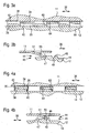
- FIG. 3b shows the twist lock 44 in the so-called mounting position, in which the retaining element 50 is not yet engaged in the counter-element 46.
- the locking element 51 which is arranged radially outside of the radial webs 34, in a simple manner in the illustration according to FIG. 4b are pushed upward, whereby a rotation for releasing the bayonet connection 58 is made possible.
- FIG. 5 shows an alternative embodiment of the connecting device 10 according to the invention, in which, as in FIG. 2 the transmission drive unit 12 engages again via the output element 26 in the adjustment mechanism 54 of the body part 11.
- the radial webs 34 of the two components 12, 11 are axially against each other, without these mutually engage one behind the other.
- This assembly position is as a development schematic in FIG. 7 represented, in each case over the entire periphery 36 in each case 3 radial webs 34 are formed, which are arranged congruently in the mounting position.
- the axial fixation of the two components 12 and 11 is carried out in this embodiment by means of an additional fastening ring 68 which in FIG. 6 is shown.
- the fastening ring 68 has a closed circumference 70, on each of which radial attachment straps 72 are integrally formed on both end faces, which are formed as angle segments 38, between which approximately equal-sized recesses 74 are formed in the circumferential direction 36.
- FIG. 7 is a section through the radial webs 34 and the mounting ring 68 shown in the assembled position, in which the radial fastening tabs 72 with respect to the circumferential direction 36 between the congruent radial webs 34 of the components 12 and 11 are arranged.
- the fastening ring 68 can be pushed in the axial direction 60 over the radial webs 34, so that the radial webs 34 of the two components 12, 11 are arranged axially between the fastening tabs 72.
- the holding element 50 is simultaneously inserted in the axial direction 60 in the counter-element 46 of the rotary lock 44.
- an axial positive locking 45 is provided, which prevents rotation of the drive unit 12 relative to the body part 11.
- the fastening ring 68 is now rotated in the circumferential direction 36 in a further assembly step, so that the fastening tabs 72 overlap with the radial webs 34 in the circumferential direction 36.
- the drive unit 12 is also reliably secured against rotation on the body part 11, as in the locking position in FIG. 5 is shown.
- the mounting flanges 72 together with the closed periphery 70 of the mounting ring 68 U-shaped brackets 76 which comprise the radial webs 34 of the two components 11, 12 in the axial direction 60 (see left side of FIG. 5 ).
- the radial attachment tabs 72 of the mounting ring 68 take over the function of the radial webs 34 of the Body part 11 off FIG. 2 because the fastening tabs 72 also extend radially inwardly.
- the transmission drive unit 12 can be connected in a very simple manner to the body part 11 without having to rotate the transmission drive unit 12.
- the drive unit 12 is inserted axially in the assembly position in the body part 11 and at the same time created an axial positive locking 45 as a rotation lock 44.
- the preassembled mounting ring 68 is rotated relative to the two components 11 and 12 in the circumferential direction 36 and thereby fixes the two components 11 and 12 axially against each other.
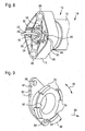
- FIG. 8 is another example of a connecting device 10 is shown, in which the drive unit 12 is connected by means of a bayonet lock 58 with the body part 11, which is designed here as a mounting flange 80.
- the mounting flange 80 has a central opening 82, on the circumference of the radial webs 34 are formed, which engage after pushing in the axial direction 60 and a rotational movement in the circumferential direction 36 behind the radial webs 34 of the drive unit 12.
- the radial webs 34 of the drive unit 12 are in FIG. 8 not visible and are here directly on the electric motor 14, in particular integrally formed with a pole housing 15 as radial recesses or radial extensions made of metal.
- a pin 84 is inserted as a retaining element 50 axially through a hole 85 of the mounting flange 80 in a form-fitting manner in the counter element 46 in the drive unit.
- the counter element 46 is formed as an axial recess 48, wherein the holding element 50 is inserted here only after the rotational movement for closing the bayonet lock 58 to form an axial positive locking 45 which locks the bayonet lock 58.
- the mounting flange 80 has receptacles 86 for separate connection means, with which the mounting flange 80 can be attached as a body part 11 to a further body part 11.
- Such a mounting flange 80 with bayonet lock 58 is particularly useful when the interface of the drive unit 12 has already been switched to a fastener-free bayonet lock 58, the custom body-side interface is still equipped with screw-on points. Therefore, such a mounting flange 58 is an interim solution, or an adapter 80 for different body connections.
- the output element 26 is formed as a flex shaft 25 which engages positively in the output shaft 28 within the housing 15, 18.
- the transmission is the transmission drive unit 12 arranged for example on the body part 11 or on the moving part to be adjusted.
- FIG. 9 shows a further body part 11, which is designed as a mounting flange 80.
- This in turn has receptacles 86 for connecting means for attachment to a further body part 11 and provides an alternative embodiment to the mounting flange 80 in FIG. 8
- the mounting flange 80 is formed as a one-piece bending stamped part 81 and has radial webs 34, which are connected via axial extensions 35 with the mounting flange 80. Centered within the webs 34, the opening 82 is again arranged, in which an output element 26 and / or a guide dome 30 of the gear drive unit 12 is engageable.
- the mounting flange is bayonet-like first pushed axially, the radial webs 34 of the mounting flange 80 tooth-like between the radial webs 34 of the drive unit 12 engage and then rotated so that the radial webs 34 are pushed one behind the other.
- a lock 44 of the bayonet lock 58 material of the mounting flange 80 is plastically deformed in this case, and pressed, for example, in corresponding formed as counter-elements 50 formations.
- the radial webs 34 of the mounting flange 80 are plastically deformed after closing the bayonet lock 58 against counter-elements 50 on the drive unit 80, whereby an axial positive locking 45 or a non-positive locking 44 is generated.
- the number and the specific embodiment of the radial webs 34 and the fastening tabs 72 and their connection to the components 12 and 11 can be varied as desired.
- two or four radial webs 34 and / or fastening straps 72 may be formed, whereby the angular range 38 of the individual webs or the intermediate spaces between them may vary and the angular range of the webs 34 and the intermediate spaces need not be equal.
- the rotational lock 44 with the retaining element 50 and counter element 46 and their arrangement on the two components 11 and 12 can be modified.
- the drive unit 12 is preferably fastened directly to a body part 11 without any further connection means, but can also be attached by means of a bayonet lock 58 to a body part designed as a fastening flange 80 11 are connected, which in turn is attached in any way to the body.
- the device 10 according to the invention and the method according to the invention for the attachment of a sunroof drive to the roof frame is used, but can also be used for other adjusting drives in the motor vehicle, for example for Wegverstellvorraumen.
Landscapes
- Engineering & Computer Science (AREA)
- Power Engineering (AREA)
- Gear Transmission (AREA)
Claims (11)
- Dispositif (10) pour relier une unité d'entraînement de transmission (12) pour un lève-vitre ou un toit coulissant à une partie de carrosserie (11) d'un véhicule automobile, l'unité d'entraînement de transmission (12) comprenant un moteur électrique (14) qui est accouplé à un élément de sortie (26) disposé sur un arbre de sortie (28), et l'élément de sortie (26) pouvant être mis en prise dans un mécanisme (54) fixé à la partie de carrosserie (11), afin de régler une partie mobile du véhicule automobile, des nervures radiales (34) de type baïonnette étant formées tant sur la partie de carrosserie (11) que sur l'unité d'entraînement de transmission (12), au moyen desquelles nervures l'unité d'entraînement de transmission (12) peut être fixée à la partie de carrosserie (11) à la manière d'une fermeture à baïonnette (58), caractérisé en ce que les nervures radiales (34) sont formées d'un seul tenant sur un boîtier de transmission (18) de l'unité d'entraînement de transmission (12), et l'unité d'entraînement de transmission (12) peut être fixée axialement par une rotation de celle-ci par rapport à la partie de carrosserie (11), un verrouillage en rotation (44) étant disposé entre l'unité d'entraînement de transmission (12) et la partie de carrosserie (11), lequel verrouillage en rotation empêche une libération indésirable de la fermeture à baïonnette fermée (58), et le verrouillage en rotation (44, 45) étant réalisé sous forme d'élément d'encliquetage (50, 51) qui s'encliquète dans un élément d'encliquetage conjugué (46, 48) correspondant lors de la rotation lors de la fermeture de la fermeture à baïonnette (58).
- Dispositif (10) selon la revendication 1, caractérisé en ce que les nervures radiales (34) sont disposées de manière concentrique à l'arbre de sortie (28) et s'étendent sur une zone angulaire (38) dans la direction périphérique (36), laquelle zone angulaire vaut au maximum 90°.
- Dispositif (10) selon la revendication 1 ou 2, caractérisé en ce que les nervures radiales (34) présentent dans la direction périphérique (36) un chanfrein (64) ou une surface chanfreinée (65), afin de faciliter un mouvement de rotation lors de la fermeture de la fermeture à baïonnette (58).
- Dispositif (10) selon l'une quelconque des revendications précédentes, caractérisé en ce que l'unité d'entraînement de transmission (12) est réalisée sous forme d'entraînement de toit coulissant et l'élément de sortie (26) vient en prise, à l'état monté, dans au moins un câble hélicoïdal (56) monté dans la partie de carrosserie (11), la partie de carrosserie (11) étant réalisée sous forme de cadre de toit (52) d'un toit coulissant.
- Dispositif (10) selon l'une quelconque des revendications précédentes, caractérisé en ce que la fermeture à baïonnette (58) comprend une bague de fixation (68) supplémentaire pourvue de pattes de fixation radiales (72), laquelle bague de fixation peut être entraînée en rotation pour la fixation axiale de l'unité d'entraînement de transmission (12) sur la partie de carrosserie (11) par rapport aux nervures radiales (34).
- Dispositif (10) selon l'une quelconque des revendications précédentes, caractérisé en ce que le verrouillage en rotation (44, 45) est disposé radialement à l'extérieur des nervures radiales (34) et est réalisé sous forme d'élément de retenue (50) qui vient en prise par complémentarité de formes, en particulier dans la direction axiale (60), dans un élément conjugué (46, 48) correspondant.
- Dispositif (10) selon l'une quelconque des revendications précédentes, caractérisé en ce que l'élément de sortie (26) peut transmettre un moment de sortie dans les deux sens de rotation (36), et l'élément de sortie (26) est réalisé de manière autobloquante par rapport au moteur électrique (14).
- Unité d'entraînement de transmission (12) comprenant un boîtier de transmission (18) pour l'utilisation dans un dispositif (10) selon l'une quelconque des revendications précédentes, caractérisée en ce que les nervures radiales (34) sont fabriquées par moulage par injection de plastique.
- Partie de carrosserie (11) comprenant un mécanisme de réglage (54) disposé sur celle-ci pour l'utilisation dans un dispositif (10) selon l'une quelconque des revendications précédentes, caractérisée en ce que les nervures radiales (34) sont formées sur la partie de carrosserie (11) et sont en particulier fabriquées d'un seul tenant avec celle-ci.
- Procédé pour relier une unité d'entraînement de transmission (12) pour un lève-vitre ou un toit coulissant à une partie de carrosserie (11) selon l'une quelconque des revendications précédentes, caractérisé par les étapes suivantes :- l'unité d'entraînement de transmission (12) est introduite par l'élément de sortie (26) dans la direction axiale (60) dans un mécanisme de réglage (54, 56) correspondant de la partie de carrosserie (11), de telle sorte que les nervures radiales (34) s'engrènent les unes avec les autres à la manière de dents,- l'unité d'entraînement de transmission (12) est tournée par rapport à la partie de carrosserie (11) pour fermer la fermeture à baïonnette (58), les nervures radiales (34) étant poussées les unes sur les autres dans le sens de rotation (36),- un élément d'encliquetage (50, 51) de la partie de carrosserie (11) du verrouillage en rotation (44, 45) est dévié par le mouvement de rotation de l'unité d'entraînement de transmission (12), de telle sorte que cet élément d'encliquetage vienne en prise dans un élément d'encliquetage conjugué (46, 48) correspondant de l'unité d'entraînement de transmission (12) pour la fixation en rotation.
- Procédé pour relier une unité d'entraînement de transmission (12) à une partie de carrosserie (11) selon l'une quelconque des revendications précédentes, caractérisé par les étapes suivantes :- l'unité d'entraînement de transmission (12) est introduite par l'élément de sortie (26) dans la direction axiale (60) dans un mécanisme de réglage (54, 56) correspondant de la partie de carrosserie (11), de telle sorte que les nervures radiales (34) s'appliquent axialement les unes sur les autres,- un élément de retenue (50) du verrouillage en rotation (44, 45) est inséré par complémentarité de formes axialement dans un élément conjugué (46, 48) correspondant de l'unité d'entraînement de transmission (12) lors de l'introduction axiale de l'unité d'entraînement de transmission (12),- la bague de fixation (68) est tournée par rapport à la partie de carrosserie (11) et à l'unité d'entraînement de transmission (12) pour fermer la fermeture à baïonnette (58), les pattes de fixation radiales (72) étant poussées sur les nervures radiales (34) dans le sens de rotation (36).
Applications Claiming Priority (2)
| Application Number | Priority Date | Filing Date | Title |
|---|---|---|---|
| DE200510030216 DE102005030216A1 (de) | 2005-06-29 | 2005-06-29 | Vorrichtung und Verfahren zum Verbinden einer Getriebe-Antriebseinheit mit einem Karosserieteil eines Kraftfahrzeugs |
| PCT/EP2006/062370 WO2007000377A1 (fr) | 2005-06-29 | 2006-05-17 | Procede et dispositif de fixation d'une unite entrainement a engrenage a une partie de la carrosserie d'un vehicule a moteur |
Publications (2)
| Publication Number | Publication Date |
|---|---|
| EP1902192A1 EP1902192A1 (fr) | 2008-03-26 |
| EP1902192B1 true EP1902192B1 (fr) | 2014-09-10 |
Family
ID=36699004
Family Applications (1)
| Application Number | Title | Priority Date | Filing Date |
|---|---|---|---|
| EP06755228.1A Ceased EP1902192B1 (fr) | 2005-06-29 | 2006-05-17 | Procede et dispositif de fixation d'une unite entrainement a engrenage a une partie de la carrosserie d'un vehicule a moteur |
Country Status (3)
| Country | Link |
|---|---|
| EP (1) | EP1902192B1 (fr) |
| DE (1) | DE102005030216A1 (fr) |
| WO (1) | WO2007000377A1 (fr) |
Families Citing this family (2)
| Publication number | Priority date | Publication date | Assignee | Title |
|---|---|---|---|---|
| EP3586430B1 (fr) * | 2017-02-21 | 2022-08-03 | SEW-EURODRIVE GmbH & Co. KG | Mécanisme d'entraînement comprenant un moteur électrique et une transmission, et procédé de fabrication d'un mécanisme d'entraînement |
| GB2641932A (en) * | 2024-06-19 | 2025-12-24 | Jaguar Land Rover Ltd | Vehicle electric drive unit component |
Family Cites Families (4)
| Publication number | Priority date | Publication date | Assignee | Title |
|---|---|---|---|---|
| US4625134A (en) * | 1985-03-25 | 1986-11-25 | Emhart Industries, Inc. | Means for mounting a gear train and motor |
| US5890321A (en) * | 1996-08-05 | 1999-04-06 | General Motors Corporation | Window regulator mounting panel |
| JP2001199236A (ja) * | 2000-01-20 | 2001-07-24 | Yazaki Corp | 自動車ドアの補機組付構造及び補機組付方法 |
| FR2863323B1 (fr) * | 2003-12-05 | 2006-03-03 | Arvinmeritor Light Vehicle Sys | Support de fixatiion pour dispositif d'actionnement d'ouvrant de vehicule |
-
2005
- 2005-06-29 DE DE200510030216 patent/DE102005030216A1/de not_active Withdrawn
-
2006
- 2006-05-17 EP EP06755228.1A patent/EP1902192B1/fr not_active Ceased
- 2006-05-17 WO PCT/EP2006/062370 patent/WO2007000377A1/fr not_active Ceased
Also Published As
| Publication number | Publication date |
|---|---|
| WO2007000377A1 (fr) | 2007-01-04 |
| DE102005030216A1 (de) | 2007-01-04 |
| EP1902192A1 (fr) | 2008-03-26 |
Similar Documents
| Publication | Publication Date | Title |
|---|---|---|
| EP1899565B1 (fr) | Adaptateur et procede pour relier un moteur electrique avec une interface transmission d'une partie carrosserie | |
| WO2016165706A1 (fr) | Motoréducteur et procédé de montage d'un motoréducteur | |
| WO2018007439A1 (fr) | Unité de transmission, motoréducteur électrique et siège | |
| DE102018108829A1 (de) | Halteelement | |
| DE102021100676A1 (de) | Halteelement zum Befestigen eines Anbauteils | |
| DE102018110525A1 (de) | Verfahren zur Montage einer Getriebekomponente einer Sitzhöhenverstellung | |
| EP2019765A1 (fr) | Dispositif et procédé pour fixer un moteur d'essuie-glace sur une tringlerie d'essuie-glace | |
| DE102013210074A1 (de) | Antriebseinrichtung | |
| EP2745025B1 (fr) | Dispositif d'entraînement à transmission | |
| DE102015117934A1 (de) | Anordnung und Verfahren zum Betreiben eines beweglichen Elements für ein Kraftfahrzeug und System für ein Kraftfahrzeug | |
| EP1902192B1 (fr) | Procede et dispositif de fixation d'une unite entrainement a engrenage a une partie de la carrosserie d'un vehicule a moteur | |
| EP3482480B1 (fr) | Dispositif de fixation d'un moteur électrique et siège | |
| WO2020249165A1 (fr) | Ensemble de leviers pour des applications en technique automobile | |
| DE102017102535B4 (de) | Verstellanordnung zum Verstellen einer Fahrzeugsitz-Komponente, Fahrzeugsitz sowie Verfahren zum Herstellen einer Verstellanordnung | |
| WO2024175329A1 (fr) | Porte-couronne dentée et ensemble | |
| EP3665038A1 (fr) | Dispositif de réglage longitudinal d'un siège de véhicule | |
| DE102019220165A1 (de) | Antriebseinrichtung und Komfortantrieb mit einer Antriebseinrichtung | |
| DE102007003635B4 (de) | Vorrichtungen zur Verbindung eines ersten Teils mit einem Träger | |
| EP1847728A2 (fr) | Unité d'entraînement d'engrenage dotée d'un boulon d'appui et son procédé de fabrication | |
| WO2007141127A1 (fr) | Unité d'entraînement de boîte de vitesses avec un dispositif d'entraînement, notamment pour déplacer des pièces mobiles dans un véhicule automobile | |
| DE102006023363A1 (de) | Verstellvorrichtung für eine Kraftfahrzeugkomponente mit einem Bremsgehäuse, feingestanztes Gehäuseelement und Verfahren zur Herstellung und/oder zur Montage einer Verstellvorrichtung | |
| EP2102041A1 (fr) | Ensemble siège de palier pour immobilisation axiale et radiale | |
| EP2429868B1 (fr) | Systeme de fixation | |
| DE102018218080A1 (de) | Verstellvorrichtung zum Betätigen einer drehbar gelagerten Klappe im Kraftfahrzeug, sowie Verfahren zum Herstellen einer solchen Verstellvorrichtung | |
| DE202013005680U1 (de) | Getriebe-Antriebseinrichtung |
Legal Events
| Date | Code | Title | Description |
|---|---|---|---|
| PUAI | Public reference made under article 153(3) epc to a published international application that has entered the european phase |
Free format text: ORIGINAL CODE: 0009012 |
|
| 17P | Request for examination filed |
Effective date: 20080129 |
|
| AK | Designated contracting states |
Kind code of ref document: A1 Designated state(s): DE ES FR |
|
| DAX | Request for extension of the european patent (deleted) | ||
| RBV | Designated contracting states (corrected) |
Designated state(s): DE ES FR |
|
| 17Q | First examination report despatched |
Effective date: 20090312 |
|
| GRAP | Despatch of communication of intention to grant a patent |
Free format text: ORIGINAL CODE: EPIDOSNIGR1 |
|
| RIC1 | Information provided on ipc code assigned before grant |
Ipc: H02K 5/00 20060101ALI20140428BHEP Ipc: H02K 7/116 20060101ALI20140428BHEP Ipc: E05F 15/10 20060101AFI20140428BHEP Ipc: E05F 15/16 20060101ALI20140428BHEP Ipc: H02K 7/14 20060101ALI20140428BHEP |
|
| INTG | Intention to grant announced |
Effective date: 20140604 |
|
| GRAS | Grant fee paid |
Free format text: ORIGINAL CODE: EPIDOSNIGR3 |
|
| GRAA | (expected) grant |
Free format text: ORIGINAL CODE: 0009210 |
|
| AK | Designated contracting states |
Kind code of ref document: B1 Designated state(s): DE ES FR |
|
| REG | Reference to a national code |
Ref country code: DE Ref legal event code: R096 Ref document number: 502006013969 Country of ref document: DE Effective date: 20141023 |
|
| PG25 | Lapsed in a contracting state [announced via postgrant information from national office to epo] |
Ref country code: ES Free format text: LAPSE BECAUSE OF FAILURE TO SUBMIT A TRANSLATION OF THE DESCRIPTION OR TO PAY THE FEE WITHIN THE PRESCRIBED TIME-LIMIT Effective date: 20140910 |
|
| REG | Reference to a national code |
Ref country code: DE Ref legal event code: R097 Ref document number: 502006013969 Country of ref document: DE |
|
| PLBE | No opposition filed within time limit |
Free format text: ORIGINAL CODE: 0009261 |
|
| STAA | Information on the status of an ep patent application or granted ep patent |
Free format text: STATUS: NO OPPOSITION FILED WITHIN TIME LIMIT |
|
| 26N | No opposition filed |
Effective date: 20150611 |
|
| REG | Reference to a national code |
Ref country code: FR Ref legal event code: PLFP Year of fee payment: 11 |
|
| REG | Reference to a national code |
Ref country code: FR Ref legal event code: PLFP Year of fee payment: 12 |
|
| REG | Reference to a national code |
Ref country code: FR Ref legal event code: PLFP Year of fee payment: 13 |
|
| PGFP | Annual fee paid to national office [announced via postgrant information from national office to epo] |
Ref country code: FR Payment date: 20180523 Year of fee payment: 13 |
|
| PGFP | Annual fee paid to national office [announced via postgrant information from national office to epo] |
Ref country code: DE Payment date: 20180725 Year of fee payment: 13 |
|
| REG | Reference to a national code |
Ref country code: DE Ref legal event code: R119 Ref document number: 502006013969 Country of ref document: DE |
|
| PG25 | Lapsed in a contracting state [announced via postgrant information from national office to epo] |
Ref country code: DE Free format text: LAPSE BECAUSE OF NON-PAYMENT OF DUE FEES Effective date: 20191203 |
|
| PG25 | Lapsed in a contracting state [announced via postgrant information from national office to epo] |
Ref country code: FR Free format text: LAPSE BECAUSE OF NON-PAYMENT OF DUE FEES Effective date: 20190531 |