EP1902252B1 - Systeme de refroidissement pour un projecteur - Google Patents
Systeme de refroidissement pour un projecteur Download PDFInfo
- Publication number
- EP1902252B1 EP1902252B1 EP06743179A EP06743179A EP1902252B1 EP 1902252 B1 EP1902252 B1 EP 1902252B1 EP 06743179 A EP06743179 A EP 06743179A EP 06743179 A EP06743179 A EP 06743179A EP 1902252 B1 EP1902252 B1 EP 1902252B1
- Authority
- EP
- European Patent Office
- Prior art keywords
- cooling
- reflector
- illuminant
- projector
- cooling fins
- Prior art date
- Legal status (The legal status is an assumption and is not a legal conclusion. Google has not performed a legal analysis and makes no representation as to the accuracy of the status listed.)
- Active
Links
Images




Classifications
-
- G—PHYSICS
- G03—PHOTOGRAPHY; CINEMATOGRAPHY; ANALOGOUS TECHNIQUES USING WAVES OTHER THAN OPTICAL WAVES; ELECTROGRAPHY; HOLOGRAPHY
- G03B—APPARATUS OR ARRANGEMENTS FOR TAKING PHOTOGRAPHS OR FOR PROJECTING OR VIEWING THEM; APPARATUS OR ARRANGEMENTS EMPLOYING ANALOGOUS TECHNIQUES USING WAVES OTHER THAN OPTICAL WAVES; ACCESSORIES THEREFOR
- G03B21/00—Projectors or projection-type viewers; Accessories therefor
- G03B21/14—Details
- G03B21/16—Cooling; Preventing overheating
-
- F—MECHANICAL ENGINEERING; LIGHTING; HEATING; WEAPONS; BLASTING
- F21—LIGHTING
- F21V—FUNCTIONAL FEATURES OR DETAILS OF LIGHTING DEVICES OR SYSTEMS THEREOF; STRUCTURAL COMBINATIONS OF LIGHTING DEVICES WITH OTHER ARTICLES, NOT OTHERWISE PROVIDED FOR
- F21V29/00—Protecting lighting devices from thermal damage; Cooling or heating arrangements specially adapted for lighting devices or systems
- F21V29/50—Cooling arrangements
- F21V29/502—Cooling arrangements characterised by the adaptation for cooling of specific components
- F21V29/505—Cooling arrangements characterised by the adaptation for cooling of specific components of reflectors
-
- F—MECHANICAL ENGINEERING; LIGHTING; HEATING; WEAPONS; BLASTING
- F21—LIGHTING
- F21V—FUNCTIONAL FEATURES OR DETAILS OF LIGHTING DEVICES OR SYSTEMS THEREOF; STRUCTURAL COMBINATIONS OF LIGHTING DEVICES WITH OTHER ARTICLES, NOT OTHERWISE PROVIDED FOR
- F21V29/00—Protecting lighting devices from thermal damage; Cooling or heating arrangements specially adapted for lighting devices or systems
- F21V29/50—Cooling arrangements
- F21V29/70—Cooling arrangements characterised by passive heat-dissipating elements, e.g. heat-sinks
- F21V29/74—Cooling arrangements characterised by passive heat-dissipating elements, e.g. heat-sinks with fins or blades
-
- F—MECHANICAL ENGINEERING; LIGHTING; HEATING; WEAPONS; BLASTING
- F21—LIGHTING
- F21V—FUNCTIONAL FEATURES OR DETAILS OF LIGHTING DEVICES OR SYSTEMS THEREOF; STRUCTURAL COMBINATIONS OF LIGHTING DEVICES WITH OTHER ARTICLES, NOT OTHERWISE PROVIDED FOR
- F21V29/00—Protecting lighting devices from thermal damage; Cooling or heating arrangements specially adapted for lighting devices or systems
- F21V29/50—Cooling arrangements
- F21V29/70—Cooling arrangements characterised by passive heat-dissipating elements, e.g. heat-sinks
- F21V29/74—Cooling arrangements characterised by passive heat-dissipating elements, e.g. heat-sinks with fins or blades
- F21V29/76—Cooling arrangements characterised by passive heat-dissipating elements, e.g. heat-sinks with fins or blades with essentially identical parallel planar fins or blades, e.g. with comb-like cross-section
- F21V29/763—Cooling arrangements characterised by passive heat-dissipating elements, e.g. heat-sinks with fins or blades with essentially identical parallel planar fins or blades, e.g. with comb-like cross-section the planes containing the fins or blades having the direction of the light emitting axis
-
- F—MECHANICAL ENGINEERING; LIGHTING; HEATING; WEAPONS; BLASTING
- F21—LIGHTING
- F21V—FUNCTIONAL FEATURES OR DETAILS OF LIGHTING DEVICES OR SYSTEMS THEREOF; STRUCTURAL COMBINATIONS OF LIGHTING DEVICES WITH OTHER ARTICLES, NOT OTHERWISE PROVIDED FOR
- F21V29/00—Protecting lighting devices from thermal damage; Cooling or heating arrangements specially adapted for lighting devices or systems
- F21V29/50—Cooling arrangements
- F21V29/70—Cooling arrangements characterised by passive heat-dissipating elements, e.g. heat-sinks
- F21V29/83—Cooling arrangements characterised by passive heat-dissipating elements, e.g. heat-sinks the elements having apertures, ducts or channels, e.g. heat radiation holes
-
- F—MECHANICAL ENGINEERING; LIGHTING; HEATING; WEAPONS; BLASTING
- F21—LIGHTING
- F21W—INDEXING SCHEME ASSOCIATED WITH SUBCLASSES F21K, F21L, F21S and F21V, RELATING TO USES OR APPLICATIONS OF LIGHTING DEVICES OR SYSTEMS
- F21W2131/00—Use or application of lighting devices or systems not provided for in codes F21W2102/00-F21W2121/00
- F21W2131/40—Lighting for industrial, commercial, recreational or military use
- F21W2131/406—Lighting for industrial, commercial, recreational or military use for theatres, stages or film studios
Definitions
- this consists of the WO 2004/029 507 A1 known headlight housing of an upper, cylindrical headlight housing part and a lower, cuboid-shaped headlight housing part, are arranged on the ventilation shafts with separate ventilation ducts.
- the ventilation channels are separated by lamellae, which within the ventilation shaft adjacent to the air inlet openings first fin section and one of the Have air outlet openings adjacent second, opposite the first fin section lamellae section.
- a spotlight in the form of a spotlight in a compact design which consists of a one-sided or two-sided lamp, a reflector part, which consists of an annular frame support in which a parabolic reflector is used and on the light exit side brackets are arranged for a glass, a block-shaped housing for receiving heat-sensitive electrical and electronic components and a cooler, which is arranged laterally on the reflector part at the level of the lamp.
- the radiator has a flange extension which is aligned in the direction of the lamp axis and adjoins, outside the reflector part, a cooling surface body which is designed as a cooling rib block, perforated plate arrangement, lamellar arrangement or as a Zapfkonflguration.
- the heat emitted by the lamp is optimally dissipated by an optimized laminar convection flow and prevented by the side plates that heat radiation heated in the not acted upon with the optimized laminar air flow space inside the headlight housing and can dissipate the absorbed heat only via secondary emission through the headlamp housing.
- the convective cooling box is not substantially wider than the lamp itself, so that the headlight housing can be made narrower than conventional headlight housings either in the direction of the headlight opposite the emission direction of the headlight or the interior of the headlight housing, characterized by the arrangement of the convective cooling box heats up much less than the interior of conventional, fully ventilated headlamps that can accommodate the placement and placement of cables, electronic components or other heat-sensitive components.
- This further embodiment of the invention proves to be particularly advantageous in conjunction with faceted reflectors, since these cause a diffuse light scattering, so that the removal of individual facets or parts of individual facets has no effect on the light distribution and minimal impact on the amount of light emitted by the headlight ,
- the heat dissipation plate can be connected to the lamp holder, in particular to the lamp clamp. It is essential here that the heat dissipation sheet rests as positively as possible on the lamp neck to foreclose the flow of hot air to the rear, that is opposite to the emission direction of the headlight.
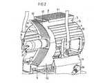
- the cooling shafts formed between the cooling fins 6 are dimensioned so that an optimal, fast, laminar air flow is ensured to dissipate the heat generated by the lamp 2.
- the dependence of the heat flow per shaft width depending on the width of the gap 60 between the individual cooling fins 6 with different shaft heights as parameters and the heat flow per shaft width depending on the shaft height with different gap thicknesses can be determined as a parameter at different wall temperatures of the cooling fins 6 and applied as a curve.
- cooling fins 6 can also be bent outwards at their upper end and thus support the lateral removal of the heated air.
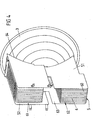
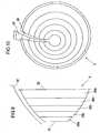
- reflector 3 is a recess 36 created for a cooling flow by a sector-shaped range of facets 33 of the reflector 3 is released and covered by a radially spaced, as seen from the reflector axis behind the actual reflector 3 arranged sector 34 '.
- the sector 34 ' is formed by a plurality of columns of facets 33 and extends substantially parallel to the original surface of the reflector 3 in the region of its recess 36. From the Fig.
Landscapes
- Engineering & Computer Science (AREA)
- General Engineering & Computer Science (AREA)
- Physics & Mathematics (AREA)
- General Physics & Mathematics (AREA)
- Non-Portable Lighting Devices Or Systems Thereof (AREA)
- Transforming Electric Information Into Light Information (AREA)
- Projection Apparatus (AREA)
- Arrangement Of Elements, Cooling, Sealing, Or The Like Of Lighting Devices (AREA)
Abstract
Claims (30)
- Projecteur, comprenant un boîtier de projecteur (1) dans lequel sont agencés une douille (4) pour la réception d'un moyen d'éclairage (2), un réflecteur (3) qui réfléchit les rayons lumineux émis par le moyen d'éclairage (2) en direction d'une ouverture de sortie de lumière du boîtier de projecteur (1), et un moyen de refroidissement (5, 51, 52 ; 6, 60-64) par convection qui enferme au moins partiellement le moyen d'éclairage (2), ce moyen de refroidissement engendrant un courant de convection pour l'évacuation de la chaleur émise par le moyen d'éclairage (2) et comprenant plusieurs lamelles de refroidissement (6) regroupées en paquets de lamelles de refroidissement (61, 62), caractérisé en ce que
l'axe longitudinal du moyen d'éclairage (2) est agencé sur l'axe optique du projecteur, en ce que les lamelles de refroidissement (6) s'étendent orientées parallèlement ou inclinées les unes par rapport aux autres des deux côtés d'un premier plan qui est orienté perpendiculairement à un axe d'inclinaison, passant par deux paliers de rotation agencés latéralement par rapport au boîtier de projecteur (1), du projecteur, et qui recoupe simultanément les paquets de lamelles de refroidissement (61, 62) et le moyen d'éclairage (2), et en ce que les paquets de lamelles de refroidissement (61, 62) sont agencés au-dessus et au-dessous d'un second plan qui s'étend perpendiculairement au premier plan le long de l'axe optique du projecteur. - Projecteur selon la revendication 1, caractérisé en ce que les lamelles de refroidissement (6) s'étendent essentiellement sur la totalité de la hauteur du projecteur.
- Projecteur selon la revendication 1 ou 2, caractérisé en ce que les paquets de lamelles de refroidissement (61, 62) sont limités par des tôles latérales (51, 52) sur les deux côtés pour constituer un caisson de refroidissement (5) par convection.
- Projecteur selon l'une au moins des revendications précédentes, caractérisé en ce que les lamelles de refroidissement (6) sont inclinées, lors d'un échauffement asymétrique, les unes par rapport aux autres de telle façon que dans tous les intervalles (60) formés entre les lamelles de refroidissement (6), un écoulement d'air de refroidissement essentiellement laminaire reste maintenu.
- Projecteur selon l'une au moins des revendications précédentes, caractérisé en ce que l'épaisseur des intervalles (60) formés entre les lamelles de refroidissement (6) est déterminé au moins en fonction de la température de parois des lamelles de refroidissement (6) et de la hauteur des paquets de lamelles de refroidissement (61, 62).
- Projecteur selon l'une au moins des revendications précédentes, caractérisé en ce que la largeur du caisson de refroidissement (5) par convection est essentiellement adaptée à la largeur du moyen d'éclairage (2).
- Projecteur selon l'une au moins des revendications précédentes, caractérisé en ce que le moyen de refroidissement (5, 51, 52 ; 6, 60-64) engendre un écoulement d'air de refroidissement laminaire sensiblement rapide.
- Projecteur selon l'une au moins des revendications précédentes, caractérisé en ce que les lamelles de refroidissement (6) sont réalisées au moins partiellement avec des longueurs différentes.
- Projecteur selon la revendication 8, caractérisé en ce que les lamelles de refroidissement (6) agencées au milieu sont plus longues que les lamelles de refroidissement extérieures (10).
- Projecteur selon l'une au moins des revendications précédentes, caractérisé en ce que les extrémités, de préférence supérieures, des lamelles de refroidissement (6) sont cintrées vers les côtés des plusieurs lamelles de refroidissement (6).
- Projecteur selon l'une au moins des revendications précédentes, caractérisé en ce que le paquet de lamelles de refroidissement (61) supérieur ou bien le caisson de refroidissement (5) par convection est sorti hors de la partie supérieure (12) du boîtier de projecteur (1) et est recouvert par une plaque de couverture (8).
- Projecteur selon la revendication 11, caractérisé en ce que la plaque de couverture (8) comporte des extrémités (81, 82) coudées vers le boîtier de projecteur (1).
- Projecteur selon l'une au moins des revendications précédentes, caractérisé en ce que le caisson de refroidissement (5) par convection reçoit la douille (4) pour le moyen d'éclairage dans l'espace intermédiaire (63) formé entre le paquet de lamelles de refroidissement supérieur et le paquet de lamelles de refroidissement inférieur (61, 62).
- Projecteur selon la revendication 13, caractérisé en ce que la douille (4) pour le moyen d'éclairage comporte des reliefs ou des découpes (40) supérieures et inférieures à la manière d'un peigne, dans lesquelles s'engagent au moins une partie des lamelles de refroidissement (6) avec un jeu de mobilité.
- Projecteur selon l'une au moins des revendications précédentes, caractérisé en ce que les arêtes (64), antérieures dans la direction de rayonnement du projecteur, des lamelles de refroidissement (6) sont adaptées à la forme de réflecteur (3) et enferment sensiblement le réflecteur (3).
- Projecteur selon la revendication de 15, caractérisé en ce que les arêtes antérieures (63) des lamelles de refroidissement (6) touchent le réflecteur (3).
- Projecteur selon la revendication de 15 ou 16, caractérisé en ce que les lamelles de refroidissement (6) sont fixées sur le réflecteur (3).
- Projecteur selon l'une au moins des revendications précédentes, caractérisé en ce que la face postérieure du réflecteur (3) est dotée de lamelles de refroidissement qui s'engagent à la manière d'un peigne dans les fentes (60) ménagées entre les lamelles de refroidissement (6) du caisson de refroidissement (5) par convection.
- Projecteur selon l'une au moins des revendications précédentes, caractérisé en ce que le réflecteur (3) comporte des ouvertures d'aération qui débouchent dans les fentes (60) ménagées entre les lamelles de refroidissement (6).
- Projecteur selon l'une au moins des revendications précédentes, comprenant un réflecteur à facettes avec une pluralité de facettes agencées en forme d'anneau autour du milieu du réflecteur suivant des lignes et des colonnes et formant une surface réfléchissante, caractérisé en ce qu'une zone du réflecteur (3), de forme annulaire comprenant une ou plusieurs lignes de facettes (33), est laissée libre et ménage ainsi une échancrure (36) dans la zone du réflecteur (3), à travers laquelle peut s'écouler un courant d'air de refroidissement à travers le réflecteur (3).
- Projecteur selon l'une au moins des revendications précédentes, comprenant un réflecteur à facettes avec une pluralité de facettes agencées en forme d'anneau autour du milieu du réflecteur suivant des lignes et des colonnes en formant une surface réfléchissante, caractérisé en ce qu'une région du réflecteur (3), comprenant une ou plusieurs colonnes (34) de facettes (33), est laissée libre et ménage ainsi une échancrure (36) dans la surface du réflecteur (3), à travers laquelle peut s'écouler un courant d'air de refroidissement à travers le réflecteur (3).
- Projecteur selon l'une des revendications 20 ou 21, caractérisé en ce que l'échancrure (36) est recouverte par un tronçon (34', 35b'), formé par des facettes réfléchissantes (33), qui est écarté radialement de la surface de réflecteur (3) et s'étend approximativement parallèlement à la surface du réflecteur (3) proprement dit.
- Projecteur selon la revendication 22, caractérisé en ce que le tronçon formé pour recouvrir l'échancrure (36) est constitué de facettes (33), dont la conformation de surface et l'agencement sont tels que le réflecteur (3) engendre la répartition de lumière souhaitée.
- Projecteur selon l'une au moins des revendications précédentes, caractérisé en ce qu'une tôle d'évacuation thermique (7) est agencée entre le réceptacle en verre (21) et les pointes de contact du moyen d'éclairage (2) et est orientée vers les paquets de lamelles de refroidissement (61, 62).
- Projecteur selon la revendication 24, caractérisé en ce que la tôle d'évacuation thermique (7) est réalisée en forme de V, U ou S.
- Projecteur selon la revendication 24 ou 25, caractérisé en ce que la tôle d'évacuation thermique (7) est reliée au socle (22) du moyen d'éclairage.
- Projecteur selon la revendication 26, caractérisé en ce que la tôle d'évacuation thermique (7) est enfichée sur le socle (22) du moyen d'éclairage.
- Projecteur selon la revendication 24 ou 25, caractérisé en ce que la tôle d'évacuation thermique (7) est reliée à la douille (4) pour le moyen éclairage, en particulier aux organes de serrage de lampe pour le moyen d'éclairage.
- Projecteur selon l'une au moins des revendications précédentes, caractérisé en ce que le moyen éclairage (2), qui présente un contour de forme essentiellement cylindrique, est orienté en direction axiale du projecteur et est mis en place dans une ouverture centrale du réflecteur (3).
- Projecteur selon la revendication 29, caractérisé en ce que le moyen d'éclairage (2) et le réflecteur (3) sont déplaçables l'un par rapport à l'autre en direction axiale.
Applications Claiming Priority (2)
| Application Number | Priority Date | Filing Date | Title |
|---|---|---|---|
| DE102005029671A DE102005029671A1 (de) | 2005-06-22 | 2005-06-22 | Kühlsystem für einen Scheinwerfer |
| PCT/EP2006/005950 WO2006136387A1 (fr) | 2005-06-22 | 2006-06-14 | Systeme de refroidissement pour un projecteur |
Publications (2)
| Publication Number | Publication Date |
|---|---|
| EP1902252A1 EP1902252A1 (fr) | 2008-03-26 |
| EP1902252B1 true EP1902252B1 (fr) | 2011-02-23 |
Family
ID=36809044
Family Applications (1)
| Application Number | Title | Priority Date | Filing Date |
|---|---|---|---|
| EP06743179A Active EP1902252B1 (fr) | 2005-06-22 | 2006-06-14 | Systeme de refroidissement pour un projecteur |
Country Status (5)
| Country | Link |
|---|---|
| US (1) | US9121589B2 (fr) |
| EP (1) | EP1902252B1 (fr) |
| JP (1) | JP4880680B2 (fr) |
| DE (2) | DE102005029671A1 (fr) |
| WO (1) | WO2006136387A1 (fr) |
Families Citing this family (5)
| Publication number | Priority date | Publication date | Assignee | Title |
|---|---|---|---|---|
| TWI346832B (en) * | 2007-07-25 | 2011-08-11 | Delta Electronics Inc | Illumination system adapted for a projection apparatus and cooling air guiding apparatus thereof |
| US20100073956A1 (en) * | 2008-09-23 | 2010-03-25 | Edison Opto Corporation | Heat dissipation module with light guiding fins |
| FR3022973A1 (fr) * | 2014-06-27 | 2016-01-01 | Valeo Vision | Reflecteur optique avec refroidisseur |
| JP2016162725A (ja) * | 2015-03-05 | 2016-09-05 | 株式会社東芝 | 照明装置 |
| CN105953145B (zh) * | 2016-07-04 | 2019-04-12 | 广州市浩洋电子股份有限公司 | 一种高效散热的防水舞台灯 |
Family Cites Families (22)
| Publication number | Priority date | Publication date | Assignee | Title |
|---|---|---|---|---|
| US1758290A (en) | 1928-06-29 | 1930-05-13 | Mccormack William Eugene | Lantern body for cinematograph and other projection apparatus |
| DE3808086A1 (de) * | 1988-03-11 | 1989-09-28 | Hella Kg Hueck & Co | Reflektor fuer abgeblendete oder abblendbare kraftfahrzeugscheinwerfer |
| EP0389659A1 (fr) * | 1989-03-30 | 1990-10-03 | Siemens Aktiengesellschaft | Projecteur |
| US4994948A (en) * | 1990-04-16 | 1991-02-19 | Corning Incorporated | Concave light reflector |
| US5172975A (en) | 1992-04-27 | 1992-12-22 | Mole-Richardson Co. | Light assembly with ventilated housing |
| JPH0750494A (ja) * | 1993-08-06 | 1995-02-21 | Mitsubishi Electric Corp | 冷却装置 |
| US5515254A (en) | 1995-03-07 | 1996-05-07 | High End Systems, Inc. | Automated color mixing wash luminaire |
| EP0751339A3 (fr) | 1995-06-30 | 1998-05-06 | CUNNINGHAM, David W. | Dispositif d'éclairage comprenant un réflecteur moulé |
| US6435699B2 (en) * | 1999-12-03 | 2002-08-20 | Texas Instruments Incorporated | Lamp housing with controlled cooling |
| TW568988B (en) * | 2001-03-26 | 2004-01-01 | Benq Corp | Light device with cooling means |
| JP2002313119A (ja) * | 2001-04-13 | 2002-10-25 | Hitachi Ltd | 投影装置用光源及びそれを用いた投写型画像ディスプレイ装置 |
| JP3987366B2 (ja) * | 2001-10-11 | 2007-10-10 | 三菱電機株式会社 | 光源装置及び投写型表示装置 |
| JP4096598B2 (ja) * | 2001-11-06 | 2008-06-04 | 株式会社日立製作所 | 投影装置用光源及びそれを用いた投写型画像ディスプレイ装置 |
| US6720566B2 (en) * | 2002-08-20 | 2004-04-13 | Miltec Corporation | Shutter for use with a light source |
| DE20214874U1 (de) | 2002-09-20 | 2003-11-06 | Arnold & Richter Cine Technik GmbH & Co Betriebs KG, 80799 München | Scheinwerfer |
| US7210825B2 (en) * | 2002-12-16 | 2007-05-01 | Victor Company Of Japan, Ltd. | Light source device |
| JP3855955B2 (ja) * | 2003-03-28 | 2006-12-13 | セイコーエプソン株式会社 | 光源装置及びプロジェクタ |
| JP2004303448A (ja) | 2003-03-28 | 2004-10-28 | Sharp Corp | 光源装置 |
| DE10316506A1 (de) * | 2003-04-09 | 2004-11-18 | Schott Glas | Lichterzeugende Vorrichtung mit Reflektor |
| WO2005008329A1 (fr) * | 2003-07-16 | 2005-01-27 | Matsushita Electric Industrial Co., Ltd. | Dispositif de source lumineuse, dispositif d'eclairage, et dispositif d'eclairage du type pour projection |
| ATE484710T1 (de) * | 2004-04-02 | 2010-10-15 | Martin Professional As | Lichtquellenmodul |
| WO2006029507A1 (fr) * | 2004-09-13 | 2006-03-23 | Her Majesty The Queen In Right Of Canada As Represented By The Minister Of Health | Inhibition de la replication de calicivirus felin par l'asparaginase |
-
2005
- 2005-06-22 DE DE102005029671A patent/DE102005029671A1/de not_active Withdrawn
-
2006
- 2006-06-14 EP EP06743179A patent/EP1902252B1/fr active Active
- 2006-06-14 US US11/922,712 patent/US9121589B2/en active Active
- 2006-06-14 WO PCT/EP2006/005950 patent/WO2006136387A1/fr not_active Ceased
- 2006-06-14 DE DE502006008948T patent/DE502006008948D1/de active Active
- 2006-06-14 JP JP2008517405A patent/JP4880680B2/ja active Active
Also Published As
| Publication number | Publication date |
|---|---|
| DE502006008948D1 (de) | 2011-04-07 |
| US9121589B2 (en) | 2015-09-01 |
| DE102005029671A1 (de) | 2006-12-28 |
| JP4880680B2 (ja) | 2012-02-22 |
| WO2006136387A1 (fr) | 2006-12-28 |
| EP1902252A1 (fr) | 2008-03-26 |
| JP2008544320A (ja) | 2008-12-04 |
| US20090027890A1 (en) | 2009-01-29 |
Similar Documents
| Publication | Publication Date | Title |
|---|---|---|
| DE102004017454B4 (de) | Scheinwerfer für Fahrzeuge | |
| EP0446423A1 (fr) | Dispositif d'éclairage | |
| DE102008036194A1 (de) | Lichtmodul für eine Beleuchtungseinrichtung für ein Kraftfahrzeug | |
| EP2278218A2 (fr) | Phare avant doté d'un dispositif de refroidissement | |
| DE10121658B4 (de) | Leuchtvorrichtung mit hoher Wärmediffusions-Wirksamkeit | |
| EP2149748B1 (fr) | Phare pour véhicules | |
| EP1902252B1 (fr) | Systeme de refroidissement pour un projecteur | |
| EP1896771B1 (fr) | Phare | |
| EP1915569B1 (fr) | Systeme de refroidissement pour projecteur | |
| EP3911892B1 (fr) | Luminaire avec dissipateur thermique fermé sur la périphérie | |
| DE19603025C2 (de) | Beleuchtungsvorrichtung zur Einspeisung von Licht in Lichtleitfasern | |
| DE202012101368U1 (de) | Leuchte | |
| DE10101005B4 (de) | Kraftfahrzeugleuchte, insbesondere Scheinwerfer | |
| US20060044777A1 (en) | Spotlight | |
| DE102009058308B4 (de) | Reflektor für Leuchten mit Ellipsoid-Facetten | |
| DE102013007155A1 (de) | Fahrzeugscheinwerfer | |
| DE1115656B (de) | Reflektoranordnung fuer langgestreckte, roehrenfoermige Lichtquellen | |
| DE102006061619B4 (de) | Fahrzeugscheinwerfer mit einem Projektionssystem | |
| DE9002879U1 (de) | Leuchte | |
| DE202024104938U1 (de) | Leuchte sowie Kühlkörper für eine Leuchte | |
| DE102012100005B4 (de) | Beleuchtungskörper mit geringem einfluss durch abwärme | |
| DE102010014338B4 (de) | Reflektorleuchte | |
| DE10120667A1 (de) | Leuchte mit einer Lampe mit gekühlter Kaltfußstelle | |
| DE102006057232A1 (de) | Fahrzeugscheinwerfer | |
| DE102014205471A1 (de) | Leuchte mit LED |
Legal Events
| Date | Code | Title | Description |
|---|---|---|---|
| PUAI | Public reference made under article 153(3) epc to a published international application that has entered the european phase |
Free format text: ORIGINAL CODE: 0009012 |
|
| 17P | Request for examination filed |
Effective date: 20080108 |
|
| AK | Designated contracting states |
Kind code of ref document: A1 Designated state(s): DE FR GB IT |
|
| DAX | Request for extension of the european patent (deleted) | ||
| RBV | Designated contracting states (corrected) |
Designated state(s): DE FR GB IT |
|
| 17Q | First examination report despatched |
Effective date: 20080801 |
|
| DAX | Request for extension of the european patent (deleted) | ||
| GRAP | Despatch of communication of intention to grant a patent |
Free format text: ORIGINAL CODE: EPIDOSNIGR1 |
|
| GRAS | Grant fee paid |
Free format text: ORIGINAL CODE: EPIDOSNIGR3 |
|
| GRAA | (expected) grant |
Free format text: ORIGINAL CODE: 0009210 |
|
| AK | Designated contracting states |
Kind code of ref document: B1 Designated state(s): DE FR GB IT |
|
| REG | Reference to a national code |
Ref country code: GB Ref legal event code: FG4D Free format text: NOT ENGLISH |
|
| REF | Corresponds to: |
Ref document number: 502006008948 Country of ref document: DE Date of ref document: 20110407 Kind code of ref document: P |
|
| REG | Reference to a national code |
Ref country code: DE Ref legal event code: R096 Ref document number: 502006008948 Country of ref document: DE Effective date: 20110407 |
|
| PLBE | No opposition filed within time limit |
Free format text: ORIGINAL CODE: 0009261 |
|
| STAA | Information on the status of an ep patent application or granted ep patent |
Free format text: STATUS: NO OPPOSITION FILED WITHIN TIME LIMIT |
|
| 26N | No opposition filed |
Effective date: 20111124 |
|
| REG | Reference to a national code |
Ref country code: DE Ref legal event code: R097 Ref document number: 502006008948 Country of ref document: DE Effective date: 20111124 |
|
| REG | Reference to a national code |
Ref country code: FR Ref legal event code: PLFP Year of fee payment: 10 |
|
| REG | Reference to a national code |
Ref country code: FR Ref legal event code: PLFP Year of fee payment: 11 |
|
| REG | Reference to a national code |
Ref country code: FR Ref legal event code: PLFP Year of fee payment: 12 |
|
| REG | Reference to a national code |
Ref country code: FR Ref legal event code: PLFP Year of fee payment: 13 |
|
| REG | Reference to a national code |
Ref country code: DE Ref legal event code: R082 Ref document number: 502006008948 Country of ref document: DE Representative=s name: ISARPATENT - PATENT- UND RECHTSANWAELTE BARTH , DE Ref country code: DE Ref legal event code: R082 Ref document number: 502006008948 Country of ref document: DE Representative=s name: ISARPATENT - PATENT- UND RECHTSANWAELTE PARTG , DE |
|
| PGFP | Annual fee paid to national office [announced via postgrant information from national office to epo] |
Ref country code: DE Payment date: 20250618 Year of fee payment: 20 |
|
| PGFP | Annual fee paid to national office [announced via postgrant information from national office to epo] |
Ref country code: GB Payment date: 20250620 Year of fee payment: 20 |
|
| PGFP | Annual fee paid to national office [announced via postgrant information from national office to epo] |
Ref country code: FR Payment date: 20250618 Year of fee payment: 20 |
|
| PGFP | Annual fee paid to national office [announced via postgrant information from national office to epo] |
Ref country code: IT Payment date: 20250630 Year of fee payment: 20 |