EP1902397B1 - Dispositif medical et procede permettant de regler un dispositif medical - Google Patents
Dispositif medical et procede permettant de regler un dispositif medical Download PDFInfo
- Publication number
- EP1902397B1 EP1902397B1 EP05748425A EP05748425A EP1902397B1 EP 1902397 B1 EP1902397 B1 EP 1902397B1 EP 05748425 A EP05748425 A EP 05748425A EP 05748425 A EP05748425 A EP 05748425A EP 1902397 B1 EP1902397 B1 EP 1902397B1
- Authority
- EP
- European Patent Office
- Prior art keywords
- value
- memory
- control unit
- medical apparatus
- screen
- Prior art date
- Legal status (The legal status is an assumption and is not a legal conclusion. Google has not performed a legal analysis and makes no representation as to the accuracy of the status listed.)
- Expired - Lifetime
Links
Images


Classifications
-
- A—HUMAN NECESSITIES
- A61—MEDICAL OR VETERINARY SCIENCE; HYGIENE
- A61M—DEVICES FOR INTRODUCING MEDIA INTO, OR ONTO, THE BODY; DEVICES FOR TRANSDUCING BODY MEDIA OR FOR TAKING MEDIA FROM THE BODY; DEVICES FOR PRODUCING OR ENDING SLEEP OR STUPOR
- A61M1/00—Suction or pumping devices for medical purposes; Devices for carrying-off, for treatment of, or for carrying-over, body-liquids; Drainage systems
- A61M1/14—Dialysis systems; Artificial kidneys; Blood oxygenators ; Reciprocating systems for treatment of body fluids, e.g. single needle systems for hemofiltration or pheresis
- A61M1/16—Dialysis systems; Artificial kidneys; Blood oxygenators ; Reciprocating systems for treatment of body fluids, e.g. single needle systems for hemofiltration or pheresis with membranes
- A61M1/1601—Control or regulation
- A61M1/1613—Profiling or modelling of patient or predicted treatment evolution or outcome
-
- G—PHYSICS
- G16—INFORMATION AND COMMUNICATION TECHNOLOGY [ICT] SPECIALLY ADAPTED FOR SPECIFIC APPLICATION FIELDS
- G16H—HEALTHCARE INFORMATICS, i.e. INFORMATION AND COMMUNICATION TECHNOLOGY [ICT] SPECIALLY ADAPTED FOR THE HANDLING OR PROCESSING OF MEDICAL OR HEALTHCARE DATA
- G16H40/00—ICT specially adapted for the management or administration of healthcare resources or facilities; ICT specially adapted for the management or operation of medical equipment or devices
- G16H40/60—ICT specially adapted for the management or administration of healthcare resources or facilities; ICT specially adapted for the management or operation of medical equipment or devices for the operation of medical equipment or devices
- G16H40/63—ICT specially adapted for the management or administration of healthcare resources or facilities; ICT specially adapted for the management or operation of medical equipment or devices for the operation of medical equipment or devices for local operation
-
- G—PHYSICS
- G16—INFORMATION AND COMMUNICATION TECHNOLOGY [ICT] SPECIALLY ADAPTED FOR SPECIFIC APPLICATION FIELDS
- G16Z—INFORMATION AND COMMUNICATION TECHNOLOGY [ICT] SPECIALLY ADAPTED FOR SPECIFIC APPLICATION FIELDS, NOT OTHERWISE PROVIDED FOR
- G16Z99/00—Subject matter not provided for in other main groups of this subclass
-
- A—HUMAN NECESSITIES
- A61—MEDICAL OR VETERINARY SCIENCE; HYGIENE
- A61M—DEVICES FOR INTRODUCING MEDIA INTO, OR ONTO, THE BODY; DEVICES FOR TRANSDUCING BODY MEDIA OR FOR TAKING MEDIA FROM THE BODY; DEVICES FOR PRODUCING OR ENDING SLEEP OR STUPOR
- A61M2205/00—General characteristics of the apparatus
- A61M2205/50—General characteristics of the apparatus with microprocessors or computers
- A61M2205/502—User interfaces, e.g. screens or keyboards
-
- A—HUMAN NECESSITIES
- A61—MEDICAL OR VETERINARY SCIENCE; HYGIENE
- A61M—DEVICES FOR INTRODUCING MEDIA INTO, OR ONTO, THE BODY; DEVICES FOR TRANSDUCING BODY MEDIA OR FOR TAKING MEDIA FROM THE BODY; DEVICES FOR PRODUCING OR ENDING SLEEP OR STUPOR
- A61M2205/00—General characteristics of the apparatus
- A61M2205/50—General characteristics of the apparatus with microprocessors or computers
- A61M2205/52—General characteristics of the apparatus with microprocessors or computers with memories providing a history of measured variating parameters of apparatus or patient
Definitions
- the invention relates to a medical apparatus and to a method for setting up a medical apparatus.
- the medical apparatus of the invention could be an apparatus intended for the extracorporeal treatment of blood, for instance by hemodialysis, hemofiltration, hemodialfitration, ultrafiltration, plasmapheresis or an apparatus for processing whole blood and/or blood components.
- Blood treatment apparatus and similar medical devices comprise an extracorporeal circuit, provided with at least one blood treatment or blood processing unit, one tube, connecting a blood removal zone to said unit, and a second tube, extending downstream of the treatment or processing unit towards a blood return zone to the patient or towards a blood/blood components collection zone. Blood is moved from the patient or donor to the treatment or processing unit via pumps or other actuators controlled by the machine.
- an adequately prepared dialysis liquid shall be sent to the treatment unit, water removal through the treatment unit membrane as well other machine parameters shall be controlled.
- a user can have the possibility to set a number of parameters in order to impose a specific prescription to a patient, such as for instance: flow rates of the various liquids, temperatures and conductivity of the liquids, concentration of the liquids used during treatment, flow rates of any anticoagulants used and delivered during treatment, pressures in the fluid conduits, net liquid removal rates of plasma water from whole blood and so on.
- variable parameters i.e. parameters that can vary in the course of time during treatment.
- US5247434 shows a method of programming a time-varying parameter comprising the steps:
- US5326476 is known a further method for entering a time variable parameter, ultrafiltration in particular, in a hemodialysis machine, having a programmable memory and having ultrafiltration capability, so as to enable the machine to perform ultrafiltration of fluid from a patient according to a time-variable ultrafiltration profile.
- the method disclosed in US5326476 comprises the following steps:
- This method allows the user to enter a profile curve and to move the ultrafiltration profile along the ordinates so as to achieve the desired integral value in the desired time frame.
- a further system for a dialysis machine is known from document US5788851 and comprises:
- the above system is therefore using two processing units in order to insure that unsafe parameters values are entered into the machine.
- the present invention aims to further improve ease and reliability in data entry procedures, particularly for blood treatment machines.
- the invention aims to offer a reliable and automated procedure for verifying proper memorization of entries.
- the invention aims to render reliable the storing of data on at least two distinct memory areas reducing the need for verification by the user.
- a method according to the invention is defined in claim 29.
- a software program according to the invention is defined in claim 31.
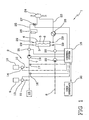
- reference number 1 denotes a medical apparatus according to the invention.
- the medical apparatus of the embodiment is a machine for the extracorporeal treatment of blood.
- the medical apparatus of the invention could alternatively be a blood processing device or a blood component preparation device or a medical fluid delivery/collection device.
- the apparatus shown in the enclosed drawings comprises a module 2 for preparing dialysis liquid to be sent into a first chamber 3 of a blood treatment unit 4, which is formed by a casing defining at least two chambers 3,5 separated by a semipermeable membrane 6.
- the dialysis preparation module 2 includes tubing 7 bringing dialysis liquid to the first chamber inlet, while a waste line 8 receives spent liquid exiting via an outlet of the first chamber.
- the module 2 includes one or more concentrate containers 9, 10 delivering concentrated solutions, via respective lines 11, 12 and upon the action of respective concentrate pumps 13, 14, into the tubing 7 thereby properly mixing water coming from a source 15 with said concentrates and obtaining the dialysis liquid.
- Conductivity or concentration sensors 16, 17 can be provided on tubing 7 downstream each respective concentrate line.
- Said sensors provide control signals to a control system 18 which is responsible to then act on the concentrate pumps.
- a pump 19 is generally operating on tubing 7 and a pump 20 on the waste line 8.
- fluid balance sensors for instance a first and a second flow-meter 21, 22, operating on tubing 7 and on waste line 8 respectively, are used and are connected to the control system to provide signals necessary for regulating at least one of pumps 19, 20.
- an extracorporeal blood circuit is connected to the second chamber 5.
- the extracorporeal circuit usually comprises at least one access branch 23 extending between a blood removal zone 24 from a patient or donor and the treatment unit 4, at least a return branch 25 extending downstream of the treatment unit, between the second chamber and a return zone of the blood to the patient; a peristaltic pump 26 is operatively associated to a length of pump tube of the extracorporeal circuit access branch.
- a clamp or other closure device can operate on the blood return branch 25, typically downstream of a gas separator 28.
- access means are provided to the cardiovascular system of the patient, for example constituted by needles of appropriate sizes, catheters or accesses of different types.
- One or more liquid infusion lines could be provided connected at one end to an infusion liquid source (a respective bag or an on-line infusion liquid preparation system) and at the other end to the extracorporeal circuit, or directly to the patient or donor.
- sensors such as pressure sensors 29, can be provided either on the extracorporeal circuit and/or on the dialysis liquid side of the apparatus.
- the apparatus 1 presents at least a user interface 30 for enabling setting of a plurality of parameters pertinent to operation of said apparatus or pertinent to a treatment to be performed by said apparatus.
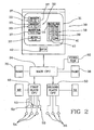
- a non-limiting embodiment of a user interface is schematically represented in figure 2 .
- the user interface 30 includes a screen 31 for visualization of values of said parameters.
- four apparatus operation parameters 32 are displayed and can be set by the user, namely conductivity, temperature, pH and flow rate of the dialysis liquid.
- the specific page shown on the screen of figure 2 is purely exemplifying and one among a plurality the apparatus is programmed to display in the course of apparatus set up for allowing data entry.
- the screen of the user interface is operable to show the set values 33 a user has input for the parameters available for modification.
- the screen can be a touch screen as in the embodiment shown in figure 2 , or a normal CRT screen or a non-touch sensitive display device, depending upon the type of user interface, as it will be described here below in grater detail.
- control system 18 which is connected to the user interface, is responsive to actions by a user on said user interface, and controls operations of the apparatus by acting on a plurality of actuators (such as pumps 12, 13, 19, 20, 27, valve 27 and others) and by receiving signals by a plurality of sensors (such as for instance sensors 12, 13, 21, 22, 29 etcetera).
- actuators such as pumps 12, 13, 19, 20, 27, valve 27 and others
- sensors such as for instance sensors 12, 13, 21, 22, 29 etcetera
- the control system includes a main control unit 34, connected to the user interface 30, a first memory 35 connected to the main control unit, a second memory 36 connected to the main control unit, a video memory 52 also connected to the main control unit and specifically devoted for storing data corresponding to images visualized or to be visualized on the screen.
- the main control unit includes a microprocessor, while the three above-mentioned memories can be in a single physical memory or in physically separated memory devices.
- the main control unit executes in use a program that renders the unit able to carry out the following steps allowing a user to entry one or more settings for a number of parameters.
- the control unit displays one or more indicia 37 on said screen corresponding to respective treatment parameters.
- the indicia can be icons representing the parameters or buttons or other specifically designated areas of the screen, which the user is allowed to select for identifying the parameter a user intends to modify.
- the selection of the indicium and therefore of the corresponding parameter can be done for instance by touching the indicium (if the screen is a touch screen or includes touch sensitive areas) or by acting on hard keys or hard toggles forming part of the user interface and operable for moving a cursor or for highlighting the indicium of the parameter a user intends to select.
- the touch screen 31 displays four button shaped indicia 37 which can be selected by touching the area of the screen delimited by each button.
- the dialysate flow button has been selected and the main control unit is programmed for sensing the selection (in this case the touch) made by the user and for moving the button from an unselected to a selected condition wherein said button is visually differentiated with respect to the unselected condition (this differentiation is not represented in figure 2 and may consist in one of the following: a modification of the background colour of the button compared to the unselected buttons background colour, and/or a modification of the border colour or thickness of the button compared to the unselected buttons border, and or a change in the shape of the selected button compared to the unselected ones, and/or a texturing of the selected button area, and/or a blinking of the selected button area or of parts thereof; of course any equivalent graphic means useful for emphasizing the selected condition can be adopted).
- the main control unit is also programmed for allowing setting of a new value for said parameter(s) and then storing the new value in the first memory 35.
- the new value can be entered in a number of ways, which will be here below described in detail.
- entry of a new setting for a parameter value comprises the following steps which are executed by the main control unit: the touch of the indicium is sensed and in response to said touching on the indicium the main control unit is programmed for invoking a data-entry pad 38 on the touch screen 31 (see figure 2 ).
- the data entry pad has a display region showing the value under modification and at least two set buttons 39, for instance keys allowing to increase or decrease the value in the display region.
- buttons 39 are present on the data entry pad, each button representing a corresponding digit to ease the entry of a desired set value.
- buttons 40 representing mathematical separators (comma or colon) and a cancel button 41 can also be present on the data entry pad.
- the control unit 34 is programmed for receiving a setting of a parametric value corresponding to the treatment parameter by touching one or more buttons of the data-entry pad. Once the setting has been completed the control unit detects the touching of an enter key 42 for signifying setting has been completed and entering the set value into the first memory 35.
- the enter key can be invoked on the data entry pad, or can be present in another part of the touch screen or, as shown in the embodiment of figure 2 , said enter key can be an hardware enter button positioned off the area of the screen.
- the main control unit 34 could be programmed for allowing entry of a parameter value according to the following steps.
- the control unit In response to a touching of a parameter indicium by the user the control unit is activating on the touch screen at least two set buttons 39 and an enter key 42 (these buttons and key could be already present on the touch screen and simply activated for modification of the selected parameter setting or could be invoked on the touch screen in response to said touching).
- No data entry pad is being invoked as the current value of the parameter(s) is shown on the screen in corresponding value display regions 43 even before selection of a specific parameter.
- a user can modify the setting by pressing one or both the arrow shaped buttons 39 on the right of the screen and then signify completion of the modification by pressing the enter key 42 on the touch screen.
- the main control unit detects the touching of said enter key for signifying settling has been completed and enters the newly set value in the first memory 35.
- the main control unit is programmed for capturing from the video memory 37 data representative of a region 44 of the screen where the value of the entered parameter is being graphically displayed. Then the main control unit verifies if the value graphically displayed in the region 44 corresponds to the value stored in the first memory 35.
- Figure 3 emphasizes a particular of the touch screen and schematically shows the above step of capturing from the video memory the image displayed in region 44.
- the main control unit is programmed to execute a first and a second task, each comprising a number of operative steps.
- the steps of allowing selection, modification and entry of the value in the first memory 35 are part of the first task executed in use by the main control unit.
- the step of capturing data from the video memory and the verification step are part of the second task executed by the control unit.
- the first and the second task are two separate software routines executed in use by the main control unit.
- the two tasks are working with a high degree of independence from each other: indeed the second task is activated upon receipt from the first task of a new set message informing the second task that a new parameter value has been entered.
- the control unit is programmed to work in multitasking mode: in particular the multitasking mode can be in time-share (in this case the control unit devotes prefixed time-shares to execute each task) or according to priority criteria. In any case it is advantageous that the message is sent by the first task only once the new value is stored in the first memory 35.
- the second task activities are activated only for a limited number of parameters.
- the first task provides for a step of detecting if the value under modification refers to safety relevant parameters, which are a subset of said plurality of parameters, and sends the message triggering activation of the second task only in case of modification in the setting of safety relevant parameters.
- the safety relevant parameters are one or more selected in the group comprising: temperature of the dialysis liquid, conductivity of the dialysis liquid, flow rate of the dialysis liquid, flow rate of the spent dialysate, flow rate of the blood in the extracorporeal circuit, ultrafiltration rate through the semipermeable membrane, net weight loss rate, treatment time, total weight loss.
- the second task also includes a step of storing the value in the second memory 36 if verification reveals identity between the value graphically represented in said region and the value entered in the first memory 35. Moreover if said verification reveals identity between the value graphically represented in said region and the value entered in the first memory, the main unit is programmed to execute a step of displaying on a zone of the screen distinct from said region the value stored either in the first memory or in the second memory.
- the verification step includes the steps of recognizing from said data the numeric value graphically represented in said region and comparing said numeric value to the entered value of the parameter stored in the first memory.
- Figure 4 shows that the region 44 of the screen where the value of the entered parameter is being displayed is separated in areas 45, each area being intended for the graphic representation of a single character forming said value.
- the main control unit recognizes the value displayed and contained in the video memory by referring to a plurality of sets of graphic data (for instance each set of graphic data can be a bitmap of each character expected to be entered by a user, including digits, mathematical symbols, mathematical operators).
- the recognition includes two sub-steps, namely the control unit first compares the captured data with pre-stored data patters: in so doing it is possible to see if known patters have been captured; in case the captured data do not match with anyone of the pre-stored data pattern, then an alarm is generated.
- the control unit compares the captured data referring to each area with the sets of graphic data for identifying the character corresponding to each sub-area.
- control unit can assemble the identified characters to form the numeric value displayed in said area and compare it with the corresponding value in the first memory 35.
- control unit could be programmed to consider the region 44 as a single area, compare the data representing the value displayed in said single area with known patterns and then if the value matches with one known pattern further proceed to checking if the value stored in the first memory corresponds to the value displayed in region 44.
- the verification step includes the steps of converting the value entered in the first memory in data graphically representing said value and comparing the data graphically representing the value entered in the first memory to said graphic data representative of the region of the screen where the value of the entered parameter is being displayed.
- the graphic data from the video memory 37 instead of converting the graphic data from the video memory 37 into a value and then compare two values, it is possible to apply the above mentioned bitmaps and graphically transform the value contained in the first memory into a graphic image as if it were to be displayed on a screen for then executing a comparison of the graphic image with the one in the video memory resulting from region 44 capture.
- the main control unit can also be programmed for capturing from video memory second data representative of a second region 46 of the screen where the name of the entered parameter is being displayed, and verifying if the name graphically displayed in said second region corresponds to a pre-stored name for the same parameter; also in this case if the verification step is positively passed, then the main control unit stores the name in the second memory 36.
- control unit makes reference to pre-stored patterns of known characters as for the detection of the value. As mentioned once the name displayed is recognized, the control unit compares said name with a pre-stored reference name for the same parameter to check whether there is identity or not.
- pre-stored names and pre-stored patterns of known data could significantly vary depending upon the language. It is therefore advantageous to store said reference pre-stored names and said reference pre-stored patterns on mass memory devices such as a flash memory, a hard disk, rewritable optical data carriers or other alternative mass storage means connected to the main control unit. In this way it is possible storing names and patterns customized to the language adopted by the machine, without changing the working of the control system.
- the mass storage device can be easily updated for new languages and or for enabling recognition of further names and patterns.
- the main control unit can be programmed for capturing from video memory third data representative of a third region 47 of the screen where the unit of measure (for instance a physical or chemical unit of measure) of the entered parameter is being displayed and for verifying if the unit graphically displayed in said third region corresponds to a pre-stored unit stored for the same parameter; if the verification step is positively passed, then the control unit stores the unit of measure in the second memory.
- the unit of measure for instance a physical or chemical unit of measure
- the control unit makes reference to pre-stored patterns of known characters as for the detection of the value or of the parameter name. Once the unit displayed is recognized, the control unit compares said unit with a pre-stored reference unit for the same parameter to check whether there is identity or not.
- pre-stored units and pre-stored patterns of known data could significantly vary depending upon the language and or the unit system adopted. It is therefore advantageous to store said reference pre-stored units of measure and said reference pre-stored patterns on mass memory devices such as a flash memory, a hard disk, rewritable optical data carriers or other alternative mass storage means connected to the main control unit. In this way it is possible storing units of measure and patterns customized to the language and unit system adopted by the machine, without changing the working of the control system.
- the mass storage device can be easily updated for new languages/unit systems and or for enabling recognition of further names and patterns.
- the starting of the screen region capturing step is triggered by a new set message sent by the first to the second task: in particular, the new set message contains the following information allowing the second task to perform the screen region capture:
- the message would contain also information on the coordinates (x 1 , y 1 , x 2 , y 2 ) of the screen region where the name is displayed and on coordinates (x 1 , y 1 , x 2 , y 2 ) of the screen region where the unit of measure is displayed.
- Cartesian coordinates are used, alterative coordinates such as polar systems or other equivalent coordinates serving to identify a region can be used.
- the main control unit is indeed programmed for periodically comparing the values of the parameters in the first memory to the values of the corresponding parameters in the second memory.
- the second task responsible for activating the comparison between values of the safety relevant parameters in the second memory with the corresponding values of safety relevant parameters in the first memory.
- the second task can activate an alarm procedure, which is not disclosed in detail as it does not form part of the present invention.
- the main control unit is also programmed for running a step of range checking to verify if the value that is being set is within a predetermined range of acceptable values, and a subsequent step of activating the possibility to enter in the first memory said set value only if said range checking step is positively passed.
- the user is prevented to enter in the first memory an out of range value as the first task operated by the main control unit checks if the value under modification is within a proper range. This is obtained by the main control unit either checking the entered value and activating the enter key only if the entered value is in a permissible range or by said unit preventing the user to even set an out of range value.
- the second task again executed by unit 34, provides for a range checking to verify if the newly entered value is within a predetermined range of acceptable values.
- the same control unit executes a first range check before entering the value (first task) and a second range check after entry and storage of the new value in the first memory 35, but before storing the same in the second memory 36.
- Another interesting feature of a possible embodiment provides that the main control unit 34 when executing the second task disables the possibility for modifying said region 44 (or regions (44, 46, 47) until the capturing step is completed. It should be noted indeed that during data entry other tasks and activities are normally running in the unit 34; these activities could in principle cause a modification of said region(s) 44, 46, 47 before completion of the capture thereby compromising the reliability of the entire process and causing false alarms.
- a first slave control unit 48 having a respective memory 49 is connected to the main control unit.
- a second slave control unit 50 is also connected to the main control unit but not directly connected to the first slave control unit; also the second slave control unit has a respective memory 51.
- a plurality of first actuators 53 are connected to and controlled by the slave control unit, but not directly controlled by the main control unit.
- the main control unit can send control messages to said first actuators only through the first slave control unit 48.
- a plurality of first sensors 54 connected to the first slave control unit is present: these first sensors are not directly connected to the main control unit but exchange information with this latter only via the first slave control unit.
- a plurality of second sensors 55 is connected to the second slave control unit and not directly connected to the main control unit. These second sensors exchange information with the main unit 34 only via the second slave control unit.
- the first and second sensors are connected only to the first and second slave units respectively.
- the first task sends the values of any entered parameters to the first slave control unit, this latter being programmed for saving said values in its memory and for controlling said actuators so that the difference between the actual values sensed by the first sensors for said parameters and the set values of the corresponding parameters is within a range of acceptability.
- the second task sends the values of safety relevant parameters entered in the second memory to said second slave control unit, this latter being programmed for storing said values in its memory and for signalling if the difference between the actual values sensed by the second sensors for said parameters and the set values of the corresponding parameters in the memory of the second slave unit is outside a range of acceptability.
- the main unit 34 via the first control unit, controls the actuators and, using its first sensors for feedback, makes sure to really control the actuators so that the current values of the parameters tend to match the desired set values.
- the second slave control unit verifies if the values stored in its memory (which are coming from the second task) are really in line with those detected by the second sensors and actuated by the first actuators. This control made by the second slave unit is performed using information coming from the second sensors, which are separated and independent from the first sensors.
- the first and second sensors can comprise pressure sensors (as those indicate with 29), flow sensors (21,22 in figure 1 ), temperature sensors (not shown), conductivity sensors (16, 17 in figure 1 ), pH sensors (not shown), etcetera.
- pressure sensors as those indicate with 29
- flow sensors 21,22 in figure 1
- temperature sensors not shown
- conductivity sensors (16, 17 in figure 1
- pH sensors not shown
- the nature and number of first and second sensors can vary depending upon the type of medical apparatus.
- the second task comprises the step of periodically comparing the values of the parameters in the second memory to the values of the corresponding parameters in the memory of the second slave unit.
- the apparatus 1 can include a plurality of first and second slave control units 48, 50 dedicated to corresponding subgroups of sensors and actuators.
- first slave units are connected to the main control unit and to the respective sensors and actuators but not directly connected to any of the second slave units.
- second slave units are connected to their respective second sensors and to the main unit but not directly connected to any first slave unit.
- the second slave unit in the attached drawing is not controlling any actuators; however it is possible to have a number of second actuators (such as valve 27 and/or pumps 19, 20, 26) connected to the second slave unit so that in case of alarm conditions the second unit can put the machine in safety conditions for the patient.
- a bypass line directly connecting conduit 7 and 8 and bypassing the treatment unit 4 is present and can be opened by an actuator (valve or pump) controlled by the second slave unit upon occurrence or certain particularly critical alarms.
- a user can see and modify the loaded set values in a prescription page; then he/she has to enter in a review page that summarizes all the prescription.
- the main control unit saves all the set values in the first memory and then sends to a message to the second task that triggers the capture of the screen of the whole page. Then the second task sends a message indicating that a review process is starting.
- the main control unit continues executing the first task which shows a busy indicator one screen and sends as many messages to the second task as there are safety relevant set values in the prescription.
- the second task For each message, the second task performs the same check described in the previous part of this description: it compares the name, value and units of measure to reference bitmaps to detect any failures.
- First task Second task • save all the values in the first memory • send the message to the second task • screen capture of the whole area • send the review message to the GUI • show a busy indicator • send the message for the first field to the second task • read the new value from the first memory • check the value • if ok, save it in the second memory otherwise generate alarm condition • send the message for the second field to the • second task • read the new value from the first memory • check the value • if ok, save it in the second memory otherwise generate an alarm condition • ... • send the message review end to the second task • send the message review end to the main control unit once all messages have been processed • delete the busy indicator and the review page
- the invention also concerns the method for setting up the above-described medical apparatuses, including a method for setting a blood treatment apparatus.
- the first steps of the method according to the invention are the setting of a new value for one or more parameters and the displaying of the new value of said parameter(s) in a region of the screen; the new value is stored in a normal memory, while the data representative of the region of the screen where at least the value of the entered parameter is being graphically displayed are stored in a video memory which can be part of the normal memory or not; the method then includes a step of capturing data representative of the region of the screen where at least the value of the entered parameter is being graphically displayed and a step of verifying if the value graphically displayed in the region (and represented by said representative data stored in the video memory) corresponds to the value stored in the normal memory. If said verification reveals identity between the value graphically represented in said region and the value entered in the memory, the method provides for storing said value in a further memory. In case of positive outcome of the verification the value is also displayed on the screen in an area distinct from the capture region.
- the method also provides for verification of the unit of measure and of the parameter name as described above for the apparatus and therefore not further repeated. Also the details of the capture and verification steps are as above disclosed and not herein repeated.
- the invention achieves important results.
Landscapes
- Health & Medical Sciences (AREA)
- Engineering & Computer Science (AREA)
- Biomedical Technology (AREA)
- Heart & Thoracic Surgery (AREA)
- Urology & Nephrology (AREA)
- Public Health (AREA)
- General Health & Medical Sciences (AREA)
- Hematology (AREA)
- Anesthesiology (AREA)
- Veterinary Medicine (AREA)
- Animal Behavior & Ethology (AREA)
- Emergency Medicine (AREA)
- Life Sciences & Earth Sciences (AREA)
- Vascular Medicine (AREA)
- Primary Health Care (AREA)
- Business, Economics & Management (AREA)
- General Business, Economics & Management (AREA)
- Epidemiology (AREA)
- Medical Informatics (AREA)
- External Artificial Organs (AREA)
- Electrotherapy Devices (AREA)
- Apparatus For Radiation Diagnosis (AREA)
Claims (32)
- Appareil médical (1) comprenant:au moins une interface utilisateur (30) pour permettre le réglage d'une pluralité de paramètres concernant le fonctionnement dudit appareil (1) ou concernant un traitement à exécuter par ledit appareil (1), l'interface utilisateur (30) comprenant au moins un écran (31) pour l'affichage des valeurs desdits paramètres,un système de commande (18) dans ledit appareil pour commander le fonctionnement dudit appareil médical (1) et réactif aux actions d'un utilisateur sur ladite interface utilisateur (30),ledit système de commande comprenant:une unité de commande principale (34) reliée à l'interface utilisateur (30),une première mémoire (35) reliée à l'unité de commande principale (34),une mémoire vidéo (52) elle-aussi reliée à l'unité de commande principale (34) pour mémoriser les données correspondant à des images affichées sur ledit écran (31), ladite unité de commande principale (34) étant programmée pour exécuter les étapes suivantes:permettre le réglage d'une nouvelle valeur pour au moins un paramètre;afficher la nouvelle valeur dans une région (44) de l'écran (31);mémoriser la nouvelle valeur dans la première mémoire (35);saisir de la mémoire vidéo (52) des données représentatives de ladite région (44) de l'écran (31) où au moins la valeur du paramètre introduit est affichée graphiquement;vérifier à partir desdites données représentatives si la valeur affichée graphiquement dans ladite région (44) correspond à la valeur mémorisée dans ladite première mémoire (35).
- Appareil médical selon la revendication 1, où le système de commande comprend une deuxième mémoire reliée à l'unité de commande principale (34), et où après ladite étape de vérification l'unité principale est programmée pour exécuter une étape de mémoriser la valeur dans la deuxième mémoire si ladite vérification montre l'identité entre la valeur représentée graphiquement dans ladite région (44) et la valeur introduite dans la première mémoire (35).
- Appareil médical selon la revendication 1, où l'étape de vérification comprend les étapes suivantes: identifier à partir desdites données la valeur numérique représentée graphiquement dans ladite région (44); et comparer ladite valeur numérique avec la valeur du même paramètre mémorisé dans la première mémoire (35).
- Appareil médical selon la revendication 1, où ladite étape de vérification comprend les étapes suivantes:faire référence à une pluralité de groupes de données graphiques, chaque groupe étant représentatif d'un modèle connu;comparer les données saisies avec les groupes de données graphiques pour déterminer si les données saisies contiennent un contenu identifiable;si les données saisies contiennent un contenu identifiable, comparer ledit contenu identifiable avec la valeur du paramètre mémorisé dans la première mémoire (35).
- Appareil médical selon la revendication 1, où l'étape de vérification comprend les étapes de convertir la valeur introduite dans la première mémoire (35) dans des données représentant graphiquement ladite valeur; comparer les données représentant graphiquement la valeur introduite dans la première mémoire (35) avec lesdites données représentatives de la région (44) de l'écran (31) où la valeur du paramètre introduit est affichée.
- Appareil médical selon la revendication 5, où ladite étape d'identification comprend les sous-étapes suivantes:faire référence à une pluralité de groupes de données graphiques, chaque groupe étant représentatif d'un modèle connu;convertir la valeur introduite dans la première mémoire (35) dans des données représentant graphiquement ladite valeur en employant lesdits groupes de données graphiques.
- Appareil médical selon la revendication 1, où:l'unité de commande principale (34) est programmée pour exécuter une première et une deuxième tâche,la première tâche, lorsqu'elle est exécutée par l'unité de commande, déterminant l'exécution desdites étapes de permettre la sélection, la modification et l'introduction de la valeur dans la première mémoire (35);la deuxième tâche, lorsqu'elle est exécutée par l'unité de commande, déterminant l'exécution de ladite étape de saisir les données de la mémoire vidéo (52) et de ladite étape de vérification;ladite deuxième tâche étant activée à la réception de la première tâche d'un nouveau message de réglage informant la deuxième tâche de l'introduction d'une nouvelle valeur de paramètre.
- Appareil médical selon la revendication 7, où ledit nouveau message est envoyé par l'unité de commande pendant l'exécution de la première tâche seulement lorsque la nouvelle valeur est mémorisée dans ladite première mémoire (35).
- Appareil médical selon la revendication 7, où ledit nouveau message de réglage contient les informations suivantes pour permettre à la deuxième tâche d'exécuter la saisie de la région de l'écran:des informations concernant l'identité du messagedes informations concernant les coordonnées de la région (44) de l'écran où la valeur est affichée.
- Appareil médical selon la revendication 7, où la deuxième tâche, lorsqu'elle est exécutée par l'unité de commande principale (34), cause l'étape de comparer périodiquement les valeurs des paramètres dans la première mémoire (35) avec les valeurs des paramètres correspondants dans la deuxième mémoire.
- Appareil médical selon la revendication 7, où la première tâche, lorsqu'elle est exécutée par l'unité de commande principale (34), détermine une étape de détecter si la valeur en train d'être modifiée se réfère à des paramètres de sécurité qui sont un sous-groupe de ladite pluralité de paramètres, ledit message est envoyé seulement en cas de modification dans le réglage de paramètres de sécurité.
- Appareil médical selon la revendication 1, où ladite étape de saisie comprend une étape de saisir de la mémoire vidéo (52) des deuxièmes données représentatives d'une deuxième région (46) de l'écran (31) où le nom du paramètre introduit est affiché, vérifier si le nom affiché graphiquement dans ladite deuxième région (46) correspond à un nom mémorisé préalablement pour le même paramètre.
- Appareil médical selon la revendication 1, où ladite étape de saisie comprend une étape de saisir de la mémoire vidéo (52) des troisièmes données représentatives d'une troisième région de l'écran (31) où l'unité de mesure pour le paramètre introduit est affiché, et vérifier si ladite unité affichée graphiquement dans ladite troisième région correspond à une unité de mesure mémorisée préalablement pour le même paramètre.
- Appareil médical selon la revendication 1, où ladite étape de permettre le réglage d'une nouvelle valeur comprend une étape de contrôle de l'intervalle pour vérifier si la valeur envoyée se trouve dans un intervalle prédéfini de valeurs acceptables, et une étape successive d'activer la possibilité d'introduire dans la première mémoire (35) ladite valeur réglée seulement si ladite étape de contrôle de l'intervalle a eu un résultat positif.
- Appareil médical selon la revendication 7, où ladite deuxième tâche, lorsqu'elle est exécutée par l'unité de commande principale (34), cause l'exécution des étapes consécutives suivantes après ladite étape de vérification:une étape de contrôle de l'intervalle vérifiant si la valeur envoyée se trouve dans un intervalle prédéfini de valeurs acceptables,une étape de mémoriser la valeur dans la deuxième mémoire si au moins toutes les deux conditions suivantes sont satisfaites: ladite vérification montre l'identité entre la valeur représentée graphiquement dans ladite région et la valeur introduite dans la première mémoire (35), et l'étape de contrôle de l'intervalle confirme que la valeur se trouve dans ledit intervalle prédéfini.
- Appareil médical selon la revendication 7, où la deuxième tâche, lorsqu'elle est exécutée par l'unité de commande principale (34), élimine la possibilité de modifier ladite région jusqu'à ce que l'étape de saisie n'est complétée.
- Appareil médical selon la revendication 1, où ladite unité de commande principale (34) est programmée pour exécuter les étapes suivantes avant de permettre le réglage d'une nouvelle valeur pour un paramètre:afficher une indication sur ledit écran (31) correspondant à un paramètre de traitement;permettre la sélection de l'indication pour identifier le paramètre qu'un utilisateur désire modifier.
- Appareil médical selon la revendication 17, où:l'écran (31) comprend un écran tactile,et où ladite étape de permettre la sélection de l'indication comprend la détection d'une touche de ladite indication,ladite étape de permettre le réglage d'une valeur de paramètre comprend les étapes suivantes:en réponse à ladite touche, invoquer un affichage d'introduction de données sur l'écran tactile, ledit affichage d'introduction de données ayant au moins deux boutons de réglage et une touche d'entrée;recevoir un réglage d'une valeur de paramètre correspondant au paramètre de traitement en appuyant sur un ou plusieurs boutons de l'affichage d'introduction de données;détecter la touche de ladite touche d'entrée montrant que le réglage a été complétée et introduire la valeur réglée.
- Appareil médical selon la revendication 17, où:l'écran (31) comprend un écran tactile,l'interface utilisateur (30) comprend au moins une touche fixe d'entrée à l'extérieur dudit écran tactile et reliée à l'interface utilisateur (30),et où:ladite étape de permettre la sélection de l'indication comprend la détection d'une touche de ladite indication,ladite étape de permettre le réglage d'une valeur de paramètre comprend les étapes suivantes:en réponse à ladite touche, invoquer un affichage d'introduction de données sur une région de l'écran tactile, ledit affichage d'introduction de données ayant au moins deux boutons de réglage;recevoir un réglage d'une valeur de paramètre correspondant au paramètre de traitement en appuyant sur un ou plusieurs boutons de l'affichage d'introduction de données;détecter la touche de ladite touche d'entrée montrant que le réglage a été complétée.
- Appareil médical selon la revendication 17, où:l'écran (31) comprend un écran tactile,et où ladite étape de permettre la sélection de l'indication comprend la détection d'une touche de ladite indication,et ou ladite étape de permettre le réglage d'une valeur de paramètre comprend les étapes suivantes:en réponse à ladite touche, activer sur l'écran tactile au moins deux boutons de réglage et une touche d'entrée;recevoir un réglage d'une valeur de paramètre correspondant au paramètre de traitement en appuyant sur un ou plusieurs boutons;détecter la touche de ladite touche d'entrée montrant que le réglage a été complétée.
- Appareil médical selon la revendication 11, comprenant un module de préparation de liquide de dialyse pour préparer le liquide de dialyse à envoyer dans une unité de traitement de sang, et au moins une ligne d'évacuation pour recevoir le dialysat usé éliminé de l'unité de traitement de sang.
- Appareil médical selon la revendication 21, comprenant: un tubage d'élimination de sang, un tubage de retour de sang et une unité de traitement de sang ayant un premier compartiment relié au module de préparation de liquide de dialyse et à la ligne d'évacuation, et un deuxième compartiment relié au tubage d'élimination de sang et au tubage de retour de sang, lesdits premier et deuxième compartiments étant séparés l'un de l'autre par une membrane semi-perméable.
- Appareil médical selon la revendication 22, où les paramètres de sécurité sont un ou plusieurs choisis dans le groupe comprenant:température du liquide de dialyse,conductivité du liquide de dialyse,débit du liquide de dialyse,débit du dialysat usé,débit du sang dans l'un desdits tubages,débit d'ultrafiltration à travers la membrane semi-perméable,taux de perte de poids net,durée du traitement,perte de poids.
- Appareil médical selon la revendication 7, comprenant:une première unité de commande principale esclave reliée à la première unité de commande (34), ladite première unité de commande esclave ayant une mémoire respective,une deuxième unité de commande principale esclave reliée à la première unité de commande (34), mais non reliée directement à la première unité de commande principale esclave, ladite deuxième unité de commande esclave ayant une mémoire respective,une pluralité de premiers actionneurs reliés à et commandés par l'unité de commande principale esclave et non commandés directement par l'unité de commande principale (34),une pluralité de premiers senseurs reliés à la première unité de commande esclave et non reliés directement à l'unité de commande principale (34),une pluralité de deuxièmes senseurs reliés à la deuxième unité de commande esclave et non reliés directement à l'unité de commande principale (34),la première tâche envoyant les valeurs de tout paramètre introduit à la première unité de commande esclave, cette dernière étant programmée pour sauvegarder lesdites valeurs dans sa mémoire et pour commander lesdits actionneurs de sorte que la différence entre les valeurs actuelles détectées par les premiers senseurs pour lesdits paramètres et les valeurs réglées des paramètres correspondants se trouve dans un intervalle d'acceptabilité, la deuxième tâche envoyant les valeurs de paramètres de sécurité introduits dans la deuxième mémoire à la deuxième unité de commande esclave, cette dernière étant programmée pour mémoriser lesdites valeurs dans sa mémoire et pour signaliser si la différence entre les valeurs actuelles détectées par les deuxièmes senseurs pour lesdits paramètres et les valeurs réglées des paramètres correspondants dans la mémoire de la deuxième unité esclave se trouve hors d'un intervalle d'acceptabilité.
- Appareil médical selon la revendication 24, où la deuxième tâche comprend l'étape de comparer périodiquement les valeurs des paramètres dans la deuxième mémoire avec les valeurs des paramètres correspondants dans la mémoire de la deuxième unité esclave.
- Appareil médical selon la revendication 1, où ladite unité de commande principale (34) est programmée pour exécuter l'étape de permettre le réglage d'une nouvelle valeur pour une pluralité de paramètres; afficher les nouvelles valeurs des paramètres dans une région (44) de l'écran (31); mémoriser les nouvelles valeurs dans la première mémoire (35); saisir de la mémoire vidéo (52) des données représentatives de régions de l'écran (31) où les valeurs des paramètres introduits sont affichées graphiquement; vérifier à partir desdites données représentatives si les valeurs affichées graphiquement dans lesdites régions correspondent aux valeurs mémorisées dans ladite première mémoire (35) pour les mêmes paramètres respectifs.
- Appareil médical selon la revendication 1, où, si ladite vérification montre l'identité entre la valeur représentée graphiquement dans ladite région et la valeur introduite dans la première mémoire (35), l'unité principale est programmée pour exécuter une étape d'afficher la valeur mémorisée dans la première mémoire (35) dans une zone de l'écran (31) différente de ladite région.
- Appareil médical selon la revendication 2, où l'unité principale est programmée pour exécuter une étape d'afficher la valeur mémorisée dans la deuxième mémoire dans une zone de l'écran (31) différente de ladite région.
- Méthode pour mettre en place un appareil médical (1) comprenant au moins une interface utilisateur (30) pour permettre le réglage d'une pluralité de paramètres concernant le fonctionnement dudit appareil (1) ou concernant un traitement à exécuter par ledit appareil (1), l'interface utilisateur (30) comprenant au moins un écran (31) pour l'affichage des valeurs desdits paramètres, un système de commande dans ledit appareil pour commander le fonctionnement dudit appareil médical (1) et réactif aux actions d'un utilisateur sur ladite interface utilisateur (30), le système de commande comprenant au moins une mémoire vidéo (52) pour mémoriser les données correspondant à des images affichées sur ledit écran (31),
la méthode comprenant les étapes suivantes:régler une nouvelle valeur pour un paramètre;afficher la nouvelle valeur dudit paramètre dans une région de l'écran (31);mémoriser la nouvelle valeur dans une première mémoire (35);saisir de la mémoire vidéo (52) des données représentatives de la région de l'écran (31) où au moins la valeur du paramètre introduit est affichée graphiquement;vérifier si la valeur affichée graphiquement dans ladite région correspond à la valeur mémorisée dans ladite première mémoire (35). - Méthode selon la revendication 29, comprenant après l'étape de vérification une étape de mémoriser la valeur dans une autre mémoire du système de commande si ladite vérification montre l'identité entre la valeur représentée graphiquement dans ladite région et la valeur introduite dans la mémoire.
- Programme logiciel comprenant des instructions qui, lorsqu'elles sont exécutées par l'unité de commande principale (34) de l'appareil selon la revendication 1, programment l'unité de commande pour exécuter les étapes définies à la revendication 29.
- Programme selon la revendication 30, où le programme est mémorisé sur un support choisi dans un groupe comprenant:- un support d'enregistrement magnétique,- un support d'enregistrement optique,- un signal porteur électrique,- un signal porteur électromagnétique,- une mémoire morte,- une mémoire vive
Applications Claiming Priority (1)
| Application Number | Priority Date | Filing Date | Title |
|---|---|---|---|
| PCT/IB2005/001617 WO2006131775A1 (fr) | 2005-06-09 | 2005-06-09 | Dispositif medical et procede permettant de regler un dispositif medical |
Publications (2)
| Publication Number | Publication Date |
|---|---|
| EP1902397A1 EP1902397A1 (fr) | 2008-03-26 |
| EP1902397B1 true EP1902397B1 (fr) | 2010-04-14 |
Family
ID=35509309
Family Applications (1)
| Application Number | Title | Priority Date | Filing Date |
|---|---|---|---|
| EP05748425A Expired - Lifetime EP1902397B1 (fr) | 2005-06-09 | 2005-06-09 | Dispositif medical et procede permettant de regler un dispositif medical |
Country Status (7)
| Country | Link |
|---|---|
| US (1) | US7922899B2 (fr) |
| EP (1) | EP1902397B1 (fr) |
| JP (1) | JP4653218B2 (fr) |
| AT (1) | ATE464611T1 (fr) |
| DE (1) | DE602005020697D1 (fr) |
| ES (1) | ES2344512T3 (fr) |
| WO (1) | WO2006131775A1 (fr) |
Families Citing this family (68)
| Publication number | Priority date | Publication date | Assignee | Title |
|---|---|---|---|---|
| US20080307353A1 (en) * | 2005-08-25 | 2008-12-11 | Gambro Lundia Ab | Medical Apparatus and User Interface for a Medical Apparatus |
| US10537671B2 (en) | 2006-04-14 | 2020-01-21 | Deka Products Limited Partnership | Automated control mechanisms in a hemodialysis apparatus |
| US10463774B2 (en) | 2007-02-27 | 2019-11-05 | Deka Products Limited Partnership | Control systems and methods for blood or fluid handling medical devices |
| US8409441B2 (en) | 2007-02-27 | 2013-04-02 | Deka Products Limited Partnership | Blood treatment systems and methods |
| KR20230165373A (ko) | 2007-02-27 | 2023-12-05 | 데카 프로덕츠 리미티드 파트너쉽 | 혈액투석 시스템 |
| US9308307B2 (en) | 2007-09-13 | 2016-04-12 | Fresenius Medical Care Holdings, Inc. | Manifold diaphragms |
| US8597505B2 (en) | 2007-09-13 | 2013-12-03 | Fresenius Medical Care Holdings, Inc. | Portable dialysis machine |
| US8040493B2 (en) | 2007-10-11 | 2011-10-18 | Fresenius Medical Care Holdings, Inc. | Thermal flow meter |
| US8240636B2 (en) | 2009-01-12 | 2012-08-14 | Fresenius Medical Care Holdings, Inc. | Valve system |
| US8105487B2 (en) | 2007-09-25 | 2012-01-31 | Fresenius Medical Care Holdings, Inc. | Manifolds for use in conducting dialysis |
| US8535522B2 (en) * | 2009-02-12 | 2013-09-17 | Fresenius Medical Care Holdings, Inc. | System and method for detection of disconnection in an extracorporeal blood circuit |
| US9358331B2 (en) | 2007-09-13 | 2016-06-07 | Fresenius Medical Care Holdings, Inc. | Portable dialysis machine with improved reservoir heating system |
| EP2237814B1 (fr) | 2007-11-29 | 2019-03-06 | Fresenius Medical Care Holdings, Inc. | Collecteur pour réaliser une hémodialyse et une hémofiltration |
| US11975128B2 (en) | 2008-01-23 | 2024-05-07 | Deka Products Limited Partnership | Medical treatment system and methods using a plurality of fluid lines |
| US10201647B2 (en) | 2008-01-23 | 2019-02-12 | Deka Products Limited Partnership | Medical treatment system and methods using a plurality of fluid lines |
| US11738130B2 (en) | 2008-01-23 | 2023-08-29 | Deka Products Limited Partnership | Fluid line autoconnect apparatus and methods for medical treatment system |
| US10195330B2 (en) | 2008-01-23 | 2019-02-05 | Deka Products Limited Partnership | Medical treatment system and methods using a plurality of fluid lines |
| US8323503B2 (en) | 2008-06-11 | 2012-12-04 | Fresenius Medical Care Holdings, Inc. | User interface processing device |
| US12171922B2 (en) | 2008-08-27 | 2024-12-24 | Deka Products Limited Partnership | Blood treatment systems and methods |
| EP3650056A1 (fr) * | 2008-08-27 | 2020-05-13 | DEKA Products Limited Partnership | Systèmes et procédés de traitement du sang |
| CA2976872C (fr) | 2008-10-07 | 2021-04-13 | Fresenius Medical Care Holdings, Inc. | Systeme et procede d'amorcage pour systemes de dialyse |
| NZ592652A (en) | 2008-10-30 | 2013-10-25 | Fresenius Med Care Hldg Inc | Modular, portable dialysis system |
| US9250106B2 (en) | 2009-02-27 | 2016-02-02 | Tandem Diabetes Care, Inc. | Methods and devices for determination of flow reservoir volume |
| US8573027B2 (en) | 2009-02-27 | 2013-11-05 | Tandem Diabetes Care, Inc. | Methods and devices for determination of flow reservoir volume |
| WO2010114932A1 (fr) | 2009-03-31 | 2010-10-07 | Xcorporeal, Inc. | Ensemble réservoir modulaire pour un système d'hémodialyse et d'hémofiltration |
| US8758323B2 (en) | 2009-07-30 | 2014-06-24 | Tandem Diabetes Care, Inc. | Infusion pump system with disposable cartridge having pressure venting and pressure feedback |
| JP2013509271A (ja) | 2009-10-30 | 2013-03-14 | デカ・プロダクツ・リミテッド・パートナーシップ | 血管アクセスデバイスの離脱を検知するための装置および方法 |
| US8753515B2 (en) | 2009-12-05 | 2014-06-17 | Home Dialysis Plus, Ltd. | Dialysis system with ultrafiltration control |
| JP5747072B2 (ja) * | 2010-04-16 | 2015-07-08 | バクスター・インターナショナル・インコーポレイテッドBaxter International Incorp0Rated | 腎不全血液療法、特に、在宅血液透析のための療法の予測および最適化 |
| EP2571546B1 (fr) * | 2010-05-21 | 2019-03-27 | Gambro Lundia AB | Interface utilisateur et machine |
| US8501009B2 (en) | 2010-06-07 | 2013-08-06 | State Of Oregon Acting By And Through The State Board Of Higher Education On Behalf Of Oregon State University | Fluid purification system |
| WO2012051278A1 (fr) | 2010-10-12 | 2012-04-19 | Tanis Kevin J | Dispositif médical |
| US20120124500A1 (en) * | 2010-11-16 | 2012-05-17 | Motorola Mobility, Inc. | Use of discrete input to control controllable device |
| US9408958B2 (en) | 2010-12-17 | 2016-08-09 | Fresenius Medical Care Holdings, Inc. | User interfaces for dialysis devices |
| US9999717B2 (en) | 2011-05-24 | 2018-06-19 | Deka Products Limited Partnership | Systems and methods for detecting vascular access disconnection |
| EP2763719B1 (fr) | 2011-10-07 | 2017-08-09 | Outset Medical, Inc. | Purification de fluide d'échange de chaleur pour un système de dialyse |
| EP3002989B1 (fr) | 2011-11-04 | 2017-04-19 | DEKA Products Limited Partnership | Système de traitement médical et procédés utilisant une pluralité de conduites de fluide |
| US12303631B2 (en) | 2011-11-04 | 2025-05-20 | Deka Products Limited Partnership | Medical treatment system and methods using a plurality of fluid lines |
| EP2659919B1 (fr) | 2012-05-03 | 2014-12-10 | B. Braun Avitum AG | Procédé de réglage de paramètres pertinents de sécurité dans un appareil médical et appareil médical |
| DE102012009517A1 (de) * | 2012-05-14 | 2013-11-14 | Fresenius Medical Care Deutschland Gmbh | Vorrichtung und Verfahren für die Eingabe von Benutzerinformationen in medizinische Geräte |
| US9238100B2 (en) | 2012-06-07 | 2016-01-19 | Tandem Diabetes Care, Inc. | Device and method for training users of ambulatory medical devices |
| US9201036B2 (en) | 2012-12-21 | 2015-12-01 | Fresenius Medical Care Holdings, Inc. | Method and system of monitoring electrolyte levels and composition using capacitance or induction |
| US9157786B2 (en) | 2012-12-24 | 2015-10-13 | Fresenius Medical Care Holdings, Inc. | Load suspension and weighing system for a dialysis machine reservoir |
| US10288881B2 (en) | 2013-03-14 | 2019-05-14 | Fresenius Medical Care Holdings, Inc. | Wearable interface for remote monitoring and control of a medical device |
| US9737649B2 (en) | 2013-03-14 | 2017-08-22 | Smith & Nephew, Inc. | Systems and methods for applying reduced pressure therapy |
| WO2014151930A2 (fr) | 2013-03-14 | 2014-09-25 | Smith & Nephew Inc. | Systèmes et procédés pour appliquer une thérapie par pression réduite |
| RU2016108629A (ru) | 2013-08-13 | 2017-09-19 | Смит Энд Нефью, Инк. | Системы и способы для применения терапии пониженным давлением |
| US9354640B2 (en) | 2013-11-11 | 2016-05-31 | Fresenius Medical Care Holdings, Inc. | Smart actuator for valve |
| US10966646B2 (en) * | 2014-04-07 | 2021-04-06 | Phlebotics, Inc. | Simplified blood sampling device and method |
| JP6657186B2 (ja) | 2014-04-29 | 2020-03-04 | アウトセット・メディカル・インコーポレイテッドOutset Medical, Inc. | 透析システムおよび方法 |
| US12026271B2 (en) | 2014-05-27 | 2024-07-02 | Deka Products Limited Partnership | Control systems and methods for blood or fluid handling medical devices |
| CN104281349B (zh) * | 2014-09-25 | 2016-11-09 | 京东方科技集团股份有限公司 | 双面触控基板、双面触控装置和双面触控显示装置 |
| US10430073B2 (en) | 2015-07-17 | 2019-10-01 | Crown Equipment Corporation | Processing device having a graphical user interface for industrial vehicle |
| US9839735B2 (en) | 2015-09-08 | 2017-12-12 | Fresenius Medical Care Holdings, Inc. | Voice interface for a dialysis machine |
| US11534537B2 (en) | 2016-08-19 | 2022-12-27 | Outset Medical, Inc. | Peritoneal dialysis system and methods |
| USD835648S1 (en) | 2016-10-27 | 2018-12-11 | Smith & Nephew, Inc. | Display screen or portion thereof with a graphical user interface for a therapy device |
| EP3545398B1 (fr) | 2016-11-22 | 2023-01-04 | Crown Equipment Corporation | Dispositif d'interface utilisateur pour véhicule industriel |
| US10842924B2 (en) | 2017-06-29 | 2020-11-24 | Fresenius Medical Care Deutschland Gmbh | Therapy control by comprehensive feedback |
| DE102018106906A1 (de) * | 2018-03-22 | 2019-09-26 | Fresenius Medical Care Deutschland Gmbh | Medizingerät |
| AU2019325668B2 (en) | 2018-08-23 | 2025-03-27 | Outset Medical, Inc. | Dialysis system and methods |
| US11679188B2 (en) * | 2019-04-23 | 2023-06-20 | Fenwal, Inc. | System and methods incorporating replacement fluid maximization |
| AU2020266584B2 (en) | 2019-04-30 | 2025-10-23 | Outset Medical, Inc. | Dialysis system and methods |
| EP3991764B1 (fr) | 2020-10-27 | 2024-03-06 | Bellco S.r.l. | Débitmètre pour dosage de l'eau dans un système de dialyse |
| US12318528B2 (en) | 2020-10-30 | 2025-06-03 | Mozarc Medical Us Llc | Variable orifice fistula graft |
| ES3007240T3 (en) | 2020-10-30 | 2025-03-19 | Bellco Srl | Dialysis cassette with pump features |
| EP4008376A1 (fr) | 2020-12-03 | 2022-06-08 | Medtronic, Inc. | Accessoire de routage de tubes flexibles pour système de dialyse péritonéale |
| JP7835037B2 (ja) * | 2022-02-16 | 2026-03-25 | ニプロ株式会社 | 血液浄化装置および血液浄化装置の制御方法 |
| CN115463275A (zh) * | 2022-08-03 | 2022-12-13 | 健帆生物科技集团股份有限公司 | 血液净化设备的控制方法、血液净化设备及计算机可读存储介质 |
Family Cites Families (52)
| Publication number | Priority date | Publication date | Assignee | Title |
|---|---|---|---|---|
| US4370983A (en) * | 1971-01-20 | 1983-02-01 | Lichtenstein Eric Stefan | Computer-control medical care system |
| US4228506A (en) * | 1978-11-09 | 1980-10-14 | Del Mar Avionics | Charter with automatic editing |
| US4291388A (en) * | 1978-12-20 | 1981-09-22 | Allen-Bradley Company | Programmable controller with data archive |
| SE457388B (sv) * | 1985-06-04 | 1988-12-19 | Gambro Ab | Monitor foer styrning och/eller kontroll av tvaa eller flera funktioner samt anvaendning av en saadan foer styrning av en vaetskestroem |
| JPS6479833A (en) | 1987-09-22 | 1989-03-24 | Toshiba Corp | Medical image diagnosing device |
| DE3905350A1 (de) | 1989-02-22 | 1990-09-06 | Braun Melsungen Ag | Medizintechnisches geraet mit redundant aufgebauter steuereinheit zur infusionstherapie oder blutbehandlung |
| US5564012A (en) * | 1989-03-29 | 1996-10-08 | Fuji Photo Film Co., Ltd. | Support apparatus for use with radiation image information processing system |
| JP2601542B2 (ja) | 1989-04-20 | 1997-04-16 | 富士写真フイルム株式会社 | 放射線画像情報処理システム用支援装置 |
| FR2645296A1 (fr) | 1989-03-31 | 1990-10-05 | Gen Electric Cgr | Procede et dispositif de reparation d'une memoire d'images |
| IT1235192B (it) * | 1989-05-31 | 1992-06-23 | Hospal Dasco Spa | Metodo di gestione di parametri connessi con un trattamento di dialisie macchina di dialisi implementante tale metodo |
| US5276611A (en) * | 1989-05-25 | 1994-01-04 | Andrea Ghiraldi | Management of parameters relating to a dialysis treatment |
| JPH03109648A (ja) | 1989-09-22 | 1991-05-09 | Hitachi Medical Corp | 医用画像処理装置 |
| US5326476A (en) * | 1991-04-19 | 1994-07-05 | Althin Medical, Inc. | Method and apparatus for kidney dialysis using machine with programmable memory |
| US5486286A (en) * | 1991-04-19 | 1996-01-23 | Althin Medical, Inc. | Apparatus for performing a self-test of kidney dialysis membrane |
| US5247434A (en) * | 1991-04-19 | 1993-09-21 | Althin Medical, Inc. | Method and apparatus for kidney dialysis |
| JPH05233344A (ja) | 1992-02-20 | 1993-09-10 | Hitachi Ltd | 情報処理装置 |
| JP2675968B2 (ja) * | 1992-08-20 | 1997-11-12 | インターナショナル・ビジネス・マシーンズ・コーポレイション | 加入者分散2相コミット・プロトコルの拡張機能 |
| US5300093A (en) * | 1992-09-14 | 1994-04-05 | Telectronics Pacing Systems, Inc. | Apparatus and method for measuring, formatting and transmitting combined intracardiac impedance data and electrograms |
| US5601435A (en) * | 1994-11-04 | 1997-02-11 | Intercare | Method and apparatus for interactively monitoring a physiological condition and for interactively providing health related information |
| JP2570592B2 (ja) | 1993-09-17 | 1997-01-08 | 日本電気株式会社 | インタラクティブ型マルチウインドウプログラム自動テスト装置 |
| US5617534A (en) * | 1994-02-16 | 1997-04-01 | Intel Corporation | Interface protocol for testing of a cache memory |
| US6256643B1 (en) * | 1998-03-10 | 2001-07-03 | Baxter International Inc. | Systems and methods for storing, retrieving, and manipulating data in medical processing devices |
| US5581687A (en) * | 1994-11-10 | 1996-12-03 | Baxter International Inc. | Interactive control systems for medical processing devices |
| US5788851A (en) * | 1995-02-13 | 1998-08-04 | Aksys, Ltd. | User interface and method for control of medical instruments, such as dialysis machines |
| US5620608A (en) | 1995-06-07 | 1997-04-15 | Cobe Laboratories, Inc. | Information entry validation system and method for a dialysis machine |
| JPH0947447A (ja) | 1995-08-10 | 1997-02-18 | Toshiba Corp | 画像診断装置 |
| SE510126C2 (sv) * | 1996-06-13 | 1999-04-19 | Althin Medical Ab | Dialysmaskin med rörlig manöverpanel |
| US5903211A (en) * | 1997-02-07 | 1999-05-11 | Althin Medical, Inc. | Medical treatment device with a user interface adapted for home or limited care environments |
| US6554789B1 (en) * | 1997-02-14 | 2003-04-29 | Nxstage Medical, Inc. | Layered fluid circuit assemblies and methods for making them |
| US5858239A (en) * | 1997-02-14 | 1999-01-12 | Aksys, Ltd. | Methods and apparatus for adjustment of blood drip chamber of dialysis machines using touchscreen interface |
| US6979309B2 (en) * | 1997-02-14 | 2005-12-27 | Nxstage Medical Inc. | Systems and methods for performing blood processing and/or fluid exchange procedures |
| DE19742633C2 (de) | 1997-09-26 | 2000-12-07 | Fresenius Medical Care De Gmbh | Vorrichtung und Verfahren zur Sicherung von Touchscreen-Bedienungen |
| DE19742637C5 (de) * | 1997-09-26 | 2005-06-02 | Fresenius Medical Care Deutschland Gmbh | Vorrichtung und Verfahren zur Bedienung medizintechnischer Geräte |
| SE9801121D0 (sv) | 1998-03-30 | 1998-03-30 | Astra Ab | Electrical device |
| FR2784765B1 (fr) * | 1998-10-19 | 2001-07-27 | Ela Medical Sa | Dispositif medical actif, comprenant des registres proteges pour l'ajustement numerique de parametres de fonctionnement |
| US6381557B1 (en) * | 1998-11-25 | 2002-04-30 | Ge Medical Systems Global Technology Company, Llc | Medical imaging system service evaluation method and apparatus |
| IT1310933B1 (it) * | 1999-11-16 | 2002-02-27 | Luigi Benatti | Macchina multifunzionale per il monitoraggio ed il controllo diterapie locoregionali in oncologia. |
| DE10013666B4 (de) | 2000-03-20 | 2006-04-20 | Fresenius Medical Care Deutschland Gmbh | Gerät zum Eingeben und Anzeigen von Soll- bzw. Grenzwerten |
| IT1320264B1 (it) * | 2000-09-29 | 2003-11-26 | Gambro Dasco Spa | Apparecchiatura di dialisi e metodo di verifica della funzionalita' diuna apparecchiatura di dialisi. |
| TW552130B (en) * | 2000-10-18 | 2003-09-11 | Ind Tech Res Inst | PC-based man-machine interface for medical ultrasonic diagnostic device |
| US6468241B1 (en) * | 2000-10-26 | 2002-10-22 | Chf Solutions, Inc. | Artificial kidney set with electronic key |
| US6773412B2 (en) * | 2001-04-13 | 2004-08-10 | Chf Solutions, Inc. | User interface for blood treatment device |
| US6685664B2 (en) * | 2001-06-08 | 2004-02-03 | Chf Solutions, Inc. | Method and apparatus for ultrafiltration utilizing a long peripheral access venous cannula for blood withdrawal |
| US6775577B2 (en) * | 2001-07-18 | 2004-08-10 | Fresenius Usa, Inc. | Method and system for controlling a medical device |
| US7051264B2 (en) * | 2001-11-14 | 2006-05-23 | Monolithic System Technology, Inc. | Error correcting memory and method of operating same |
| US7768522B2 (en) * | 2002-01-08 | 2010-08-03 | Apple Inc. | Virtualization of graphics resources and thread blocking |
| US6796955B2 (en) * | 2002-02-14 | 2004-09-28 | Chf Solutions, Inc. | Method to control blood and filtrate flowing through an extracorporeal device |
| US7033539B2 (en) * | 2002-05-24 | 2006-04-25 | Baxter International Inc. | Graphical user interface for automated dialysis system |
| US20040095507A1 (en) * | 2002-11-18 | 2004-05-20 | Medicapture, Inc. | Apparatus and method for capturing, processing and storing still images captured inline from an analog video stream and storing in a digital format on removable non-volatile memory |
| US7549961B1 (en) * | 2003-07-31 | 2009-06-23 | Sonosite, Inc. | System and method supporting imaging and monitoring applications |
| US20050251054A1 (en) * | 2004-05-10 | 2005-11-10 | Medpond, Llc | Method and apparatus for measurement of autonomic nervous system function |
| JP4438620B2 (ja) * | 2004-12-15 | 2010-03-24 | 株式会社デンソーウェーブ | 二次元コード読取装置 |
-
2005
- 2005-06-09 EP EP05748425A patent/EP1902397B1/fr not_active Expired - Lifetime
- 2005-06-09 US US11/916,655 patent/US7922899B2/en active Active
- 2005-06-09 AT AT05748425T patent/ATE464611T1/de not_active IP Right Cessation
- 2005-06-09 WO PCT/IB2005/001617 patent/WO2006131775A1/fr not_active Ceased
- 2005-06-09 ES ES05748425T patent/ES2344512T3/es not_active Expired - Lifetime
- 2005-06-09 DE DE602005020697T patent/DE602005020697D1/de not_active Expired - Lifetime
- 2005-06-09 JP JP2008515297A patent/JP4653218B2/ja not_active Expired - Lifetime
Also Published As
| Publication number | Publication date |
|---|---|
| ATE464611T1 (de) | 2010-04-15 |
| US7922899B2 (en) | 2011-04-12 |
| EP1902397A1 (fr) | 2008-03-26 |
| WO2006131775A1 (fr) | 2006-12-14 |
| ES2344512T3 (es) | 2010-08-30 |
| JP2008541973A (ja) | 2008-11-27 |
| US20080209357A1 (en) | 2008-08-28 |
| JP4653218B2 (ja) | 2011-03-16 |
| DE602005020697D1 (de) | 2010-05-27 |
Similar Documents
| Publication | Publication Date | Title |
|---|---|---|
| US7922899B2 (en) | Medical apparatus and method for setting up a medical apparatus | |
| EP2248545B1 (fr) | Appareil médical | |
| US5620608A (en) | Information entry validation system and method for a dialysis machine | |
| US10796792B2 (en) | Extracorporeal blood treatment machine | |
| CN101341489B (zh) | 具有改进用户界面的医疗设备 | |
| EP1917576B1 (fr) | Appareil medical et interface utilisateur pour appareil medical | |
| EP1320394B1 (fr) | Dialyseur et methode de controle de son fonctionnement | |
| US8485998B2 (en) | Blood treatment system |
Legal Events
| Date | Code | Title | Description |
|---|---|---|---|
| PUAI | Public reference made under article 153(3) epc to a published international application that has entered the european phase |
Free format text: ORIGINAL CODE: 0009012 |
|
| 17P | Request for examination filed |
Effective date: 20071022 |
|
| AK | Designated contracting states |
Kind code of ref document: A1 Designated state(s): AT BE BG CH CY CZ DE DK EE ES FI FR GB GR HU IE IS IT LI LT LU MC NL PL PT RO SE SI SK TR |
|
| DAX | Request for extension of the european patent (deleted) | ||
| 111Z | Information provided on other rights and legal means of execution |
Free format text: AT BE BG CH CY CZ DE DK EE ES FI FR GB GR HU IE IS IT LT LU MC NL PL PT RO SE SI SK TR Effective date: 20081020 |
|
| 17Q | First examination report despatched |
Effective date: 20090515 |
|
| GRAP | Despatch of communication of intention to grant a patent |
Free format text: ORIGINAL CODE: EPIDOSNIGR1 |
|
| GRAS | Grant fee paid |
Free format text: ORIGINAL CODE: EPIDOSNIGR3 |
|
| GRAA | (expected) grant |
Free format text: ORIGINAL CODE: 0009210 |
|
| AK | Designated contracting states |
Kind code of ref document: B1 Designated state(s): AT BE BG CH CY CZ DE DK EE ES FI FR GB GR HU IE IS IT LI LT LU MC NL PL PT RO SE SI SK TR |
|
| REG | Reference to a national code |
Ref country code: GB Ref legal event code: FG4D |
|
| REG | Reference to a national code |
Ref country code: CH Ref legal event code: EP |
|
| REG | Reference to a national code |
Ref country code: IE Ref legal event code: FG4D |
|
| REF | Corresponds to: |
Ref document number: 602005020697 Country of ref document: DE Date of ref document: 20100527 Kind code of ref document: P |
|
| REG | Reference to a national code |
Ref country code: NL Ref legal event code: VDEP Effective date: 20100414 |
|
| REG | Reference to a national code |
Ref country code: ES Ref legal event code: FG2A Ref document number: 2344512 Country of ref document: ES Kind code of ref document: T3 |
|
| LTIE | Lt: invalidation of european patent or patent extension |
Effective date: 20100414 |
|
| PG25 | Lapsed in a contracting state [announced via postgrant information from national office to epo] |
Ref country code: LT Free format text: LAPSE BECAUSE OF FAILURE TO SUBMIT A TRANSLATION OF THE DESCRIPTION OR TO PAY THE FEE WITHIN THE PRESCRIBED TIME-LIMIT Effective date: 20100414 Ref country code: SE Free format text: LAPSE BECAUSE OF FAILURE TO SUBMIT A TRANSLATION OF THE DESCRIPTION OR TO PAY THE FEE WITHIN THE PRESCRIBED TIME-LIMIT Effective date: 20100414 Ref country code: NL Free format text: LAPSE BECAUSE OF FAILURE TO SUBMIT A TRANSLATION OF THE DESCRIPTION OR TO PAY THE FEE WITHIN THE PRESCRIBED TIME-LIMIT Effective date: 20100414 |
|
| PG25 | Lapsed in a contracting state [announced via postgrant information from national office to epo] |
Ref country code: SI Free format text: LAPSE BECAUSE OF FAILURE TO SUBMIT A TRANSLATION OF THE DESCRIPTION OR TO PAY THE FEE WITHIN THE PRESCRIBED TIME-LIMIT Effective date: 20100414 Ref country code: IS Free format text: LAPSE BECAUSE OF FAILURE TO SUBMIT A TRANSLATION OF THE DESCRIPTION OR TO PAY THE FEE WITHIN THE PRESCRIBED TIME-LIMIT Effective date: 20100814 Ref country code: FI Free format text: LAPSE BECAUSE OF FAILURE TO SUBMIT A TRANSLATION OF THE DESCRIPTION OR TO PAY THE FEE WITHIN THE PRESCRIBED TIME-LIMIT Effective date: 20100414 Ref country code: AT Free format text: LAPSE BECAUSE OF FAILURE TO SUBMIT A TRANSLATION OF THE DESCRIPTION OR TO PAY THE FEE WITHIN THE PRESCRIBED TIME-LIMIT Effective date: 20100414 |
|
| PG25 | Lapsed in a contracting state [announced via postgrant information from national office to epo] |
Ref country code: GR Free format text: LAPSE BECAUSE OF FAILURE TO SUBMIT A TRANSLATION OF THE DESCRIPTION OR TO PAY THE FEE WITHIN THE PRESCRIBED TIME-LIMIT Effective date: 20100715 Ref country code: CY Free format text: LAPSE BECAUSE OF FAILURE TO SUBMIT A TRANSLATION OF THE DESCRIPTION OR TO PAY THE FEE WITHIN THE PRESCRIBED TIME-LIMIT Effective date: 20100526 Ref country code: PL Free format text: LAPSE BECAUSE OF FAILURE TO SUBMIT A TRANSLATION OF THE DESCRIPTION OR TO PAY THE FEE WITHIN THE PRESCRIBED TIME-LIMIT Effective date: 20100414 |
|
| PG25 | Lapsed in a contracting state [announced via postgrant information from national office to epo] |
Ref country code: PT Free format text: LAPSE BECAUSE OF FAILURE TO SUBMIT A TRANSLATION OF THE DESCRIPTION OR TO PAY THE FEE WITHIN THE PRESCRIBED TIME-LIMIT Effective date: 20100816 Ref country code: DK Free format text: LAPSE BECAUSE OF FAILURE TO SUBMIT A TRANSLATION OF THE DESCRIPTION OR TO PAY THE FEE WITHIN THE PRESCRIBED TIME-LIMIT Effective date: 20100414 Ref country code: EE Free format text: LAPSE BECAUSE OF FAILURE TO SUBMIT A TRANSLATION OF THE DESCRIPTION OR TO PAY THE FEE WITHIN THE PRESCRIBED TIME-LIMIT Effective date: 20100414 Ref country code: MC Free format text: LAPSE BECAUSE OF NON-PAYMENT OF DUE FEES Effective date: 20100630 |
|
| REG | Reference to a national code |
Ref country code: CH Ref legal event code: PL |
|
| PLBE | No opposition filed within time limit |
Free format text: ORIGINAL CODE: 0009261 |
|
| STAA | Information on the status of an ep patent application or granted ep patent |
Free format text: STATUS: NO OPPOSITION FILED WITHIN TIME LIMIT |
|
| PG25 | Lapsed in a contracting state [announced via postgrant information from national office to epo] |
Ref country code: RO Free format text: LAPSE BECAUSE OF FAILURE TO SUBMIT A TRANSLATION OF THE DESCRIPTION OR TO PAY THE FEE WITHIN THE PRESCRIBED TIME-LIMIT Effective date: 20100414 Ref country code: CZ Free format text: LAPSE BECAUSE OF FAILURE TO SUBMIT A TRANSLATION OF THE DESCRIPTION OR TO PAY THE FEE WITHIN THE PRESCRIBED TIME-LIMIT Effective date: 20100414 Ref country code: BE Free format text: LAPSE BECAUSE OF FAILURE TO SUBMIT A TRANSLATION OF THE DESCRIPTION OR TO PAY THE FEE WITHIN THE PRESCRIBED TIME-LIMIT Effective date: 20100414 Ref country code: SK Free format text: LAPSE BECAUSE OF FAILURE TO SUBMIT A TRANSLATION OF THE DESCRIPTION OR TO PAY THE FEE WITHIN THE PRESCRIBED TIME-LIMIT Effective date: 20100414 |
|
| 26N | No opposition filed |
Effective date: 20110117 |
|
| PG25 | Lapsed in a contracting state [announced via postgrant information from national office to epo] |
Ref country code: CH Free format text: LAPSE BECAUSE OF NON-PAYMENT OF DUE FEES Effective date: 20100630 Ref country code: LI Free format text: LAPSE BECAUSE OF NON-PAYMENT OF DUE FEES Effective date: 20100630 Ref country code: IE Free format text: LAPSE BECAUSE OF NON-PAYMENT OF DUE FEES Effective date: 20100609 |
|
| PG25 | Lapsed in a contracting state [announced via postgrant information from national office to epo] |
Ref country code: LU Free format text: LAPSE BECAUSE OF NON-PAYMENT OF DUE FEES Effective date: 20100609 Ref country code: BG Free format text: LAPSE BECAUSE OF FAILURE TO SUBMIT A TRANSLATION OF THE DESCRIPTION OR TO PAY THE FEE WITHIN THE PRESCRIBED TIME-LIMIT Effective date: 20100414 Ref country code: HU Free format text: LAPSE BECAUSE OF FAILURE TO SUBMIT A TRANSLATION OF THE DESCRIPTION OR TO PAY THE FEE WITHIN THE PRESCRIBED TIME-LIMIT Effective date: 20101015 |
|
| PG25 | Lapsed in a contracting state [announced via postgrant information from national office to epo] |
Ref country code: TR Free format text: LAPSE BECAUSE OF FAILURE TO SUBMIT A TRANSLATION OF THE DESCRIPTION OR TO PAY THE FEE WITHIN THE PRESCRIBED TIME-LIMIT Effective date: 20100414 |
|
| PG25 | Lapsed in a contracting state [announced via postgrant information from national office to epo] |
Ref country code: BG Free format text: LAPSE BECAUSE OF FAILURE TO SUBMIT A TRANSLATION OF THE DESCRIPTION OR TO PAY THE FEE WITHIN THE PRESCRIBED TIME-LIMIT Effective date: 20100714 |
|
| REG | Reference to a national code |
Ref country code: FR Ref legal event code: PLFP Year of fee payment: 12 |
|
| REG | Reference to a national code |
Ref country code: FR Ref legal event code: PLFP Year of fee payment: 13 |
|
| REG | Reference to a national code |
Ref country code: FR Ref legal event code: PLFP Year of fee payment: 14 |
|
| REG | Reference to a national code |
Ref country code: DE Ref legal event code: R079 Ref document number: 602005020697 Country of ref document: DE Free format text: PREVIOUS MAIN CLASS: G06F0019000000 Ipc: G16Z0099000000 |
|
| PGFP | Annual fee paid to national office [announced via postgrant information from national office to epo] |
Ref country code: GB Payment date: 20240521 Year of fee payment: 20 |
|
| PGFP | Annual fee paid to national office [announced via postgrant information from national office to epo] |
Ref country code: DE Payment date: 20240521 Year of fee payment: 20 |
|
| PGFP | Annual fee paid to national office [announced via postgrant information from national office to epo] |
Ref country code: IT Payment date: 20240522 Year of fee payment: 20 Ref country code: FR Payment date: 20240522 Year of fee payment: 20 |
|
| PGFP | Annual fee paid to national office [announced via postgrant information from national office to epo] |
Ref country code: ES Payment date: 20240701 Year of fee payment: 20 |
|
| REG | Reference to a national code |
Ref country code: DE Ref legal event code: R071 Ref document number: 602005020697 Country of ref document: DE |
|
| REG | Reference to a national code |
Ref country code: ES Ref legal event code: FD2A Effective date: 20250627 |
|
| REG | Reference to a national code |
Ref country code: GB Ref legal event code: PE20 Expiry date: 20250608 |
|
| PG25 | Lapsed in a contracting state [announced via postgrant information from national office to epo] |
Ref country code: ES Free format text: LAPSE BECAUSE OF EXPIRATION OF PROTECTION Effective date: 20250610 Ref country code: GB Free format text: LAPSE BECAUSE OF EXPIRATION OF PROTECTION Effective date: 20250608 |