EP1902634A2 - Machine pour fabrication de filtres de cigarette - Google Patents
Machine pour fabrication de filtres de cigarette Download PDFInfo
- Publication number
- EP1902634A2 EP1902634A2 EP07116468A EP07116468A EP1902634A2 EP 1902634 A2 EP1902634 A2 EP 1902634A2 EP 07116468 A EP07116468 A EP 07116468A EP 07116468 A EP07116468 A EP 07116468A EP 1902634 A2 EP1902634 A2 EP 1902634A2
- Authority
- EP
- European Patent Office
- Prior art keywords
- machine
- filter material
- strip
- air
- flow
- Prior art date
- Legal status (The legal status is an assumption and is not a legal conclusion. Google has not performed a legal analysis and makes no representation as to the accuracy of the status listed.)
- Withdrawn
Links
Images



Classifications
-
- A—HUMAN NECESSITIES
- A24—TOBACCO; CIGARS; CIGARETTES; SIMULATED SMOKING DEVICES; SMOKERS' REQUISITES
- A24D—CIGARS; CIGARETTES; TOBACCO SMOKE FILTERS; MOUTHPIECES OF CIGARS OR CIGARETTES; MANUFACTURE OF TOBACCO SMOKE FILTERS OR MOUTHPIECES
- A24D3/00—Tobacco smoke filters, e.g. filter tips or filtering inserts; Filters specially adapted for simulated smoking devices; Mouthpieces of cigars or cigarettes
- A24D3/02—Manufacture of tobacco smoke filters
- A24D3/0204—Preliminary operations before the filter rod forming process, e.g. crimping, blooming
-
- A—HUMAN NECESSITIES
- A24—TOBACCO; CIGARS; CIGARETTES; SIMULATED SMOKING DEVICES; SMOKERS' REQUISITES
- A24D—CIGARS; CIGARETTES; TOBACCO SMOKE FILTERS; MOUTHPIECES OF CIGARS OR CIGARETTES; MANUFACTURE OF TOBACCO SMOKE FILTERS OR MOUTHPIECES
- A24D3/00—Tobacco smoke filters, e.g. filter tips or filtering inserts; Filters specially adapted for simulated smoking devices; Mouthpieces of cigars or cigarettes
- A24D3/02—Manufacture of tobacco smoke filters
- A24D3/027—Multiple line manufacturing devices
Definitions
- the present invention relates to a machine for manufacturing cigarette filters.
- machines utilized in the tobacco industry include cigarette filter makers that operate by forming continuous streams of filter material, drawn from compacted bales of fibrous filter tow held in magazines positioned upstream of the production line.
- One or more streams of the filter tow are pulled from the bales and advanced each along a respective mechanical and chemical treatment line, undergoing a sequence of steps designed ultimately to produce long continuous filter rods.
- each stream is directed through a stretching unit and thereafter through pairs of rollers by which it is advanced and compacted as a continuous web of filter material.
- a blower unit Located downstream of the rollers is a blower unit that serves to augment the volume of the tow, converting the stream of material drawn from the bale into a web of constant width, and spreading and separating the tow strands so that a uniform and consistent distribution is obtained across the full width of the advancing material, in order to obtain webs of constant density.
- the continuous web is caused to pass through a chemical treatment unit by which the filter material is impregnated with substances designed to give it a required plasticity.
- Machines of conventional type are also equipped with an extraction system located upstream of the chemical treatment unit, serving to eliminate any volatile particles of filter material.
- an extraction system located upstream of the chemical treatment unit, serving to eliminate any volatile particles of filter material.
- the object of the present invention is to provide a machine for manufacturing cigarette filters that will be unaffected by the drawbacks mentioned above.
- the object of the invention is to provide a cigarette filter maker in which fluff particles generated by mechanical processing of the filter material can be eliminated without affecting the feed motion and structure of the advancing web.
- numeral 1 denotes a machine for manufacturing cigarette filters, in accordance with the present invention.
- the machine 1, or filter maker is of the type equipped with two garniture sections 2 on which to fashion respective continuous filter rods 3, each garniture section 2 served by a relative processing line 4 along which a continuous web or strip 5 of filter material is caused to advance.
- Each line 4 presents an infeed station 6 through which to direct two streams 7 of fibrous tow drawn from respective magazines 8 containing bales of the filter material.
- Each stream 7 of tow is pulled forward by the rollers 9 of a drive unit 10 positioned at the aforementioned infeed station 6.
- the two streams 7 of tow advance along respective lines 4, following a substantially horizontal and predetermined feed path "P", through a processing device 11 that comprises a pair of contrarotating and superposed rollers 12 by which the fibrous tow is formed into a continuous web or strip 5 of filter material.
- the device 11 can be equipped with a blower element 13 of conventional type, by which the webs 5 are invested with air to the end of augmenting their volume.
- the processing device 11 is housed internally of a duct 14a aligned on a predominating axis that extends parallel to the feed path "P".
- the duct 14a is created between a bulkhead presented by the frame of the machine 1, and an openable guard.
- the duct 14a in its turn delimits a chamber denoted 14, to be described more fully in due course, enclosed and contiguous to a chemical treatment station 15 located downstream of the processing device 11, from which it is separated by a dividing baffle 16.
- the baffle 16 in question presents two openings 17 through which the webs or strips 5 of filter material are able to pass from the enclosing chamber 14 to the chemical treatment station 15.
- the webs or strips 5 are impregnated with chemical additive substances of familiar type designed to give the filter material a required plasticity.
- Each of the lines 4 is connected to a respective garniture section 2 by way of a conventional shaping unit 18 positioned immediately downstream of the chemical treatment station 15, such as will take up a relative web or strip 5 from the relative line 4 and gather the strands of filter material to form a rope that is fed to the relative garniture section 2 above a web of paper 19, the paper being gummed previously at a gumming station 20 and thereupon wrapped around the rope in conventional manner to produce the continuous filter rod 3.
- a conventional shaping unit 18 positioned immediately downstream of the chemical treatment station 15, such as will take up a relative web or strip 5 from the relative line 4 and gather the strands of filter material to form a rope that is fed to the relative garniture section 2 above a web of paper 19, the paper being gummed previously at a gumming station 20 and thereupon wrapped around the rope in conventional manner to produce the continuous filter rod 3.
- the machine is equipped along the runout of the garniture sections 2 with a station 21 at which the density of the filter rods 3 is tested, and a cutter head 22 by which the selfsame rods 3 are divided into respective successions of filter sticks (not illustrated).
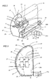
- the machine 1 further comprises means, denoted 23, by which to deliver a flow "F” of air circulating internally of the enclosing chamber 14 and around the feed path "P".
- the webs or strips 5 of filter material advancing through the enclosing chamber 14 are not invested by the flow "F" of air, which circles around the webs or strips 5, remaining tangential to the internal wall 24.
- the internal wall 24, also substantially tubular in appearance, is composed of a lower portion 25 and an upper portion 26.
- the two portions 25 and 26 each present a cross sectional profile substantially of "U" outline, creating respective concave faces 25a and 26a directed one toward another and both toward the continuous web or strip 5 of filter material
- Each portion 25 and 26 also presents respective corner areas 27 of coved profile serving to ensure that the air flow "F" does not become detached from the internal wall 24 at these same corner areas 27.
- the coved corner areas 27 having a particularly accentuated curvature are fitted with deflectors 27a that help to guide the flow of air smoothly along the internal wall 24.
- the enclosing chamber 14 is of a type that can be opened so as to allow inspection or servicing inside when necessary, as discernible in figure 4, which shows an access door 14b that can be opened by rotation on a hinge axis denoted C (indicated by a point in the view of figure 4).
- the rounded profile of the coved corner areas 27 is instrumental in maintaining a laminar flow "F" of air and avoiding localized pockets of turbulence or stagnation that could affect the webs or strips 5 of filter material.
- the lower portion 25 and the upper portion 26 are interfaced separably and in such a way that an operator can remove the upper portion 26 to access the inside of the chamber 14. Moreover, the two portions 25 and 26 combine to create a rectilinear segment 28 placed transversely to the longitudinal plane occupied by the webs or strips 5 of material and extending alongside.
- a box 29 Positioned in close proximity to the lower portion 25 is a box 29 extending along the aforementioned rectilinear segment 28, preferably below the level of the webs or strips 5.
- the box 29 extends along the full length of the chamber 14 and presents a rectangular cross sectional profile of which a first surface 29a extends transversely to the rectilinear segment 28.
- the surface 29a in question creates a deflecting channel placed in the path of the air flow entering the chamber 14.
- the air is directed into the chamber 14 by the deflecting channel along a direction such that the flow will skim the rectilinear segment 28, with no draught projected toward the middle of the chamber 14.
- the delivery means 23 producing the flow "F" of air comprise a motor 29b connected to the box 29 and driving a rotor (not indicated in the drawings) housed in the selfsame box 29.
- the rotor In operation, the rotor generates an airstream passing through an outlet vent 30 presented by the first surface 29a mentioned previously, and associated with the deflector channel (see figures 5 and 6).
- the outlet vent 30 extending the full length of the chamber 14 as aforementioned, parallel to the webs or strips 5 of filter material, the airstream can be directed parallel with and across the entire expanse of the rectilinear segment 28.
- the delivery means 23 further comprise an inlet vent 31 afforded by the rectilinear segment 28, below the level of the box 29, also extending the full length of the chamber 14.
- the inlet vent 31 is associated with a vacuum pump denoted 31a, conventional in embodiment and therefore not described in detail.
- the inlet vent 31 is positioned substantially perpendicular to the direction of the air flow (see figure 4 and 6), so that the flow of air can be extracted without being diverted from its path "A".
- the inlet vent 31 comprises a ducting baffle 31b and a dividing baffle 31c designed to ensure that the flow of air exiting the chamber 14 cannot collide with the flow of air entering the chamber 14 (see figures 4 and 6).
- the inlet vent 31 might also be associated with a collection vessel (also conventional, and therefore not illustrated) into which volatile particles entrained and transported by the flow "F" can be directed.
- the flow "F" described above and illustrated in the drawings will consist preferably in a flow of air ionized by an electrical conductor in familiar manner, so that volatile particles of tow shed during the passage of the webs or strips 5 of filter material through the enclosing chamber 14 will be more easily attracted and retained.
- the flow "F" of air serves to remove the particles in question, and to prevent them from infiltrating the chemical treatment station 15 by way of the openings 17 in the dividing baffle 16.
- the feed motion of the continuous webs or strips 5 of filter material is unaffected by the flow "F" of air, with the flow generated as a tubular loop encircling the selfsame webs 5.
- the advantage derives from the fact that the flow is laminar, and follows the profile of the internal wall 24 without creating pockets of turbulence or stagnation by which the webs 5 could be affected.
Landscapes
- Engineering & Computer Science (AREA)
- Manufacturing & Machinery (AREA)
- Cigarettes, Filters, And Manufacturing Of Filters (AREA)
- Manufacturing Of Cigar And Cigarette Tobacco (AREA)
Applications Claiming Priority (1)
| Application Number | Priority Date | Filing Date | Title |
|---|---|---|---|
| ITBO20060647 ITBO20060647A1 (it) | 2006-09-20 | 2006-09-20 | Macchina per la produzione di filtri di sigarette. |
Publications (2)
| Publication Number | Publication Date |
|---|---|
| EP1902634A2 true EP1902634A2 (fr) | 2008-03-26 |
| EP1902634A3 EP1902634A3 (fr) | 2009-12-23 |
Family
ID=38828638
Family Applications (1)
| Application Number | Title | Priority Date | Filing Date |
|---|---|---|---|
| EP07116468A Withdrawn EP1902634A3 (fr) | 2006-09-20 | 2007-09-14 | Machine pour fabrication de filtres de cigarette |
Country Status (2)
| Country | Link |
|---|---|
| EP (1) | EP1902634A3 (fr) |
| IT (1) | ITBO20060647A1 (fr) |
Cited By (1)
| Publication number | Priority date | Publication date | Assignee | Title |
|---|---|---|---|---|
| EP2106709A1 (fr) * | 2008-04-01 | 2009-10-07 | Hauni Maschinenbau AG | Dispositif de transport d'un cordon filtrant |
Family Cites Families (3)
| Publication number | Priority date | Publication date | Assignee | Title |
|---|---|---|---|---|
| US2954036A (en) * | 1958-06-03 | 1960-09-27 | Olin Mathieson | Cellulosic sheet and filter, and process therefor |
| DE19811014A1 (de) * | 1998-03-13 | 1999-09-16 | Hauni Maschinenbau Ag | Verfahren und Vorrichtung zum Herstellen von Filterstäben für stabförmige Artikel der tabakverarbeitenden Industrie |
| DE10123351B4 (de) * | 2001-05-14 | 2005-02-03 | Rhodia Acetow Gmbh | Verfahren und Vorrichtung zur Herstellung von Zigarettenfiltern |
-
2006
- 2006-09-20 IT ITBO20060647 patent/ITBO20060647A1/it unknown
-
2007
- 2007-09-14 EP EP07116468A patent/EP1902634A3/fr not_active Withdrawn
Cited By (1)
| Publication number | Priority date | Publication date | Assignee | Title |
|---|---|---|---|---|
| EP2106709A1 (fr) * | 2008-04-01 | 2009-10-07 | Hauni Maschinenbau AG | Dispositif de transport d'un cordon filtrant |
Also Published As
| Publication number | Publication date |
|---|---|
| ITBO20060647A1 (it) | 2006-12-20 |
| EP1902634A3 (fr) | 2009-12-23 |
Similar Documents
| Publication | Publication Date | Title |
|---|---|---|
| US3019793A (en) | Cigarette-making machines of the continuous rod type | |
| US3010576A (en) | Apparatus for separating or winnowing tobacco and other like fibrous material | |
| EP1364588B1 (fr) | Dispositif et procédé pour la formation d'au moins deux tiges de tabac dans une machine de fabrication de tige de tabac | |
| DE2623547A1 (de) | Vorrichtung zum bilden eines tabakstranges | |
| PL188570B1 (pl) | Sposób i urządzenie do wytwarzania filtrów dla prętopodobnych artykułów przemysłu tytoniowego | |
| RU2751950C1 (ru) | Установка для обработки бумаги | |
| US5267576A (en) | Method of and apparatus for separating foreign objects from moving tobacco particles in a rod making machine | |
| CN101991188B (zh) | 用于处理条状烟草制品废料的装置 | |
| US3095883A (en) | Continuous rod cigarette-making machines | |
| EP1902634A2 (fr) | Machine pour fabrication de filtres de cigarette | |
| IT9021739A1 (it) | Procedimento e dispositivo per produrre un filone di tabacco | |
| DE10132760A1 (de) | Vorrichtung zur Vorbereitung eines Faserstranges der tabakverarbeitenden Industrie | |
| US6334243B1 (en) | Method of and apparatus for manipulating tows of filter material for tobacco smoke | |
| US6814080B2 (en) | Apparatus for making a tobacco rod | |
| JP2840302B2 (ja) | 紙巻タバコ製造機並びに紙巻タバコを製造する方法 | |
| KR101853778B1 (ko) | 토우 절단기 | |
| EP1825767B1 (fr) | Corps d'écoulement d'une machine à rouler des cigarettes | |
| EP1325685B1 (fr) | Dispositif et procédé pour le traitement d'une bande de matière filtrante pour l'industrie du tabac | |
| US4041958A (en) | Apparatus for producing a continuous tobacco stream | |
| US3613692A (en) | Apparatus for building a continuous tobacco stream | |
| JP2527772B2 (ja) | たばこ加工産業におけるシガレット連続体製造機のための空気案内機構 | |
| US5154190A (en) | Apparatus for building a tobacco stream | |
| JP3910109B2 (ja) | 巻上機の刻たばこ給送装置 | |
| EP0412446B1 (fr) | Procédé pour influencer le conditionnement des fibres traitées sur machine de filature | |
| US3291137A (en) | Tobacco manipulating machinery |
Legal Events
| Date | Code | Title | Description |
|---|---|---|---|
| PUAI | Public reference made under article 153(3) epc to a published international application that has entered the european phase |
Free format text: ORIGINAL CODE: 0009012 |
|
| AK | Designated contracting states |
Kind code of ref document: A2 Designated state(s): AT BE BG CH CY CZ DE DK EE ES FI FR GB GR HU IE IS IT LI LT LU LV MC MT NL PL PT RO SE SI SK TR |
|
| AX | Request for extension of the european patent |
Extension state: AL BA HR MK YU |
|
| PUAL | Search report despatched |
Free format text: ORIGINAL CODE: 0009013 |
|
| AK | Designated contracting states |
Kind code of ref document: A3 Designated state(s): AT BE BG CH CY CZ DE DK EE ES FI FR GB GR HU IE IS IT LI LT LU LV MC MT NL PL PT RO SE SI SK TR |
|
| AX | Request for extension of the european patent |
Extension state: AL BA HR MK RS |
|
| 17P | Request for examination filed |
Effective date: 20100204 |
|
| AKX | Designation fees paid |
Designated state(s): AT BE BG CH CY CZ DE DK EE ES FI FR GB GR HU IE IS IT LI LT LU LV MC MT NL PL PT RO SE SI SK TR |
|
| STAA | Information on the status of an ep patent application or granted ep patent |
Free format text: STATUS: THE APPLICATION IS DEEMED TO BE WITHDRAWN |
|
| 18D | Application deemed to be withdrawn |
Effective date: 20120403 |