EP1902647B1 - Anlage zum ermöglichen des anschlusses von zwei menüwagen an einen festanschluss - Google Patents
Anlage zum ermöglichen des anschlusses von zwei menüwagen an einen festanschluss Download PDFInfo
- Publication number
- EP1902647B1 EP1902647B1 EP07116991.6A EP07116991A EP1902647B1 EP 1902647 B1 EP1902647 B1 EP 1902647B1 EP 07116991 A EP07116991 A EP 07116991A EP 1902647 B1 EP1902647 B1 EP 1902647B1
- Authority
- EP
- European Patent Office
- Prior art keywords
- fixed terminal
- mouths
- mouth
- cold
- cart
- Prior art date
- Legal status (The legal status is an assumption and is not a legal conclusion. Google has not performed a legal analysis and makes no representation as to the accuracy of the status listed.)
- Active
Links
Images


Classifications
-
- A—HUMAN NECESSITIES
- A47—FURNITURE; DOMESTIC ARTICLES OR APPLIANCES; COFFEE MILLS; SPICE MILLS; SUCTION CLEANERS IN GENERAL
- A47J—KITCHEN EQUIPMENT; COFFEE MILLS; SPICE MILLS; APPARATUS FOR MAKING BEVERAGES
- A47J39/00—Heat-insulated warming chambers; Cupboards with heating arrangements for warming kitchen utensils
- A47J39/006—Heat-insulated warming chambers; Cupboards with heating arrangements for warming kitchen utensils for either storing and preparing or for preparing food on serving trays, e.g. heating, thawing, preserving
-
- B—PERFORMING OPERATIONS; TRANSPORTING
- B64—AIRCRAFT; AVIATION; COSMONAUTICS
- B64D—EQUIPMENT FOR FITTING IN OR TO AIRCRAFT; FLIGHT SUITS; PARACHUTES; ARRANGEMENT OR MOUNTING OF POWER PLANTS OR PROPULSION TRANSMISSIONS IN AIRCRAFT
- B64D13/00—Arrangements or adaptations of air-treatment apparatus for aircraft crew or passengers, or freight space
- B64D13/06—Arrangements or adaptations of air-treatment apparatus for aircraft crew or passengers, or freight space the air being conditioned
- B64D2013/0603—Environmental Control Systems
- B64D2013/0629—Environmental Control Systems with subsystems for cooling food, catering or special loads
Definitions
- the present invention relates to the technical field of transport and distribution of meals using trays on which are placed dishes and various utensils necessary for the consumption of food.
- the object of the invention finds a particularly advantageous application in the field of transport and distribution of meals for example in a hospital environment.
- a meal tray is intended to receive cold and hot dishes placed in containers adapted to the nature of the food.
- the hot dishes are, as soon as they are prepared, conveyed and kept at the consumption temperature until they are distributed to the consumer.
- the hot dishes are put to the temperature of consumption just before their distribution to the consumer insofar as they have been rapidly cooled as soon as they have been prepared for cold storage up to several times. days.
- Such a transport and distribution trolley comprises, for example as illustrated by the patent US 3,275,393 , two separate compartments, one of which is intended to receive the trays provided with the utensils and cold dishes, while the other receives the containers containing the hot dishes.
- the so-called hot compartment is equipped with heating means to place and maintain the food at their consumption temperature.
- the so-called cold compartment is connected to an on-board refrigeration unit generally comprising a compressor unit, a condenser and an evaporator.
- This solution has the disadvantage of providing particularly bulky, heavy and expensive trolleys especially because of the assembly of a cold production unit inside each trolley.
- the patent application EP 0 161 178 has proposed an installation with a fixed hot and cold production terminal and on which is intended to be connected at least one isothermal trolley for the transport and distribution of meals.
- the fixed terminal has a compartment including a source of cold air capable of pulsing the air inside a lower compartment of the said cold carriage when the latter is attached to the production terminal.
- the lower compartment which opens on one side of the carriage is separated by a horizontal partition, an upper compartment in which can be pulsed hot air from the fixed terminal.
- the horizontal partition is provided with an opening closable by a register regulating the communication between the lower and upper compartments to allow the implementation of single or double refrigeration modes. Indeed, in some cases of use, it is necessary to implement a simple refrigeration consisting of connecting to the cold source only the cold compartment. In this case, the hot compartment is not connected to the cold source prior to its connection to the hot source.
- the present invention therefore aims to remedy the drawbacks set forth above by proposing an installation adapted to allow the cold keeping of dishes placed on meal trays, designed to be inexpensive while offering the possibility of allowing automatic regulation of the food. temperature inside the trolleys.
- the fixed terminal comprises, on each of the two parallel walls, a cold air blowing mouth and an air suction mouth.
- Each carriage has an air intake port communicating with a sheath with the cold compartment which communicates by a sheath with the air outlet mouth.
- the fixed terminal comprises, for each of the temporary coupling means, a means for detecting the presence of a trolley, adapted to allow the automatic piloting of the trolley. operation of complementary temporary coupling means when detecting a carriage in position to be locked with the fixed terminal.
- the fixed terminal comprises closure plugs of the blow and suction mouths and shutter doors of the inlet and outlet mouths.
- the means for reheating the meal trays are made by heating plates of the induction type or electrical resistance.
- the blow and suction mouths are located in a central symmetry arrangement with respect to the plane of symmetry parallel to the parallel walls extending in opposite manner, while the inlet and outlet mouths are offset relative to the middle of the carriage so as to allow their connection respectively the blow and suction mouths of one or the other of the walls of the fixed terminal.
- blow and suction mouths are located in an arrangement of axial symmetry with respect to the plane of symmetry parallel to the side walls.
- the two parallel walls are mounted next to each other.
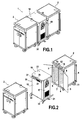
- each carriage 2 comprises an insulated envelope 3 delimiting at least one enclosure 4 accessible by at least one and in the example illustrated by a double set of two doors 5.
- the enclosure 4 opens according to two opposite sides of the carriage namely the front and rear faces each equipped with two doors 5.
- the enclosure 4 is closed by two opposite side walls 6 disposed between the front and rear faces and connected by bottom and top walls.
- the chamber 4 has at least one so-called cold compartment 7 and in the example also illustrated a so-called hot compartment 8.
- the cold compartments 7 and 8 are separated by a vertical partition 9.
- the walls of the compartments 7, 8 are provided with various equipment and in particular support means for maintaining in superimposed position meal trays.
- the compartments 7, 8 are intended to receive the portions of the meal trays respectively supporting the cold and hot dishes and thus extending on either side of the partition wall 9.
- the partition of separation 9 may be provided with superimposed slots allowing the passage of meal trays.
- the hot compartment 8 is provided with food heating means placed in the hot compartment. These heating means are made by heating plates mounted superimposed on the inside of the compartment hot. Each plate is of the heating resistance or induction type.
- the carriage 2 is equipped with rolling means 11.
- Each carriage 2 is equipped on one of its faces, namely the front face in the illustrated example, of at least one air inlet mouth 12, and at least one air outlet mouth 13 communicating with the cold compartment 7 by sheaths 14 extending for example in the walls of the chamber or inside the cold compartment 7. It must be considered that each mouth 12, 13 is made by a punctiform opening or located in a face of the carriage 2. In the illustrated example, each mouth 12, 13 is arranged in an upper band of the front surface surmounting the doors 5.
- Each carriage 2 is provided with temporary coupling means 15 with a fixed terminal 16 adapted to at least cool or keep cold compartment 7.
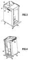
- the fixed terminal 16 is in the form of a parallelepiped structure having a front wall 17 extending parallel to a rear wall 18 and two side walls 19 parallel to each other and extending in the example shown in FIGS. Fig. 1 to 5 between the front and rear walls.
- the walls 17, 18 and 19 extend vertically and are supported by a base 21 extending parallel to a top wall 22.
- the side walls 19 extend opposite each other or opposite way.
- the fixed terminal 16 comprises a refrigerating unit 24 of any type known per se.
- the refrigerating unit 24 comprises a refrigerant circuit associated with an evaporator and a condenser and with ventilation means.
- the refrigerating unit 24 is able to create a cold air circulation circuit comprising ducts 26 ensuring the supply of cold air from the refrigerating unit 24 to two cold air supply vents 27 and the return of air from two suction ports 28 to the refrigeration unit 24.
- each side wall 19 is equipped with a cold air blower 27 and an air intake port 28 complementary respectively to the air inlet port 12 and the air outlet mouth 13 of a carriage.
- an air inlet mouth 12 cooperates with a cold air supply mouth 27 while an outlet mouth of air 13 cooperates with the suction mouth 28.
- the cold air coming from the refrigerating unit 24 is conveyed into the cold compartment 7 via a pipe 26, a blowing mouth 27, an air inlet mouth 12, a sheath 14 and returns to the refrigerating unit 24 via a feed sheath 14, an outlet mouth 13, a suction mouth 28 and a pipe 26.
- blowing 27 and suction mouths 28, and the inlet mouths 12 and outlet 13 are adapted to ensure good airtightness.
- These mouths 27 and 28, 12 and 13 point or localized character can thus be provided with nozzles, nozzles and / or seals of any type or have complementary forms of interlocking.
- the position of the mouths 12, 13, 27 and 28 is selected so as to obtain co-operation between on the one hand, the inlet mouths 12 and blower 27 and between the output ducts 13 and suction 28 side on the other hand, simply by bringing a carriage 2 into contact with the fixed terminal 16.
- the blowing 27 and suction mouths 28 are located in an arrangement of central symmetry with respect to the plane of symmetry parallel to the side walls 19.
- the inlet mouths 12 and outlet 13 are offset relative to the medium of the cart.
- the offset of the blowing 27 and suction mouths 28, in a direction opposite to one wall to another allows the connection indifferently on one or the other of its faces, a carriage having the same lateral offset for the inlet mouths 12 and outlet 13. All the carriages 2 thus have the same provision for the inlet mouths 12 and outlet 13 which can thus be indifferently connected to the one or the other of the faces of the fixed terminal 16.
- the fixed terminal 16 comprises the temporary coupling means 31 complementary to the temporary coupling means 15 of a carriage for maintaining the carriage in a fixed position of coupling in which the mouths blowing 27 and suction 28 are respectively sealed connection with the inlet mouths 12 and outlet 13.
- Each side face 19 is equipped with temporary coupling means 31 which are of course positioned according to provision of a central symmetry as described above in relation of intake vents 12 and outlet 13.
- the means for temporarily coupling to a carriage 15 which are offset are designed to cooperate indifferently with means Coupling 31 of one or other of the faces 19 of the fixed terminal 16.
- the temporary coupling means 15, 31 are made by an electromagnetic suction pad.
- the fixed terminal 16 comprises for each temporary coupling means 31, a not shown means for detecting the presence of a carriage 2.
- the electromagnetic pad is activated when the means detects the presence of a carriage placed in a position to be locked with the fixed terminal, that is to say corresponding to the connection between the mouths.
- a detection means is an optical or proximity sensor.
- the fixed terminal 16 is equipped at its base 21, guides 32 facilitating the supply and positioning of the carriage in its contact or locking position with the fixed terminal 16.
- the fixed terminal 16 also comprises a control and regulation unit 40 for controlling the operation of the fixed terminal.
- This control and regulation unit 40 comprises a control interface located on the front wall 17 of the fixed terminal 16. This control and regulation unit 40 makes it possible to ensure the proper operation of the installation which flows directly from the above description.
- the temporary coupling means When a sensor detects the presence of a carriage, the temporary coupling means are activated to firmly anchor the carriage to the fixed terminal. In this position, the cold compartment 7 is connected to the refrigeration unit 24 which is then controlled to ensure the circulation of cold air in the cold compartment 7.
- the control and regulation unit 40 thus allows to maintain for a determined duration a determined temperature inside the cold compartment 7. It should be noted that the control and regulation unit 40 controls the operation of the electric heating means of the hot compartment 8.
- the carriage 2 is connected to the fixed terminal 16 by a not shown electrical connection cable.
- the fixed terminal 16 can operate when it is connected to one or two carriages 2.
- the fixed terminal 16 has a priority connection face.
- a sealing mouth 42 is placed on the intake openings 27 and suction 28 which are situated on the non-focal side of the fixed terminal 16.
- the fixed terminal 16 delimits, by each side wall 19, a reception space for a carriage 2 whose front or connecting face has dimensions substantially identical to the side wall 19.
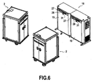
- the Fig. 6 illustrates another embodiment of the fixed terminal 16 illustrated in FIGS. Fig. 1 to 5 .
- the two side walls 19 are placed next to each other to form a common connection face for the carriages.
- the two walls 19 thus extend parallel to each other and in the extension of one another in the illustrated example.
- the two carriages 2 are thus placed side by side when they are connected to the fixed terminal 16.
- the fixed terminal 16 according to this embodiment remains identical to the description of the fixed terminal 16 performed above.
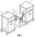
- the Fig. 7 and 8 illustrate another alternative embodiment for implementing more precisely a so-called double refrigeration operating mode.
- the hot compartment 8 is said to be mixed insofar as this compartment is first cooled simultaneously to the cold compartment 7.
- the cooling of the hot compartment is stopped and the heating or reheating means are controlled in operation.
- the fixed terminal 16 has on each of its two opposite walls 19, two air-blowing mouths 27 and two air-intake mouths 28 communicating via ducts 26 with the refrigerating unit 24 as described above.
- each carriage 2 comprises two air inlet mouths 12 , one of which communicates via a sheath 14 with the cold compartment 7 which communicates by a sheath 14 with an outlet mouth 13.
- the other air inlet 12 communicates by a sheath 14 with the mixed compartment 8 which communicates by a sheath 14 with the other outlet mouth 13.
- these inlet mouths 12 and outlet 13 are arranged on a side wall 6 of the carriage.
- the air inlet vents 12 are located at the same level above the two exhaust openings 13.
- the intake openings 27 and suction 28 are located in a symmetrical arrangement axial to the plane of symmetry parallel to the side walls 19 of the fixed terminal 16. The two mouths 27 are therefore located side by side superimposed on the suction mouths 28.
- Each carriage 2 is provided with temporary coupling means 15 arranged centrally on the wall 6 in which the mouths 12 and 13 are arranged .
- the temporary coupling means 31 are arranged centrally on each of the walls 19 of the fixed terminal 16.
- the refrigerating unit 24 it first appears necessary for the refrigerating unit 24 to cool both the cold compartment 7 and the mixed compartment 8.
- the refrigerating unit 24 must not feed in cold air the mixed compartment 8 when the heating means are activated.
- closure means 45 such as controlled flaps are mounted on the pipes 26 so that the blowing 27 and suction 28 mouths do not deliver cold air.
- the carriage 2 comprises a cold compartment 7 and a mixed compartment 8.
- the object of the invention can be implemented for a carriage 2 comprising only a cold compartment 7.
- the Fig. 9 illustrates another embodiment of the fixed terminal illustrated in FIGS. Fig. 7 and 8 and concerning the so-called double refrigeration mode of operation.
- the two side walls 19 are placed next to each other to form a common connection face for the carriages.
- the two walls 19 thus extend parallel to each other and in the extension of each other in the illustrated example.
- the two carriages 2 are thus placed side by side when they are connected to the fixed terminal 16.
Landscapes
- Engineering & Computer Science (AREA)
- Food Science & Technology (AREA)
- Devices That Are Associated With Refrigeration Equipment (AREA)
- Cold Air Circulating Systems And Constructional Details In Refrigerators (AREA)
Claims (10)
- Anlage mindestens zum Kühlhalten von Speisen, die auf Esstabletts angeordnet sind, umfassend :- mindestens zwei isotherme Wagen (2) zur Beförderung von Esstabletts, jeweils umfassend :* eine Isolierhülle (3), die mindestens einen Raum (4) begrenzt, der durch mindestens eine Tür (5) zugänglich ist und mindestens ein kaltes Abteil (7) aufweist, wobei dieser Raum innen mit Mitteln zum Tragen von Esstabletts in übereinander angeordneter Position versehen ist;- eine feste Klemme (16), umfassend eine Kühleinheit (24) und eine Einheit (40) zur Steuerung und Einstellung der Kälte, dadurch gekennzeichnet, dass :- jeder Wagen auf einer seiner Seiten versehen ist mit:* mindestens einer Lufteinlassöffnung (12) und mindestens einer Luftauslassöffnung (13), die durch Stutzen (14) mit dem kalten Abteil in Verbindung stehen ;* und Mitteln zur vorübergehenden Kopplung (15) mit der festen Klemme (16);- wobei die feste Klemme (16) zwei Seitenwände (19) umfasst, die jeweils ausgestattet sind mit:* mindestens einer Kaltlufteinblasöffnung (27), die zu der Lufteinlassöffnung eines Wagens komplementär ist, um mit ihr bei der Kopplung eines Wagens mit der festen Klemme zusammenzuwirken, wobei die Blasöffnungen (27) durch Kanalisationen (26) mit der Kühleinheit (24) in Verbindung stehen ;* mindestens einer Luftansaugöffnung (28), die zu der Luftauslassöffnung eines Wagens komplementär ist, um mit dieser bei der Kopplung eines Wagens mit der festen Klemme zusammenzuwirken, wobei die Luftansaugöffnungen (28) durch Kanalisationen (26) mit der Kühleinheit (24) in Verbindung stehen ;* vorübergehende Kopplungsmittel (31), die zu den vorübergehenden Kopplungsmitteln (15) eines Wagens komplementär sind, um das Halten eines Wagens in einer festen Kopplungsposition, in der die Blas- (27) und Ansaugöffnungen (28) dicht an die Einlass- (12) bzw. Auslassöffnungen (13) angeschlossen sind, zu gewährleisten ;- wobei die Einheit zur Steuerung und Einstellung (40) die Steuerung und die Einstellung für den einen und/oder den anderen der Wagen, die an die feste Klemme gekoppelt sind, gewährleistet.
- Anlage nach Anspruch 1, dadurch gekennzeichnet, dass jeder Wagen (2) umfasst:- einen Raum, der das kalte Abteil (7) und ein gemischtes Abteil (8) kalt oder warm aufweist;- Mittel zum Aufwärmen der Esstabletts für das gemischte Abteil (8).
- Anlage nach Anspruch 1 oder 2, dadurch gekennzeichnet, dass :- die feste Klemme (16) auf jeder ihrer beiden parallelen Wände (19) eine Kaltluftblasöffnung (27) und eine Luftansaugöffnung (28) umfasst;- jeder Wagen eine Lufteinlassöffnung (12) umfasst, die durch einen Stutzen mit dem kalten Abteil (7) in Verbindung steht, das durch einen Stutzen (14) mit der Luftauslassöffnung (13) in Verbindung steht.
- Anlage nach Anspruch 2, dadurch gekennzeichnet, dass :- die feste Klemme (16) umfasst:* auf jeder der beiden parallelen Wände (19) zwei Kaltluftblasöffnungen (27) und zwei Luftansaugöffnungen (28);* Mittel (45) für den gesteuerten Verschluss einer Blasöffnung (27) und einer Ansaugöffnung (28), die dazu bestimmt sind, mit dem gemischten Abteil des Wagens in Verbindung zu stehen ;- jeder Wagen (2) zwei Lufteinlassöffnungen (12) umfasst, von denen eine durch einen Stutzen (24) mit dem kalten Abteil (7) verbunden ist, das durch einen stützen mit einer Luftauslassöffnung (13) in Verbindung steht, wobei die andere Lufteinlassöffnung (12) durch einen Stutzen (24) mit dem gemischten Abteil verbunden ist, das durch einen Stutzen mit der anderen Luftauslassöffnung (13) in Verbindung steht.
- Anlage nach einem der Ansprüche 1 bis 4, dadurch gekennzeichnet, dass die feste Klemme (16) für jedes der Mittel zur vorübergehenden Kopplung (31) ein Mittel zur Erfassung des Vorhandenseins eines Wagens umfasst, das dazu vorgesehen ist, es zu ermöglichen, automatisch die Funktion der Mittel zur komplementären vorübergehenden Kopplung bei der Erfassung eines Wagens in einer Position, um mit der festen Klemme verriegelt zu werden, zu steuern.
- Anlage nach einem der Ansprüche 1 bis 5, dadurch gekennzeichnet, dass sie Verschlussstöpsel (42) der Blas- (27) und Ansaugöffnungen (28) und Verschlussklappen der Einlass- und Auslassöffnungen umfasst.
- Anlage nach Anspruch 2, dadurch gekennzeichnet, dass die Mittel zum Aufwärmen der Esstabletts Heizplatten mit Induktion oder elektrischem Widerstand sind.
- Anlage nach Anspruch 3, dadurch gekennzeichnet, dass die Blas- (27) und Ansaugöffnungen (28) in einer zentralen symmetrischen Anordnung in Bezug zur Symmetrieebene parallel zu den parallelen Wänden (19), die sich entgegengesetzt erstrecken, angeordnet sind, während die Einlass- (12) und Auslassöffnungen (13) in Bezug zur Mitte des Wagens versetzt sind, um den Anschluss der Blas- (27) bzw. Ansaugöffnungen (28) der einen oder der anderen der Wände der festen Klemme zu ermöglichen.
- Anlage nach Anspruch 4, dadurch gekennzeichnet, dass die Blas- (27) und Ansaugöffnungen (28) in einer Anordnung axialer Symmetrie in Bezug zur Symmetrieebene parallel zu den Seitenwänden (19) angeordnet sind.
- Anlage nach einem der Ansprüche 1 bis 4, dadurch gekennzeichnet, dass die beiden parallelen Wände (19) nebeneinander montiert sind.
Applications Claiming Priority (1)
| Application Number | Priority Date | Filing Date | Title |
|---|---|---|---|
| FR0653909A FR2906121B1 (fr) | 2006-09-22 | 2006-09-22 | Installation pour permettre le raccordement a une borne fixe de deux chariots de transport de plateaux-repas |
Publications (2)
| Publication Number | Publication Date |
|---|---|
| EP1902647A1 EP1902647A1 (de) | 2008-03-26 |
| EP1902647B1 true EP1902647B1 (de) | 2016-11-09 |
Family
ID=38007340
Family Applications (1)
| Application Number | Title | Priority Date | Filing Date |
|---|---|---|---|
| EP07116991.6A Active EP1902647B1 (de) | 2006-09-22 | 2007-09-21 | Anlage zum ermöglichen des anschlusses von zwei menüwagen an einen festanschluss |
Country Status (2)
| Country | Link |
|---|---|
| EP (1) | EP1902647B1 (de) |
| FR (1) | FR2906121B1 (de) |
Cited By (1)
| Publication number | Priority date | Publication date | Assignee | Title |
|---|---|---|---|---|
| US11730263B2 (en) | 2021-07-02 | 2023-08-22 | Regethermic Canada Inc. | System for storing and delivering food trays |
Families Citing this family (6)
| Publication number | Priority date | Publication date | Assignee | Title |
|---|---|---|---|---|
| US9676483B2 (en) * | 2013-07-03 | 2017-06-13 | B/E Aerospace, Inc. | Aircraft galley air chiller system |
| US9986822B2 (en) * | 2014-05-01 | 2018-06-05 | The Boeing Company | Method and apparatus for cooling an airline galley cart using a skin heat exchanger |
| DE102015102885A1 (de) * | 2015-02-27 | 2016-09-01 | Airbus Operations Gmbh | System zum Herstellen einer Küchenanordnung für eine Kabine eines Fahrzeugs mit einem Hauptmodul und daran anbringbaren Zusatzmodulen, eine Küchenanordnung und ein Flugzeug mit einer solchen Küchenanordnung |
| CN106499486A (zh) * | 2016-12-27 | 2017-03-15 | 重庆钜云机电有限公司 | 摩托车用加热保温装置 |
| KR102300199B1 (ko) * | 2019-12-18 | 2021-09-10 | (주)엔에스제이 | 배식판 반납카 |
| CN113289977B (zh) * | 2021-06-21 | 2024-02-06 | 天津瑞能电气有限公司 | 一种应用于狭小空间的异物清洁装置 |
Family Cites Families (3)
| Publication number | Priority date | Publication date | Assignee | Title |
|---|---|---|---|---|
| FR2562783B1 (fr) * | 1984-04-17 | 1987-08-28 | Hervieu Michel | Ensemble de chariots et de bornes de mise en temperature en particulier pour service de repas collectifs |
| EP0848800B1 (de) * | 1995-09-08 | 2000-12-13 | René Grandi | Bewegbarer karren für warme und kalte fertiggericht-tabletts mit mitteln zur erwärmung und kühlung |
| US6832504B1 (en) * | 2003-11-19 | 2004-12-21 | Be Intellectual Property, Inc. | Liquid sensing system for an aircraft galley cooler using a two phase working fluid |
-
2006
- 2006-09-22 FR FR0653909A patent/FR2906121B1/fr active Active
-
2007
- 2007-09-21 EP EP07116991.6A patent/EP1902647B1/de active Active
Cited By (1)
| Publication number | Priority date | Publication date | Assignee | Title |
|---|---|---|---|---|
| US11730263B2 (en) | 2021-07-02 | 2023-08-22 | Regethermic Canada Inc. | System for storing and delivering food trays |
Also Published As
| Publication number | Publication date |
|---|---|
| FR2906121A1 (fr) | 2008-03-28 |
| EP1902647A1 (de) | 2008-03-26 |
| FR2906121B1 (fr) | 2009-01-09 |
Similar Documents
| Publication | Publication Date | Title |
|---|---|---|
| EP1902647A1 (de) | Anlage zum Ermöglichen des Anschlusses von zwei Menüwagen an einen Festanschluss | |
| EP0848800B1 (de) | Bewegbarer karren für warme und kalte fertiggericht-tabletts mit mitteln zur erwärmung und kühlung | |
| FR2502314A1 (fr) | Refrigerant a air en forme de panneau | |
| HUT72182A (en) | Cabinet-style apparatus for transferring heat to food and cooling food | |
| EP0583180B1 (de) | Kühlanlage für Tür eines Haushaltsbackofens | |
| EP2342065B1 (de) | Verbesserter ofen für die thermische konditionierung von aus einem thermoplastischen material hergestellten vorformlingen | |
| CA3166204C (en) | SYSTEM FOR STORING AND DISPENSING FOOD TRAYS | |
| EP1259146A1 (de) | Modulare einrichtung zum konservieren und zum aufwärmen von servierplatten | |
| JPS5878076A (ja) | 材料の冷却方法及び冷却容器 | |
| EP0968395B1 (de) | Gekühlter servierwagen | |
| EP0393061B1 (de) | Bewegliche gekühlte zelle für lebensmittel | |
| EP0161178A1 (de) | Fahrbare Muffelteile ankoppelbar an Wärme- und Kühleinheiten für Fertiggerichte | |
| EP3158267B1 (de) | Zuleitungsrohr für ofen | |
| FR2493667A1 (fr) | Dispositif de refroidissement pour installation contenant des equipements electroniques ou de telecommunications | |
| FR2954062A1 (fr) | Chariot de distribution de plateaux repas et procede de conditionnement de plateaux repas | |
| EP1775216B1 (de) | Selbstreinigender Wagen zum Transport und Verteilen von Essen auf Tabletts | |
| EP1584876B1 (de) | Speisetransportwagen mit doppelter, mitgeführter Kältereserve | |
| FR2735852A1 (fr) | Chariot isotherme et installation pour assurer le refroidissement de chariots isothermes | |
| FR2803653A1 (fr) | Dispositif pour le maintien au froid et la mise en temperature de plateaux-repas et installation mettant en oeuvre un tel dispositif | |
| FR3000362A1 (fr) | Bloc d'extraction d'air pour baie avionique | |
| FR2737000A1 (fr) | Installation pour assurer le refroidissement de chariots isothermes | |
| JPH0123100Y2 (de) | ||
| FR2883670A1 (fr) | Dispositif compact d'alimentation electrique pour un vehicule automobile | |
| FR2891354A1 (fr) | Receptacle de neige carbonique a double compartiment pour conteneurs isothermes | |
| FR2878236A1 (fr) | Chariot isotherme comportant des moyens mobiles embarques de production de froid |
Legal Events
| Date | Code | Title | Description |
|---|---|---|---|
| PUAI | Public reference made under article 153(3) epc to a published international application that has entered the european phase |
Free format text: ORIGINAL CODE: 0009012 |
|
| AK | Designated contracting states |
Kind code of ref document: A1 Designated state(s): AT BE BG CH CY CZ DE DK EE ES FI FR GB GR HU IE IS IT LI LT LU LV MC MT NL PL PT RO SE SI SK TR |
|
| AX | Request for extension of the european patent |
Extension state: AL BA HR MK YU |
|
| RIN1 | Information on inventor provided before grant (corrected) |
Inventor name: BROSSAT, PIERRE |
|
| 17P | Request for examination filed |
Effective date: 20080926 |
|
| 17Q | First examination report despatched |
Effective date: 20081030 |
|
| AKX | Designation fees paid |
Designated state(s): AT BE BG CH CY CZ DE DK EE ES FI FR GB GR HU IE IS IT LI LT LU LV MC MT NL PL PT RO SE SI SK TR |
|
| GRAP | Despatch of communication of intention to grant a patent |
Free format text: ORIGINAL CODE: EPIDOSNIGR1 |
|
| INTG | Intention to grant announced |
Effective date: 20160610 |
|
| GRAS | Grant fee paid |
Free format text: ORIGINAL CODE: EPIDOSNIGR3 |
|
| GRAA | (expected) grant |
Free format text: ORIGINAL CODE: 0009210 |
|
| AK | Designated contracting states |
Kind code of ref document: B1 Designated state(s): AT BE BG CH CY CZ DE DK EE ES FI FR GB GR HU IE IS IT LI LT LU LV MC MT NL PL PT RO SE SI SK TR |
|
| REG | Reference to a national code |
Ref country code: GB Ref legal event code: FG4D Free format text: NOT ENGLISH |
|
| REG | Reference to a national code |
Ref country code: AT Ref legal event code: REF Ref document number: 843071 Country of ref document: AT Kind code of ref document: T Effective date: 20161115 Ref country code: CH Ref legal event code: EP |
|
| REG | Reference to a national code |
Ref country code: IE Ref legal event code: FG4D Free format text: LANGUAGE OF EP DOCUMENT: FRENCH |
|
| REG | Reference to a national code |
Ref country code: DE Ref legal event code: R096 Ref document number: 602007048626 Country of ref document: DE |
|
| PG25 | Lapsed in a contracting state [announced via postgrant information from national office to epo] |
Ref country code: LV Free format text: LAPSE BECAUSE OF FAILURE TO SUBMIT A TRANSLATION OF THE DESCRIPTION OR TO PAY THE FEE WITHIN THE PRESCRIBED TIME-LIMIT Effective date: 20161109 |
|
| REG | Reference to a national code |
Ref country code: SE Ref legal event code: TRGR Ref country code: CH Ref legal event code: NV Representative=s name: BOVARD AG PATENT- UND MARKENANWAELTE, CH |
|
| REG | Reference to a national code |
Ref country code: LT Ref legal event code: MG4D |
|
| REG | Reference to a national code |
Ref country code: NL Ref legal event code: MP Effective date: 20161109 |
|
| PG25 | Lapsed in a contracting state [announced via postgrant information from national office to epo] |
Ref country code: NL Free format text: LAPSE BECAUSE OF FAILURE TO SUBMIT A TRANSLATION OF THE DESCRIPTION OR TO PAY THE FEE WITHIN THE PRESCRIBED TIME-LIMIT Effective date: 20161109 Ref country code: LT Free format text: LAPSE BECAUSE OF FAILURE TO SUBMIT A TRANSLATION OF THE DESCRIPTION OR TO PAY THE FEE WITHIN THE PRESCRIBED TIME-LIMIT Effective date: 20161109 Ref country code: GR Free format text: LAPSE BECAUSE OF FAILURE TO SUBMIT A TRANSLATION OF THE DESCRIPTION OR TO PAY THE FEE WITHIN THE PRESCRIBED TIME-LIMIT Effective date: 20170210 |
|
| PG25 | Lapsed in a contracting state [announced via postgrant information from national office to epo] |
Ref country code: PT Free format text: LAPSE BECAUSE OF FAILURE TO SUBMIT A TRANSLATION OF THE DESCRIPTION OR TO PAY THE FEE WITHIN THE PRESCRIBED TIME-LIMIT Effective date: 20170309 Ref country code: ES Free format text: LAPSE BECAUSE OF FAILURE TO SUBMIT A TRANSLATION OF THE DESCRIPTION OR TO PAY THE FEE WITHIN THE PRESCRIBED TIME-LIMIT Effective date: 20161109 Ref country code: IS Free format text: LAPSE BECAUSE OF FAILURE TO SUBMIT A TRANSLATION OF THE DESCRIPTION OR TO PAY THE FEE WITHIN THE PRESCRIBED TIME-LIMIT Effective date: 20170309 Ref country code: PL Free format text: LAPSE BECAUSE OF FAILURE TO SUBMIT A TRANSLATION OF THE DESCRIPTION OR TO PAY THE FEE WITHIN THE PRESCRIBED TIME-LIMIT Effective date: 20161109 Ref country code: FI Free format text: LAPSE BECAUSE OF FAILURE TO SUBMIT A TRANSLATION OF THE DESCRIPTION OR TO PAY THE FEE WITHIN THE PRESCRIBED TIME-LIMIT Effective date: 20161109 |
|
| PG25 | Lapsed in a contracting state [announced via postgrant information from national office to epo] |
Ref country code: SK Free format text: LAPSE BECAUSE OF FAILURE TO SUBMIT A TRANSLATION OF THE DESCRIPTION OR TO PAY THE FEE WITHIN THE PRESCRIBED TIME-LIMIT Effective date: 20161109 Ref country code: RO Free format text: LAPSE BECAUSE OF FAILURE TO SUBMIT A TRANSLATION OF THE DESCRIPTION OR TO PAY THE FEE WITHIN THE PRESCRIBED TIME-LIMIT Effective date: 20161109 Ref country code: DK Free format text: LAPSE BECAUSE OF FAILURE TO SUBMIT A TRANSLATION OF THE DESCRIPTION OR TO PAY THE FEE WITHIN THE PRESCRIBED TIME-LIMIT Effective date: 20161109 Ref country code: EE Free format text: LAPSE BECAUSE OF FAILURE TO SUBMIT A TRANSLATION OF THE DESCRIPTION OR TO PAY THE FEE WITHIN THE PRESCRIBED TIME-LIMIT Effective date: 20161109 |
|
| REG | Reference to a national code |
Ref country code: DE Ref legal event code: R097 Ref document number: 602007048626 Country of ref document: DE |
|
| PG25 | Lapsed in a contracting state [announced via postgrant information from national office to epo] |
Ref country code: BG Free format text: LAPSE BECAUSE OF FAILURE TO SUBMIT A TRANSLATION OF THE DESCRIPTION OR TO PAY THE FEE WITHIN THE PRESCRIBED TIME-LIMIT Effective date: 20170209 |
|
| PLBE | No opposition filed within time limit |
Free format text: ORIGINAL CODE: 0009261 |
|
| STAA | Information on the status of an ep patent application or granted ep patent |
Free format text: STATUS: NO OPPOSITION FILED WITHIN TIME LIMIT |
|
| REG | Reference to a national code |
Ref country code: FR Ref legal event code: PLFP Year of fee payment: 11 |
|
| 26N | No opposition filed |
Effective date: 20170810 |
|
| PG25 | Lapsed in a contracting state [announced via postgrant information from national office to epo] |
Ref country code: SI Free format text: LAPSE BECAUSE OF FAILURE TO SUBMIT A TRANSLATION OF THE DESCRIPTION OR TO PAY THE FEE WITHIN THE PRESCRIBED TIME-LIMIT Effective date: 20161109 |
|
| REG | Reference to a national code |
Ref country code: BE Ref legal event code: MM Effective date: 20170930 |
|
| PG25 | Lapsed in a contracting state [announced via postgrant information from national office to epo] |
Ref country code: BE Free format text: LAPSE BECAUSE OF NON-PAYMENT OF DUE FEES Effective date: 20170930 |
|
| REG | Reference to a national code |
Ref country code: FR Ref legal event code: PLFP Year of fee payment: 12 |
|
| PG25 | Lapsed in a contracting state [announced via postgrant information from national office to epo] |
Ref country code: MT Free format text: LAPSE BECAUSE OF FAILURE TO SUBMIT A TRANSLATION OF THE DESCRIPTION OR TO PAY THE FEE WITHIN THE PRESCRIBED TIME-LIMIT Effective date: 20161109 |
|
| PG25 | Lapsed in a contracting state [announced via postgrant information from national office to epo] |
Ref country code: HU Free format text: LAPSE BECAUSE OF FAILURE TO SUBMIT A TRANSLATION OF THE DESCRIPTION OR TO PAY THE FEE WITHIN THE PRESCRIBED TIME-LIMIT; INVALID AB INITIO Effective date: 20070921 |
|
| PG25 | Lapsed in a contracting state [announced via postgrant information from national office to epo] |
Ref country code: CY Free format text: LAPSE BECAUSE OF NON-PAYMENT OF DUE FEES Effective date: 20161109 |
|
| PG25 | Lapsed in a contracting state [announced via postgrant information from national office to epo] |
Ref country code: TR Free format text: LAPSE BECAUSE OF FAILURE TO SUBMIT A TRANSLATION OF THE DESCRIPTION OR TO PAY THE FEE WITHIN THE PRESCRIBED TIME-LIMIT Effective date: 20161109 |
|
| REG | Reference to a national code |
Ref country code: AT Ref legal event code: UEP Ref document number: 843071 Country of ref document: AT Kind code of ref document: T Effective date: 20161109 |
|
| REG | Reference to a national code |
Ref country code: DE Ref legal event code: R082 Ref document number: 602007048626 Country of ref document: DE Representative=s name: CBDL PATENTANWAELTE GBR, DE Ref country code: DE Ref legal event code: R082 Ref document number: 602007048626 Country of ref document: DE Representative=s name: CBDL PATENTANWAELTE EGBR, DE |
|
| PGFP | Annual fee paid to national office [announced via postgrant information from national office to epo] |
Ref country code: LU Payment date: 20250828 Year of fee payment: 19 |
|
| REG | Reference to a national code |
Ref country code: CH Ref legal event code: U11 Free format text: ST27 STATUS EVENT CODE: U-0-0-U10-U11 (AS PROVIDED BY THE NATIONAL OFFICE) Effective date: 20251001 |
|
| PGFP | Annual fee paid to national office [announced via postgrant information from national office to epo] |
Ref country code: DE Payment date: 20250916 Year of fee payment: 19 |
|
| PGFP | Annual fee paid to national office [announced via postgrant information from national office to epo] |
Ref country code: MC Payment date: 20250825 Year of fee payment: 19 |
|
| PGFP | Annual fee paid to national office [announced via postgrant information from national office to epo] |
Ref country code: IT Payment date: 20250910 Year of fee payment: 19 |
|
| PGFP | Annual fee paid to national office [announced via postgrant information from national office to epo] |
Ref country code: GB Payment date: 20250919 Year of fee payment: 19 |
|
| PGFP | Annual fee paid to national office [announced via postgrant information from national office to epo] |
Ref country code: FR Payment date: 20250918 Year of fee payment: 19 Ref country code: AT Payment date: 20250822 Year of fee payment: 19 |
|
| PGFP | Annual fee paid to national office [announced via postgrant information from national office to epo] |
Ref country code: SE Payment date: 20250925 Year of fee payment: 19 |
|
| PGFP | Annual fee paid to national office [announced via postgrant information from national office to epo] |
Ref country code: CZ Payment date: 20250829 Year of fee payment: 19 |
|
| PGFP | Annual fee paid to national office [announced via postgrant information from national office to epo] |
Ref country code: CH Payment date: 20251001 Year of fee payment: 19 |
|
| PGFP | Annual fee paid to national office [announced via postgrant information from national office to epo] |
Ref country code: IE Payment date: 20251031 Year of fee payment: 19 |