EP1902746A1 - Katheter-Aktuator - Google Patents
Katheter-Aktuator Download PDFInfo
- Publication number
- EP1902746A1 EP1902746A1 EP07253686A EP07253686A EP1902746A1 EP 1902746 A1 EP1902746 A1 EP 1902746A1 EP 07253686 A EP07253686 A EP 07253686A EP 07253686 A EP07253686 A EP 07253686A EP 1902746 A1 EP1902746 A1 EP 1902746A1
- Authority
- EP
- European Patent Office
- Prior art keywords
- catheter
- assembly
- carrier
- actuator
- catheter sheath
- Prior art date
- Legal status (The legal status is an assumption and is not a legal conclusion. Google has not performed a legal analysis and makes no representation as to the accuracy of the status listed.)
- Granted
Links
- 238000006073 displacement reaction Methods 0.000 claims abstract description 15
- 239000000969 carrier Substances 0.000 claims abstract description 14
- 230000000694 effects Effects 0.000 claims abstract description 5
- 230000015572 biosynthetic process Effects 0.000 claims description 10
- 230000003902 lesion Effects 0.000 description 6
- 238000010438 heat treatment Methods 0.000 description 4
- 238000002679 ablation Methods 0.000 description 3
- 230000006793 arrhythmia Effects 0.000 description 3
- 206010003119 arrhythmia Diseases 0.000 description 3
- 230000008901 benefit Effects 0.000 description 3
- 238000000034 method Methods 0.000 description 2
- 201000009273 Endometriosis Diseases 0.000 description 1
- 206010028980 Neoplasm Diseases 0.000 description 1
- 208000018737 Parkinson disease Diseases 0.000 description 1
- 238000005452 bending Methods 0.000 description 1
- 210000001124 body fluid Anatomy 0.000 description 1
- 230000002708 enhancing effect Effects 0.000 description 1
- 239000012530 fluid Substances 0.000 description 1
- 230000002262 irrigation Effects 0.000 description 1
- 238000003973 irrigation Methods 0.000 description 1
- 238000012986 modification Methods 0.000 description 1
- 230000004048 modification Effects 0.000 description 1
Images




Classifications
-
- A—HUMAN NECESSITIES
- A61—MEDICAL OR VETERINARY SCIENCE; HYGIENE
- A61M—DEVICES FOR INTRODUCING MEDIA INTO, OR ONTO, THE BODY; DEVICES FOR TRANSDUCING BODY MEDIA OR FOR TAKING MEDIA FROM THE BODY; DEVICES FOR PRODUCING OR ENDING SLEEP OR STUPOR
- A61M25/00—Catheters; Hollow probes
- A61M25/01—Introducing, guiding, advancing, emplacing or holding catheters
- A61M25/0105—Steering means as part of the catheter or advancing means; Markers for positioning
- A61M25/0133—Tip steering devices
- A61M25/0136—Handles therefor
-
- A—HUMAN NECESSITIES
- A61—MEDICAL OR VETERINARY SCIENCE; HYGIENE
- A61B—DIAGNOSIS; SURGERY; IDENTIFICATION
- A61B18/00—Surgical instruments, devices or methods for transferring non-mechanical forms of energy to or from the body
- A61B18/04—Surgical instruments, devices or methods for transferring non-mechanical forms of energy to or from the body by heating
- A61B18/12—Surgical instruments, devices or methods for transferring non-mechanical forms of energy to or from the body by heating by passing a current through the tissue to be heated, e.g. high-frequency current
- A61B18/14—Probes or electrodes therefor
- A61B18/1492—Probes or electrodes therefor having a flexible, catheter-like structure, e.g. for heart ablation
-
- A—HUMAN NECESSITIES
- A61—MEDICAL OR VETERINARY SCIENCE; HYGIENE
- A61B—DIAGNOSIS; SURGERY; IDENTIFICATION
- A61B18/00—Surgical instruments, devices or methods for transferring non-mechanical forms of energy to or from the body
- A61B2018/00315—Surgical instruments, devices or methods for transferring non-mechanical forms of energy to or from the body for treatment of particular body parts
- A61B2018/00345—Vascular system
- A61B2018/00351—Heart
Definitions
- This invention relates, generally, to a catheter and, more particularly, to a catheter actuator, to a catheter handle assembly including the actuator and to a catheter assembly.
- the device heating the tissue is in contact only with the tissue being treated and not surrounding tissue or bodily fluids. This minimises the power required to heat the tissue and also minimises unnecessary damage to other tissue, structures or fluid.
- tissue irregularities at a site in a patient's body being heat treated.
- An example where a site in a patient's body is subjected to heat treatment is in the treatment of heart arrhythmias where tissue is ablated in an effort to cure the arrhythmia. The tissue is ablated to create a lesion to block the electrical impulses causing the arrhythmia. To ensure that a lesion of adequate depth is formed, it is desirable that the ablating electrode make good contact with the tissue.
- Other examples of the use of heat treatment at a site in a patient's body include treatment of Parkinson's disease, tumour ablation, endometriosis and pain management.
- a lesion formed by a burn between two spaced electrodes can be more effective than a lesion created between a single electrode and a back plate. The reason for this is that a longer, shallower lesion has a greater likelihood of ablating the affected tissue than a shorter, deeper lesion.
- a catheter actuator which includes at least two carriers displaceably arranged relative to each other, a first catheter sheath component of a catheter sheath assembly being connectable to a first carrier and a second catheter sheath component of the catheter sheath assembly being connectable to a second carrier; and a control mechanism carried, in use, by a catheter handle and associated with the carriers to effect relative displacement between the carriers to cause displacement of a distal end of at least the first catheter sheath component between a non-deployed position and a deployed position.
- the distal end of the first catheter sheath component which may be an electrode sheath of a catheter sheath assembly, may define a plurality of petals or leaves which, in their non-deployed position or configuration, extend parallel to a longitudinal axis of the electrode sheath.
- the leaves or petals In the deployed position or configuration of the distal end of the electrode sheath, the leaves or petals may project radially outwardly relative to the longitudinal axis of the electrode sheath to expose at least one electrode carried on operatively inner surface of the leaves of the electrode sheath.
- the second catheter sheath component may be a sleeve of the catheter sheath assembly which is co-axially arranged about the electrode sheath.
- the sleeve may have leaves or petals arranged outwardly of, and in register with, those of the electrode sheath.
- the first carrier and the second carrier may be arranged to be displaceable relative to a further component of the catheter, at least a part of which is fast with a body of the catheter handle.
- the further component may be a stylet of the catheter assembly. More particularly, the stylet may be a steering shaft of the catheter assembly.
- the first carrier may comprise a body to which the first catheter sheath component is connectable, the body defining a bore.
- the second carrier may comprise a tubular member slidably received in the bore of the body of the first carrier with the second catheter sheath component being connectable to a distal end of the tubular member.
- the second carrier may include a follower which cooperates with the control mechanism for controlling relative displacement between the first carrier and the second carrier, the follower projecting through an elongate opening defined in the body of the first carrier.
- the control mechanism may include a movement control member mounted, in use, fast with the catheter handle, the movement control member having a guide arrangement for guiding relative displacement between the first carrier and the second carrier. Further, the control mechanism may include an actuator arm carried by the first carrier and which engages the movement control member, the actuator arm defining a receiving formation in which the follower of the second carrier is received. The actuator arm may be pivotally mounted on the first carrier to be pivotable about a pivot axis.
- the actuator arm may carry a cooperating formation which cooperates with the guide arrangement of the movement control member, the cooperating formation being arranged on one side of the pivot axis with the receiving formation being arranged on an opposed side of the pivot axis.
- the guide arrangement may be a shaped, more particularly a cranked, guide slot defined in the movement control member, the cooperating formation of the actuator arm being a second follower received in the guide slot.
- a catheter handle assembly which includes a handle body; and a catheter actuator, as described above, carried by the handle body.
- the handle body may define a mounting arrangement for mounting the at least part of the further component of the catheter.
- a guide tube arrangement may be carried within the handle body for guiding the further component.
- the assembly may include a catheter sheath projection arrangement carried on a distal end of the handle body.
- the handle body may be elongate and in which the catheter sheath projection arrangement is axially displaceably arranged on the distal end of the handle body.
- the catheter actuator may be arranged within the catheter sheath projection arrangement.
- the movement control member of the catheter actuator may be arranged in a fixed position relative to the catheter sheath projection arrangement in a bore at the distal end of the handle body.
- the movement control member may be mounted on a distal part of a steering control mechanism of the catheter handle assembly and the catheter sheath projection arrangement may be axially displaceably arranged on the distal end of the handle body.
- the body of the first carrier of the catheter actuator may be fast with the catheter sheath projection arrangement.
- the invention extends also to a catheter assembly which includes a catheter handle assembly as described above; a stylet received in the handle body of the catheter handle assembly to project through a distal end of the handle body; and a catheter sheath assembly mounted on, and extending distally from, the catheter handle assembly.
- the stylet may be a steering shaft received in a lumen of the catheter sheath assembly.
- the steering shaft may have a first member fixed within the handle body and a second member axially displaceably arranged relative to the first member.
- the first member and the second member may be secured together at a distal region of the steering shaft and one of the first and second members may define a bend enhancing region so that, when there is axial displacement of the first member and the second member relative to each other, bending at the distal region of the steering shaft results.
- An electrode may be carried on a distal end of the steering shaft.
- the catheter actuator may be configured to displace the first catheter sheath component and the second catheter sheath component by a first amount relative to one another and the catheter sheath assembly, comprising the combination of the first catheter sheath component and the second catheter sheath component, by a second, greater amount relative to the steering shaft so that, when the first catheter sheath component is in its deployed position, the electrode of the steering shaft is operatively positioned relative to the deployed first catheter sheath component.
- the first catheter sheath component i.e. the electrode sheath
- its petals extend substantially radially outwardly.
- “operatively positioned” means that the electrode of the steering shaft lies substantially in the same plane as the electrodes of the leaves of the electrode sheath.
- the distal end of the at least first catheter sheath component When the distal end of the at least first catheter sheath component is in its non-deployed configuration, the distal end of the at least first catheter sheath component may lie proximally of the electrode of the steering shaft.
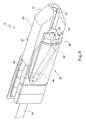
- a catheter actuator is illustrated and is designated generally by the reference numeral 10.
- the actuator 10 includes a first carrier 12 and a second carrier 14 displaceably arranged relative to each other.
- a first catheter sheath component in the form of an electrode sheath 16 of a catheter sheath assembly 17 (Figs. 8 and 9) is securable to a distal end of the first carrier 12 and a second catheter sheath component, in the form of a sleeve 18 (Figs. 8 and 9) of the catheter sheath assembly 17 is securable to a distal end of the second carrier 14.
- the catheter sheath assembly 17 has a distal end 20 which is displaceable between a non-deployed configuration as shown in Fig. 8 of the drawings and a deployed configuration as shown in Fig. 9 of the drawings.
- the movement of the distal end 20 of the catheter sheath assembly 17 between its deployed and non-deployed configurations is controlled by relative movement of the carriers 12 and 14, as will be described in greater detail below.
- the actuator 10 includes a control mechanism 22 (Figs. 3 & 4) carried, in use, by a catheter handle 24 (Fig. 7).
- the control mechanism 22 effects relative displacement between the carriers 12 and 14 to cause displacement of the distal end 20 of the catheter sheath assembly 17 between the non-deployed configuration and the deployed configuration.
- Both the first carrier 12 and the second carrier 14 are, in turn, arranged in the catheter handle 24 so as to be displaceable relative to a further component, being a steering shaft 26 (Figs. 8 and 9) of a catheter assembly.
- the carrier 12 is in the form of a body 28 defining a bore 30.
- a proximal end 32 of the body 28 is shaped to accommodate a boss 34, the body 28 being fast with the boss 34.
- the boss 34 is used to support a part of the electrode sheath 16 functioning as a cable for connection to a source of RF energy. This part of the electrode sheath 16 is omitted from the drawings for the sake of clarity.
- the boss 34 also supports an irrigation conduit (not shown) of the catheter assembly, where applicable.
- the electrode sheath 16 is secured to the boss 34.
- the sleeve 18 is secured to a distal end of the second carrier 14. It will be appreciated that the electrode sheath 16 passes through the second carrier 14 to be secured to the boss 34.
- the actuator 10 includes a control mechanism 22 (Figs. 3 and 4).
- the control mechanism 22 comprises an actuator arm 36 pivotally mounted on the body 28 of the first carrier 12.
- the actuator arm 36 is pivotally mounted to the body 28 via a pivot pin 38 (Figs. 3 and 4) to define a pivot axis about which the actuator arm 36 pivots, in use.
- An arcuate slot 40 is defined in a distal portion of the actuator arm 36, distally of the pivot pin 38.
- a follower 42 which is fast with, and projects radially outwardly from, the tubular member of the second carrier 14, is received in the arcuate slot 40.
- a second follower 44 is arranged on the actuator arm 36 proximally of the pivot pin 38.
- the control mechanism 22 includes a movement control member in the form of a plate 46 (Figs. 3 and 4) which, in use, is fast with a distal part of the handle body 24.
- the plate 46 defines a shaped slot 48. More particularly, the slot 48 is cranked and the follower 44 is received in the slot 48.
- the shape of the slot 48 dictates the manner in which the catheter sheath assembly 17 moves from its non-deployed configuration to its deployed configuration and vice versa.
- the movement control member could adopt other configurations which control the deployment of the distal end 20 of the catheter sheath assembly 17.
- the movement control member could be a fixed cam having a predefined cam surface with at least the follower 44 of the actuator arm 36 being biased to follow the cam surface of the cam.
- the arrangement is such that, when the first carrier 12 is displaced in a direction of arrow 50 (Fig. 1), the first carrier 12 moves by a predetermined amount relative to the second carrier 14.
- the amount by which the first carrier 12 moves relative to the second carrier 14 is shown by the relative positions of the carriers 12 and 14 in Figs. 1 and 2 of the drawings and, similarly, in Figs. 3 and 4 of the drawings.
- the first carrier 12 and the second carrier 14 both move in the direction of the arrow 50 relative to the steering shaft 26 (Figs. 8 and 9).
- an electrode 52 is carried on a distal end of the steering shaft 26.
- Substantially planar electrodes 54 are carried on operatively inner surfaces of petal portions 56 at a distal end of the electrode sheath 16 of the catheter sheath assembly 17.
- the sleeve 18 of the catheter sheath assembly 17 has similar leaves 58 arranged in register with the petals 56 of the electrode sheath 16. Relative movement between the electrode sheath 16 and the sleeve 18 causes the petals 56 of the electrode sheath 16 and the leaves 58 of the sleeve 18 to move from the position shown in Fig. 8 of the drawings to the position shown in Fig. 9 of the drawings. More particularly, this occurs when the sleeve 18 is displaced proximally relative to the electrode sheath 16.
- each petal 56 is approximately 15 mm in length.
- approximately 11 mm of movement is required between the steering shaft 26 and the catheter sheath assembly 17. This is effected by moving the combination of the first carrier 12 and the second carrier 14 in the direction of the arrow 50 relative to the steering shaft 26.
- the catheter handle 24 includes a handle body 60 (Fig. 7).
- a control knob 62 is mounted at a proximal end of the handle body.
- the control knob 62 mounts a first tubular member 64 (Figs. 8 and 9) of the steering shaft 26.
- a second tubular member 66 of the steering shaft 26 is co-axially arranged about the first tubular member 64 and is fast with a steering control mechanism 68 carried at a distal end of the handle body 24.
- a catheter sheath projection arrangement 70 is carried, in turn, on a distal part of the steering control mechanism 68.
- a distal part of the steering control mechanism 68 defines a tubular, axially extending part 72 on which the catheter sheath projection arrangement 70 is carried.
- the body 28 of the first carrier 12 is fast with the catheter sheath arrangement 70.
- the handle body 24 carries a guide tube arrangement 74 for guiding the steering shaft 26 through the handle body 24.
- the catheter sheath projection arrangement 70 is moved from the position shown in Fig. 5 of the drawings to the position shown in Fig. 6 of the drawings.
- the control mechanism 22 of the actuator 10 causes relative displacement between the carriers 12 and 14 to a lesser extent than the displacement of the catheter sheath projection arrangement 70 relative to the steering control mechanism 68.
- the catheter sheath projection arrangement 70 may move approximately 15 mm relative to the steering control mechanism 68 and, consequently, the first carrier 12 moves by the same amount relative to the steering shaft 26, the carrier 14 moves proximally relative to the carrier 12 by a substantially smaller amount, i.e. by about 3 to 4 mm to cause the distal end 20 of the catheter sheath assembly 17 to move from its non-deployed position shown in Fig. 8 of the drawings to its deployed position shown in Fig. 9 of the drawings.
- a catheter actuator is provided which facilitates deployment of a distal end of the catheter sheath assembly in a simple manner using movements with which a clinician would be familiar.
- the movement of the catheter sheath projection arrangement 70 is an operation with which the clinician would be familiar arising from using a catheter handle as described in the applicant's co-pending International Patent Application No. PCT/ AU2006/000266 dated 1 March 2006, entitled "A catheter handle and a catheter assembly including such a handle”.
- a catheter handle of the type described in that patent application provides a benefit in that the clinician has the option of displacing the distal end of an electrode sheath relative to the steering shaft in circumstances where such an action is desirable, eg to obtain access to a difficult to reach site in the patient's body.
- the clinician is able to deploy the petals 56 of the catheter sheath 16.
- it is a movement which would come naturally to the clinician and facilitates ease of use of the catheter assembly.
- a catheter actuator is provided which enables the catheter sheath assembly to be manipulated between its deployed and non-deployed positions in a one-handed operation.
- the arrangement of the actuator 10 is such that the size of the handle 24 is not increased to any significant extent.
Landscapes
- Health & Medical Sciences (AREA)
- Life Sciences & Earth Sciences (AREA)
- Biophysics (AREA)
- Pulmonology (AREA)
- Engineering & Computer Science (AREA)
- Anesthesiology (AREA)
- Biomedical Technology (AREA)
- Heart & Thoracic Surgery (AREA)
- Hematology (AREA)
- Animal Behavior & Ethology (AREA)
- General Health & Medical Sciences (AREA)
- Public Health (AREA)
- Veterinary Medicine (AREA)
- Surgical Instruments (AREA)
- Media Introduction/Drainage Providing Device (AREA)
- Infusion, Injection, And Reservoir Apparatuses (AREA)
Applications Claiming Priority (1)
| Application Number | Priority Date | Filing Date | Title |
|---|---|---|---|
| US84656106P | 2006-09-21 | 2006-09-21 |
Publications (2)
| Publication Number | Publication Date |
|---|---|
| EP1902746A1 true EP1902746A1 (de) | 2008-03-26 |
| EP1902746B1 EP1902746B1 (de) | 2009-06-24 |
Family
ID=38920011
Family Applications (1)
| Application Number | Title | Priority Date | Filing Date |
|---|---|---|---|
| EP07253686A Not-in-force EP1902746B1 (de) | 2006-09-21 | 2007-09-18 | Katheter-Aktuator |
Country Status (9)
| Country | Link |
|---|---|
| US (1) | US20080243115A1 (de) |
| EP (1) | EP1902746B1 (de) |
| JP (1) | JP2008073532A (de) |
| CN (1) | CN101224135A (de) |
| AT (1) | ATE434462T1 (de) |
| AU (1) | AU2007216661A1 (de) |
| CA (1) | CA2601930A1 (de) |
| DE (1) | DE602007001372D1 (de) |
| NZ (1) | NZ561248A (de) |
Families Citing this family (3)
| Publication number | Priority date | Publication date | Assignee | Title |
|---|---|---|---|---|
| US9375550B2 (en) | 2013-03-15 | 2016-06-28 | St. Jude Medical, Atrial Fibrillation Division, Inc. | Catheter actuators providing mechanical advantage |
| US10492857B2 (en) | 2015-08-06 | 2019-12-03 | Boston Scientific Scimed Inc | Deployment control apparatus for a catheter with a deployable array |
| US9931487B2 (en) | 2015-08-06 | 2018-04-03 | Boston Scientific Scimed, Inc. | Bidirectional steering control apparatus for a catheter |
Citations (4)
| Publication number | Priority date | Publication date | Assignee | Title |
|---|---|---|---|---|
| WO1997042867A2 (en) * | 1996-05-13 | 1997-11-20 | Boston Scientific Corporation | Needle grasping apparatus for performing a second therapeutic modality |
| EP1302178A2 (de) | 2001-10-12 | 2003-04-16 | Cordis Corporation | Handgriffentfaltungsmechanismus für medizinische Vorrichtung und Verfahren |
| US20030109778A1 (en) * | 1997-06-20 | 2003-06-12 | Cardiac Assist Devices, Inc. | Electrophysiology/ablation catheter and remote actuator therefor |
| US20040116864A1 (en) * | 2002-12-12 | 2004-06-17 | Boudreaux Chad P. | Catheter introducer assembly having safety shielded needle before and after use |
Family Cites Families (10)
| Publication number | Priority date | Publication date | Assignee | Title |
|---|---|---|---|---|
| US3452740A (en) * | 1966-05-31 | 1969-07-01 | Us Catheter & Instr Corp | Spring guide manipulator |
| US5549542A (en) * | 1992-11-17 | 1996-08-27 | Life Medical Technologies, Inc. | Deflectable endoscope |
| US5352237A (en) * | 1993-02-08 | 1994-10-04 | United States Surgical Corporation | Endoscopic instrument including a handle having a flywheel mechanism |
| DE69433213T2 (de) * | 1993-11-10 | 2004-05-06 | Medtronic, Inc., Minneapolis | Katheter mit Elektrodenanordnung |
| US7967829B2 (en) * | 2003-10-09 | 2011-06-28 | Boston Scientific Scimed, Inc. | Medical device delivery system |
| US8142427B2 (en) * | 2004-04-23 | 2012-03-27 | Boston Scientific Scimed, Inc. | Invasive ablation probe with non-coring distal tip |
| US7591799B2 (en) * | 2004-06-14 | 2009-09-22 | Biosense Webster, Inc. | Steering mechanism for bi-directional catheter |
| US7429261B2 (en) * | 2004-11-24 | 2008-09-30 | Ablation Frontiers, Inc. | Atrial ablation catheter and method of use |
| US7955314B2 (en) * | 2005-05-12 | 2011-06-07 | Greatbatch Ltd. | Articulating handle for a deflectable catheter and method therefor |
| US7465288B2 (en) * | 2005-06-28 | 2008-12-16 | St. Jude Medical, Atrial Fibrillation Division, Inc. | Actuation handle for a catheter |
-
2007
- 2007-09-05 AU AU2007216661A patent/AU2007216661A1/en not_active Abandoned
- 2007-09-06 NZ NZ561248A patent/NZ561248A/en unknown
- 2007-09-14 CA CA002601930A patent/CA2601930A1/en not_active Abandoned
- 2007-09-18 AT AT07253686T patent/ATE434462T1/de not_active IP Right Cessation
- 2007-09-18 EP EP07253686A patent/EP1902746B1/de not_active Not-in-force
- 2007-09-18 DE DE602007001372T patent/DE602007001372D1/de active Active
- 2007-09-20 US US11/903,412 patent/US20080243115A1/en not_active Abandoned
- 2007-09-21 JP JP2007246010A patent/JP2008073532A/ja active Pending
- 2007-09-21 CN CNA2007101527835A patent/CN101224135A/zh active Pending
Patent Citations (4)
| Publication number | Priority date | Publication date | Assignee | Title |
|---|---|---|---|---|
| WO1997042867A2 (en) * | 1996-05-13 | 1997-11-20 | Boston Scientific Corporation | Needle grasping apparatus for performing a second therapeutic modality |
| US20030109778A1 (en) * | 1997-06-20 | 2003-06-12 | Cardiac Assist Devices, Inc. | Electrophysiology/ablation catheter and remote actuator therefor |
| EP1302178A2 (de) | 2001-10-12 | 2003-04-16 | Cordis Corporation | Handgriffentfaltungsmechanismus für medizinische Vorrichtung und Verfahren |
| US20040116864A1 (en) * | 2002-12-12 | 2004-06-17 | Boudreaux Chad P. | Catheter introducer assembly having safety shielded needle before and after use |
Also Published As
| Publication number | Publication date |
|---|---|
| US20080243115A1 (en) | 2008-10-02 |
| AU2007216661A1 (en) | 2008-04-10 |
| CN101224135A (zh) | 2008-07-23 |
| EP1902746B1 (de) | 2009-06-24 |
| CA2601930A1 (en) | 2008-03-21 |
| JP2008073532A (ja) | 2008-04-03 |
| ATE434462T1 (de) | 2009-07-15 |
| DE602007001372D1 (de) | 2009-08-06 |
| NZ561248A (en) | 2009-03-31 |
Similar Documents
| Publication | Publication Date | Title |
|---|---|---|
| EP1853340B1 (de) | Kathetergriff und katheteranordnung mit einem derartigen griff | |
| AU2004212963B2 (en) | Transmitting an actuating force along a curved instrument | |
| EP2760357B1 (de) | Chirurgische Vorrichtungen | |
| EP4074274B1 (de) | Katheteranordnung mit niedrigem profil | |
| EP1902683A1 (de) | Katheteranordnung | |
| US5558673A (en) | Medical probe device and method having a flexible resilient tape stylet | |
| EP2042119A1 (de) | Katheteranordnung | |
| EP2320820B1 (de) | Perkutanes und laparoskopisches operationsinstrument | |
| WO2003057056A1 (en) | Flexible device for ablation of biological tissue | |
| WO2001039681A1 (en) | Medical device having an incrementally displaceable electrode | |
| KR101399555B1 (ko) | 신경차단용 카테터 | |
| EP1902746B1 (de) | Katheter-Aktuator | |
| JP7627988B2 (ja) | 体内の神経を遮断又は調節するための電極装置 | |
| KR20140100451A (ko) | 신경차단용 카테터 | |
| KR101522017B1 (ko) | 신경차단용 카테터 | |
| KR102398566B1 (ko) | 체내의 신경을 차단 또는 조절하기 위한 전극 장치 |
Legal Events
| Date | Code | Title | Description |
|---|---|---|---|
| PUAI | Public reference made under article 153(3) epc to a published international application that has entered the european phase |
Free format text: ORIGINAL CODE: 0009012 |
|
| 17P | Request for examination filed |
Effective date: 20071004 |
|
| AK | Designated contracting states |
Kind code of ref document: A1 Designated state(s): AT BE BG CH CY CZ DE DK EE ES FI FR GB GR HU IE IS IT LI LT LU LV MC MT NL PL PT RO SE SI SK TR |
|
| AX | Request for extension of the european patent |
Extension state: AL BA HR MK YU |
|
| 17Q | First examination report despatched |
Effective date: 20080707 |
|
| AKX | Designation fees paid |
Designated state(s): AT BE BG CH CY CZ DE DK EE ES FI FR GB GR HU IE IS IT LI LT LU LV MC MT NL PL PT RO SE SI SK TR |
|
| GRAP | Despatch of communication of intention to grant a patent |
Free format text: ORIGINAL CODE: EPIDOSNIGR1 |
|
| GRAS | Grant fee paid |
Free format text: ORIGINAL CODE: EPIDOSNIGR3 |
|
| GRAA | (expected) grant |
Free format text: ORIGINAL CODE: 0009210 |
|
| RAP1 | Party data changed (applicant data changed or rights of an application transferred) |
Owner name: CATHRX LTD |
|
| AK | Designated contracting states |
Kind code of ref document: B1 Designated state(s): AT BE BG CH CY CZ DE DK EE ES FI FR GB GR HU IE IS IT LI LT LU LV MC MT NL PL PT RO SE SI SK TR |
|
| REG | Reference to a national code |
Ref country code: GB Ref legal event code: FG4D |
|
| REG | Reference to a national code |
Ref country code: CH Ref legal event code: EP |
|
| REG | Reference to a national code |
Ref country code: IE Ref legal event code: FG4D |
|
| REF | Corresponds to: |
Ref document number: 602007001372 Country of ref document: DE Date of ref document: 20090806 Kind code of ref document: P |
|
| PG25 | Lapsed in a contracting state [announced via postgrant information from national office to epo] |
Ref country code: AT Free format text: LAPSE BECAUSE OF FAILURE TO SUBMIT A TRANSLATION OF THE DESCRIPTION OR TO PAY THE FEE WITHIN THE PRESCRIBED TIME-LIMIT Effective date: 20090624 Ref country code: FI Free format text: LAPSE BECAUSE OF FAILURE TO SUBMIT A TRANSLATION OF THE DESCRIPTION OR TO PAY THE FEE WITHIN THE PRESCRIBED TIME-LIMIT Effective date: 20090624 Ref country code: LT Free format text: LAPSE BECAUSE OF FAILURE TO SUBMIT A TRANSLATION OF THE DESCRIPTION OR TO PAY THE FEE WITHIN THE PRESCRIBED TIME-LIMIT Effective date: 20090624 |
|
| PGFP | Annual fee paid to national office [announced via postgrant information from national office to epo] |
Ref country code: MC Payment date: 20090929 Year of fee payment: 3 |
|
| PG25 | Lapsed in a contracting state [announced via postgrant information from national office to epo] |
Ref country code: PL Free format text: LAPSE BECAUSE OF FAILURE TO SUBMIT A TRANSLATION OF THE DESCRIPTION OR TO PAY THE FEE WITHIN THE PRESCRIBED TIME-LIMIT Effective date: 20090624 Ref country code: LV Free format text: LAPSE BECAUSE OF FAILURE TO SUBMIT A TRANSLATION OF THE DESCRIPTION OR TO PAY THE FEE WITHIN THE PRESCRIBED TIME-LIMIT Effective date: 20090624 Ref country code: SE Free format text: LAPSE BECAUSE OF FAILURE TO SUBMIT A TRANSLATION OF THE DESCRIPTION OR TO PAY THE FEE WITHIN THE PRESCRIBED TIME-LIMIT Effective date: 20090924 Ref country code: SI Free format text: LAPSE BECAUSE OF FAILURE TO SUBMIT A TRANSLATION OF THE DESCRIPTION OR TO PAY THE FEE WITHIN THE PRESCRIBED TIME-LIMIT Effective date: 20090624 |
|
| PGFP | Annual fee paid to national office [announced via postgrant information from national office to epo] |
Ref country code: LU Payment date: 20090930 Year of fee payment: 3 |
|
| NLV1 | Nl: lapsed or annulled due to failure to fulfill the requirements of art. 29p and 29m of the patents act | ||
| PG25 | Lapsed in a contracting state [announced via postgrant information from national office to epo] |
Ref country code: CZ Free format text: LAPSE BECAUSE OF FAILURE TO SUBMIT A TRANSLATION OF THE DESCRIPTION OR TO PAY THE FEE WITHIN THE PRESCRIBED TIME-LIMIT Effective date: 20090624 Ref country code: EE Free format text: LAPSE BECAUSE OF FAILURE TO SUBMIT A TRANSLATION OF THE DESCRIPTION OR TO PAY THE FEE WITHIN THE PRESCRIBED TIME-LIMIT Effective date: 20090624 Ref country code: RO Free format text: LAPSE BECAUSE OF FAILURE TO SUBMIT A TRANSLATION OF THE DESCRIPTION OR TO PAY THE FEE WITHIN THE PRESCRIBED TIME-LIMIT Effective date: 20090918 Ref country code: ES Free format text: LAPSE BECAUSE OF FAILURE TO SUBMIT A TRANSLATION OF THE DESCRIPTION OR TO PAY THE FEE WITHIN THE PRESCRIBED TIME-LIMIT Effective date: 20091005 Ref country code: IS Free format text: LAPSE BECAUSE OF FAILURE TO SUBMIT A TRANSLATION OF THE DESCRIPTION OR TO PAY THE FEE WITHIN THE PRESCRIBED TIME-LIMIT Effective date: 20091024 |
|
| PGFP | Annual fee paid to national office [announced via postgrant information from national office to epo] |
Ref country code: DE Payment date: 20090930 Year of fee payment: 3 |
|
| PG25 | Lapsed in a contracting state [announced via postgrant information from national office to epo] |
Ref country code: NL Free format text: LAPSE BECAUSE OF FAILURE TO SUBMIT A TRANSLATION OF THE DESCRIPTION OR TO PAY THE FEE WITHIN THE PRESCRIBED TIME-LIMIT Effective date: 20090624 Ref country code: BE Free format text: LAPSE BECAUSE OF FAILURE TO SUBMIT A TRANSLATION OF THE DESCRIPTION OR TO PAY THE FEE WITHIN THE PRESCRIBED TIME-LIMIT Effective date: 20090624 Ref country code: SK Free format text: LAPSE BECAUSE OF FAILURE TO SUBMIT A TRANSLATION OF THE DESCRIPTION OR TO PAY THE FEE WITHIN THE PRESCRIBED TIME-LIMIT Effective date: 20090624 |
|
| PG25 | Lapsed in a contracting state [announced via postgrant information from national office to epo] |
Ref country code: BG Free format text: LAPSE BECAUSE OF FAILURE TO SUBMIT A TRANSLATION OF THE DESCRIPTION OR TO PAY THE FEE WITHIN THE PRESCRIBED TIME-LIMIT Effective date: 20090924 Ref country code: PT Free format text: LAPSE BECAUSE OF FAILURE TO SUBMIT A TRANSLATION OF THE DESCRIPTION OR TO PAY THE FEE WITHIN THE PRESCRIBED TIME-LIMIT Effective date: 20091024 |
|
| PG25 | Lapsed in a contracting state [announced via postgrant information from national office to epo] |
Ref country code: DK Free format text: LAPSE BECAUSE OF FAILURE TO SUBMIT A TRANSLATION OF THE DESCRIPTION OR TO PAY THE FEE WITHIN THE PRESCRIBED TIME-LIMIT Effective date: 20090624 |
|
| PGFP | Annual fee paid to national office [announced via postgrant information from national office to epo] |
Ref country code: FR Payment date: 20091016 Year of fee payment: 4 |
|
| PLBE | No opposition filed within time limit |
Free format text: ORIGINAL CODE: 0009261 |
|
| STAA | Information on the status of an ep patent application or granted ep patent |
Free format text: STATUS: NO OPPOSITION FILED WITHIN TIME LIMIT |
|
| 26N | No opposition filed |
Effective date: 20100325 |
|
| PG25 | Lapsed in a contracting state [announced via postgrant information from national office to epo] |
Ref country code: IE Free format text: LAPSE BECAUSE OF NON-PAYMENT OF DUE FEES Effective date: 20090918 |
|
| PG25 | Lapsed in a contracting state [announced via postgrant information from national office to epo] |
Ref country code: GR Free format text: LAPSE BECAUSE OF FAILURE TO SUBMIT A TRANSLATION OF THE DESCRIPTION OR TO PAY THE FEE WITHIN THE PRESCRIBED TIME-LIMIT Effective date: 20090925 |
|
| PG25 | Lapsed in a contracting state [announced via postgrant information from national office to epo] |
Ref country code: MT Free format text: LAPSE BECAUSE OF FAILURE TO SUBMIT A TRANSLATION OF THE DESCRIPTION OR TO PAY THE FEE WITHIN THE PRESCRIBED TIME-LIMIT Effective date: 20090624 Ref country code: MC Free format text: LAPSE BECAUSE OF NON-PAYMENT OF DUE FEES Effective date: 20100930 |
|
| PG25 | Lapsed in a contracting state [announced via postgrant information from national office to epo] |
Ref country code: HU Free format text: LAPSE BECAUSE OF FAILURE TO SUBMIT A TRANSLATION OF THE DESCRIPTION OR TO PAY THE FEE WITHIN THE PRESCRIBED TIME-LIMIT Effective date: 20091225 |
|
| REG | Reference to a national code |
Ref country code: DE Ref legal event code: R119 Ref document number: 602007001372 Country of ref document: DE Effective date: 20110401 |
|
| PG25 | Lapsed in a contracting state [announced via postgrant information from national office to epo] |
Ref country code: DE Free format text: LAPSE BECAUSE OF NON-PAYMENT OF DUE FEES Effective date: 20110401 |
|
| PG25 | Lapsed in a contracting state [announced via postgrant information from national office to epo] |
Ref country code: TR Free format text: LAPSE BECAUSE OF FAILURE TO SUBMIT A TRANSLATION OF THE DESCRIPTION OR TO PAY THE FEE WITHIN THE PRESCRIBED TIME-LIMIT Effective date: 20090624 |
|
| PG25 | Lapsed in a contracting state [announced via postgrant information from national office to epo] |
Ref country code: CY Free format text: LAPSE BECAUSE OF FAILURE TO SUBMIT A TRANSLATION OF THE DESCRIPTION OR TO PAY THE FEE WITHIN THE PRESCRIBED TIME-LIMIT Effective date: 20090624 |
|
| PGFP | Annual fee paid to national office [announced via postgrant information from national office to epo] |
Ref country code: IT Payment date: 20100930 Year of fee payment: 4 |
|
| REG | Reference to a national code |
Ref country code: CH Ref legal event code: PL |
|
| GBPC | Gb: european patent ceased through non-payment of renewal fee |
Effective date: 20110918 |
|
| PG25 | Lapsed in a contracting state [announced via postgrant information from national office to epo] |
Ref country code: IT Free format text: LAPSE BECAUSE OF NON-PAYMENT OF DUE FEES Effective date: 20110918 |
|
| REG | Reference to a national code |
Ref country code: FR Ref legal event code: ST Effective date: 20120531 |
|
| PG25 | Lapsed in a contracting state [announced via postgrant information from national office to epo] |
Ref country code: CH Free format text: LAPSE BECAUSE OF NON-PAYMENT OF DUE FEES Effective date: 20110930 Ref country code: LI Free format text: LAPSE BECAUSE OF NON-PAYMENT OF DUE FEES Effective date: 20110930 |
|
| PG25 | Lapsed in a contracting state [announced via postgrant information from national office to epo] |
Ref country code: FR Free format text: LAPSE BECAUSE OF NON-PAYMENT OF DUE FEES Effective date: 20110930 Ref country code: GB Free format text: LAPSE BECAUSE OF NON-PAYMENT OF DUE FEES Effective date: 20110918 |
|
| PG25 | Lapsed in a contracting state [announced via postgrant information from national office to epo] |
Ref country code: LU Free format text: LAPSE BECAUSE OF NON-PAYMENT OF DUE FEES Effective date: 20100918 |